plush toy model and corresponding 2D cloth pattern. ..... developed a system for
the design of knitted toys [11]. ... knitting pattern for a desired 3D shape.
Designing Plush Toys with a Computer Yuki Igarashi The University of Tokyo
Abstract We introduce Plushie, an interactive system that allows nonprofessional users to design their own original plush toys. To design a plush toy, one needs to construct an appropriate twodimensional (2D) pattern. However, it is difficult for nonprofessional users to appropriately design a 2D pattern. Some recent systems automatically generate a 2D pattern for a given three-dimensional (3D) model, but constructing a 3D model is itself a challenge. Furthermore, an arbitrary 3D model cannot necessarily be realized as a real plush toy, and the final sewn result can be very different from the original 3D model. We avoid this mismatch by constructing appropriate 2D patterns and applying simple physical simulation to it on the fly during 3D modeling. In this way, the model on the screen is always a good approximation of the final sewn result, which makes the design process much more efficient. We use a sketching interface for 3D modeling and also provide various editing operations tailored for plush toy design. Internally, the system constructs a 2D cloth pattern in such a way that the simulation result matches the user’s input stroke. We successfully demonstrated that non-professional users could design plush toys or balloon easily using Plushie.
1. Introduction A computer can be a powerful tool for designing real-world artifacts. One can build a virtual three-dimensional (3D) model in a computer (Computer-aided Design, CAD) and use it to run various simulations (Computer-aided Engineering, CAE), without the need to build and damage costly real objects. The benefits are evident in many areas, from architecture to automobile design. However, these tools are mainly designed for professional users and not quite accessible for everybody. Construction of a 3D model using a standard CAD system is tedious and running a physical simulation using a standard CAE system requires expert knowledge. Our goal is to bringing the benefit of computer-aided design and engineering to the hands of nonprofessional users, including children. This article introduces our plush-toy design system [15], Plushie, as an example of our efforts to achieve the goal. Plush toys are one of the most familiar objects in our daily life but their design is difficult. One must design an appropriate twodimensional (2D) pattern to obtain a particular 3D shape, but the relationship between the two is nontrivial, and intensive experience and knowledge is required to do so appropriately. As a result, most people simply buy ready-made toys and do not enjoy the design and construction of their own plush toys. We have tried to enable these people to design their own toys by providing an easy but powerful modeling tool that combines a sketching interface and tight integration of physical simulation into the modeling process. Our system, Plushie, allows the user to design a plush toy from scratch by simple sketching operations [15]. The user first draws a desired silhouette and the system automatically generates a 3D plush toy model and corresponding 2D cloth pattern. The user can also edit the model, such as by cutting the model and adding a part,
Takeo Igarashi The University of Tokyo / JST, ERATO
using simple sketching interface and the 3D model and 2D cloth pattern are automatically updated. The 3D model is the result of a physical simulation that mimics the inflation of the sewn 2D cloth patched. Therefore, the model on the screen is always a good estimation of the final sewn result (Figure 1). We run a workshop in a museum to have novice users try our system and have observed that even children can design their own plush toys.
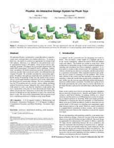
Figure 1: Overview We first give an overview of sketching interfaces for 3D modeling and previous efforts on enabling end users to design physical objects. We then describe the user interface and implementation of the Plushie system, followed by results and user experiences. Finally, we conclude the article with some discussion on the future work.
2. Sketching Interfaces for 3D Modeling The sketching interface part of Plushie is an evolution of the system we presented in 1999, Teddy [9]. It allows the user to create an interesting 3D model simply by sketching the desired silhouette of the target model (Figure 2 left). It was designed for the modeling of freeform, rotund models, which was particularly difficult using standard modeling interfaces. Figure 3 shows an example modeling sequence in Teddy. The user's strokes are shown in red, and everything else is inferred and drawn by the system. The user first draws the silhouette of the base primitive and the system generates the corresponding 3D geometry. The user then draws a stroke across the model and the system cuts the model at the line. The user can also add parts to the base model by drawing two strokes. Figure 2 right shows several 3D models created using the system.
Figure 2. Screenshot of Teddy and sample 3D models created using the system.
[12]. One problem of an automatic approach that relies on purely geometric criteria is that it is difficult to perceptually capture important features such as symmetry. Mori and Igarashi’s system [16] helps manual segmentation of a model by providing automatic flattening and showing the result of physical simulation. These systems make plush toy design more accessible, but the fundamental challenge of creating an original plush toy is still unresolved. Figure 3. Modeling session in Teddy. The user can create a 3D model using simple sketching operations. Several sketching systems for freeform shapes have been developed after the presentation of Teddy. The original Teddy system used polygonal meshes but some later systems experimented with other representations such as voxels [17] and implicit surfaces [20]. Some systems extended the interface to support subsequent editing by direct manipulation. ShapeShop [21] represents a model as a collection of blob primitives and allows the user to move or scale each primitive. Fibermesh [22] keeps the original stroke as a control curve on the model surface and allow the user to adjust the shape by deforming the curves. However, all these systems are designed for purely virtual 3D models and there was no consideration to physical properties of materials. Plushie is innovative in that it shows the possibility of applying sketching interface for freeform shapes to the design of physical objects.
4. The Plushie System The system consists of two windows: one shows the 3D plush toy model being constructed and the other shows the corresponding 2D pattern (Figure 4). The user works on the 3D view, interactively building the 3D model by using a sketching interface. The 2D view is mainly for reference but the user can also edit the 2D pattern directly when desired. The 3D model is produced from a physical simulation of the assembled 2D pattern. After each input from the user, the system updates the 2D pattern so that the simulation result matches the user input. This guarantees that the model is always realizable as a real plush toy and that the 2D pattern is readily usable as a template for cutting and sewing real fabric.
3. Designing Physical Models with a Computer Another key aspect of our work is the tight integration of physical simulation into the 3D modeling process. In traditional applications, modeling and simulation have been completely separated. A virtual model is created in 3D modeling software without considering any physical constraints, and then passed later to a simulation environment. If the simulation result reveals a problem, the user returns to modeling to fix the problem. We try to make it more efficient by running the simulation concurrently with modeling, so that only models that are physically realizable are created. In this way, the user can more efficiently explore the design dimensions within realistic constraints. From the user’s point of view, the model generated by the system may not exactly take his/her input shape but takes a physically realizable shape reflecting the input shape. Some recent systems have tried to incorporate fast physical simulation into an interactive design process. Igarashi and Hughes developed a mark-based interface for putting clothing on a virtual character [8], and Decaudin et al. proposed a system for designing an original garment via sketching [4]. Both used simple geometric simulations to represent the physical properties of cloth material. Masry and Lipson described a system in which the user can quickly build a CAD model via sketching and immediately apply finite element analysis to the model [13]. However, model construction is computed before simulation in these systems, and no dynamic feedback loop exists between the simulation result and the original user input. There are also a couple of efforts to support the design of physical objects by end users in computer graphics research community. Mitani and Suzuki [14] and Shatz et al. [18] presented automatic segmentation of a 3D model into developable patches for constructing paper craft models. Similarly, Julius et al. proposed automatic segmentation and flattening of a model for plush toys
Figure 4: A screen snapshot of the Plushie system.
The modeling operations are based on the Teddy system [9]. The user interactively draws free-form strokes on the canvas as gestures and the system automatically generates a 3D model and corresponding 2D cloth pattern. We also provide some special editing operations tailored for plush toy design. Creating a New Model: Starting with a blank canvas, the user creates a new plush toy model by drawing its silhouette as a closed free-form stroke. The system automatically generates two cloth patches corresponding to the stroke and visualizes the shape of the resulting plush toy by applying a simple physical simulation (Figure 5).
Figure 5: Creating a new model.
Cut: The user can cut the model by drawing a stroke that starts outside of the model, crosses it, and ends outside of the model (Figure 6). The model is cut at the intersection and flat patch is generated at the cross-section. This operation is useful for creating relatively flat surfaces, such as those in a foot or belly.
models because one needs to divide a rounded surface into many almost-developable small patches (Figure 19 bottom).
Figure 6: Cut operation.
Creation of a Part: The user can add protruding parts such as the ears and arms to the base model by drawing a single stroke that defines the silhouette of the part. The stroke should start and end on the base model (Figure 7 a). The system generates two candidate shapes and presents them to the user as suggestions [7] (Figure 7 b). One is for fat, rounded parts like the body, arm, and leg (Figure 7 c). Their base is connected to the base model with an open hole. The other candidate shape is for thin parts like ears and the tail, whose base is closed (Figure 7 d). The user clicks the desired thumbnail and the system updates the main model accordingly. We found that the ability to create thin parts with a single stroke is particularly useful. They are frequently seen in real toys and are difficult to design using standard modeling software. Figure 20 shows a couple of example models with thin parts.
The user can add a new seam in the seam line drawing mode by drawing a free-form stroke on the model surface (Figure 9). The corresponding cloth patch is then automatically cut along the new seam line. If the stroke crosses the entire patch, the patch is divided into two separate patches. If the stroke starts or ends in the middle of a patch, it becomes a dart. The 3D geometry does not change immediately after the insertion of these seam lines, but the user can pull the seam line afterwards to modify the shape. This operation is very useful for creating a salient feature in the middle of a flat patch. Deletion is achieved by tracing the target seam line in the erasing mode. This merges the separated patches together and thus flattens the area (Figure 10).
(a) (b) (c) (d) Figure 9: Insertion of a seam line. (a) Before drawing a line. (b) After drawing a line. (c) The seam line’s two endpoints snap at other seam lines. (d) After pulling the seam line. (c)
(a)
(b) (d)
Figure 7: User interface of part creation. (a) The user draws a stroke and (b) the system suggests two different possibilities. The user chooses one (c, d).
Pull: The user can grab a seam line and pull it to modify the shape. For example, the user can pull an ear to make it larger when it is smaller than the other (Figure 8). The pulling operation begins when the user starts dragging on the background region near a seam line. The system changes the mouse cursor when it approaches a seam line to indicate that the user can start pulling. We use the peeling interface introduced by Igarashi et al. [10] to adjust the size of the region to be deformed; that is, the larger area is deformed as the user pulls more. The system continuously updates the 2D cloth pattern during pulling and shows the simulation result in the 3D view.
Figure 8: User interface of the pull operation.
Insertion and Deletion of Seam Lines: The modeling operations performed thus far automatically generate 2D patches according to predefined algorithms and seam lines (patch boundaries) appear on the 3D model surface without the user's explicit control. However, it is sometimes desirable for knowledgeable users to design seam lines manually, for more detailed control. This is especially important when using non-stretchy cloth as in balloon
Figure 10: Deletion of a seam line.
Operations on the 2D Pattern View: The 2D pattern view is mainly used to preview the pattern to be printed for sewing, but it also works as an interface for advanced users to edit the pattern directly. The preview helps the user to understand the relationship between the 3D model and 2D patches and gives a sense of the labor required for assembling the patches. The system can display how patches are connected by showing connectors or paired numbers (Figure 11). Connectors are useful for understanding the relationship on the screen and numbers are useful as a printed reference on each patch. The system provides an automatic layout and manual arrangement interface for preparing the final pattern to be printed. The system also allows the user to edit the patches directly by using the pulling interface. The user can grab the boundary of a patch and pull it to deform the shape [10]. We again use a peeling interface to adjust the size of area to be deformed. The effect of 2D deformation immediately appears in the 3D view because of the physical simulation. The ability to deform an individual patch is useful for designing asymmetric shapes such as a penguin belly (Figure 12). The pull operation is also useful for opening a dart line to make a flat patch swell more (Figure 13).
of edge length) runs ten times in each cycle to prevent excessive stretch. It takes approximately 30 simulation cycles (2 seconds) to converge in our typical examples. Although it is possible to show the result only after the convergence, we decided to show the intermediate shape because test users preferred to see the inflation process. (a) (b) (c) Figure 11: Patches connected to each other using connectors (b) and numbers (c).
vi vi
lij fj
eij vj
(a) (b) Figure 14: Our simple model to mimic stuffing effect. (a) the system first moves each face to its normal direction slightly to mimic the effect of internal pressure. (b) the system adjusts the length of each edge to preserve the integrity of cloth material.
5.2. 3D Modeling Operations Figure 12: Pulling a 2D patch.
Figure13: Opening a dart line.
5. Implementation This section briefly describes these implementation of Plushie. More detailed description is found in our original paper [15]. We use a standard triangle mesh for the representation of 3D model and the 2D patches. We use relatively coarse mesh (1000-2000 vertices) to achieve interactive performance. Each vertex, edge, and face of the 3D mesh is associated with corresponding entities in the 2D mesh. A 3D mesh is always given as a result of applying a physical simulation to the assembled 2D pattern. To be more precise, the physical simulation applied to the 3D mesh is governed by the rest length of each edge and the rest length is defined in the 2D mesh. For each modeling operation, the system constructs the initial 2D patches and the 3D geometry corresponding to the input stroke, and then runs a physical simulation to update the 3D geometry. The system then adjusts the patch shape so that the simulation results match the input strokes.
5.1. Physical Simulation We use a simple static method for the physical simulation. We examined other, more elaborate methods, such as finite element methods [6], dynamic simulation [3], and energy minimization [2], but we found that the simple approach is best suited for our purpose. It is easy to implement, fast enough for interactive modeling, and sufficiently robust for dealing with adverse user operations. More importantly, it produces a reasonable estimation of the resulting plush toy shape. As shown in Figure 14, it successfully reproduces characteristic behaviors seen in the stuffed cloth. This algorithm is also used in a garment capture system [23]. In each simulation cycle, the system first moves each face slightly in its normal direction to mimic the effect of internal pressure (Figure 14 a). The system then adjusts the length of each edge to preserve the integrity of the cloth material [5] (Figure 14 b). We decided to prevent stretching only and tolerate compression because plush toys' rotund shape is generated from compression (small winkles) along the seam lines. The second part (adjustment
Creating a New Model: The input stroke is projected onto an invisible plane at the center of the world facing the screen, and the system generates an initial two-sided mesh inside of the closed region. Each side of the mesh is used directly as a 2D patch for the model. The system then applies the physical simulation to the mesh. It inflates the mesh to the direction perpendicular to the viewing direction, but its silhouette actually becomes smaller as it inflates (Figure 15). The system waits until the simulation converges and then starts to adjust the 2D pattern so that the simulation result matches the input stroke. Specifically, the system calculates the distance di from a vertex vi of the 3D mesh along the seam line to the corresponding point pi in the projected input stroke along its normal direction, and moves the corresponding 2D vertex ui on the patch boundary to its normal direction by that amount di. After modifying the patch boundary, the system updates the 2D mesh so that vertices are uniformly distributed inside of the patch. The length of the edges in the updated 2D mesh is then used as the new rest length in the simulation. The system repeats this adjustment process and the physical simulation until convergence. It takes approximately 20 iterations (2 seconds) to converge in our typical examples. This simple algorithm works well in practice for our application. Figure 16 shows some examples in which our algorithm successfully found appropriate 2D patches that yielded the desired 3D shapes. In some situations, the input shape is not realizable as a plush toy model consisting of two patches. For example, a sharp concavity is not realizable without causing self-intersection in the 2D patch. In these cases, the system terminates the optimization process, leaving a gap between the input stroke and the 3D model. This indicates that the desired shape is not possible with two patches. The user must add additional seam lines to obtain more control.
pi n vi
ui
di
the simulation is applied separately to the base mesh and the new part. The base mesh inflates independently of the part mesh, and the base curve is treated as a positional constraint in the simulation of the part mesh (we simply do not move these vertices in the simulation cycle).
di
Figure 15: Adjustment process after creation. The system enlarges the 2D pattern so that the simulation result matches the input stroke. The 2D boundary vertex (v) moves in its normal direction by the amount proportional to the distance between the corresponding 3D vertex and the input stroke.
Figure 16: Physical simulation and shape adjustment. The red lines indicate the input strokes. The top row shows the result of converting the input into patterns directly, and the bottom row shows the outcome when the adjustment process is applied to the patterns. The green shapes in the middle show the simulation results and the brown ones on the right show the real fabric models, both resulting from the 2D pattern on the left.
Cut: The system constructs a curved surface by sweeping the cutting stroke on the screen to the viewing direction and dividing the mesh along the surface. The right-hand side of the surface is removed and a new mesh is created on the cross-section. The cross-section is always developable, so the system simply flattens it and uses it as a 2D patch. The system then applies inflation process to the model. Note that the silhouette of the inflated 3D model does not exactly matches with the input cut stroke because we do not apply any adjustment as in the initial creation. Creation of a Part: The system first projects the two endpoints of the input stroke onto the base model surface. A plane that passes through these 3D points and is facing toward the screen is constructed and the input stroke is projected onto it. The system then draws an ellipse on the model surface for constructing a fat part and draws a line for creating a thin part (Figure 17). The ellipse or the line (what we call base curves) is also projected to the plane. The system generates a 2D mesh on the projection plane in the area enclosed by the projected input stroke and the projected base curve. The 2D mesh is duplicated and serves as 2D pattern and as the initial 3D geometry for the added part. As in the initial model creation case, the flat two-sided 3D mesh is inflated by physical simulation. The silhouette of the added part gradually shrinks and the system enlarges the 2D pattern so that the silhouette matches the input stroke as in initial creation. In case of a part with an elliptic base curve, the system cuts open the base surface and stitches it with the newly created mesh. The result is a single connected mesh, and physical simulation is applied uniformly to the entire mesh. On the other hand, the system does not open the base mesh in case of the linear base curve. The new part is created as an independent closed mesh and
(a) (b) (c) Figure 17: Creation of a part. The system projects the input stroke to a working plane and cuts the base mesh with either an elliptic curve or a line (b). The 3D geometry is constructed by creating a mesh between the projected stroke and the base curves (c).
Pull: The pull operation is a bit involved because the system cannot directly modify the 3D mesh and must do so indirectly by deforming the corresponding 2D pattern. As the user starts pulling a vertex on a seam line, the system first constructs a projection plane that passes through the seam line (Figure 18). The mouse cursor position on the screen is projected onto the projection plane, and it is used as a target position for the pulled vertex during subsequent dragging. The system computes the displacement δi in the local coordinate frame on the projected plane from the original position vi to the target position hi, and moves the corresponding vertices ui0 and ui1 in the 2D mesh in their local coordinate frames by that amount δi. These 3D and 2D coordinate frames are defined by the pulled vertex’s normal vector and the direction of the seam line. The system iterates this displacement process with physical simulation until it converges. To achieve a smooth deformation, the system also moves the surrounding vertices in the 2D mesh using the curve manipulation method introduced in Igarashi et al. [10]. It enlarges the region to be deformed proportional to the displacement of the pulled vertex.
hi vi
u i0
ui1
Figure 18: Pulling a vertex on a seam line.
Insertion and Deletion of Seam Lines: Insertion of a new seam line is straightforward. The system simply cuts the patch along the added seam line, and basically does not change the result of simulation. Deletion is more complicated because the merged patch is not necessarily developable. The system applies an approximate flattening operation [19] to the merged 3D surface to obtain the geometry of the new 2D patch.
6. Results Plushie is implemented as a JavaTM program. Construction of 2D patterns and a physical simulation run in real-time on a 1.1 GHz Pentium M PC. We designed a couple of plush toys using our system and created a real toy based on the printed pattern. A
modeling session typically takes 10-20 minutes and sewing takes 3 -5 hours. Figure 19 shows a plush toy and balloon model designed in our system. It shows that the physical simulation successfully captures the overall shape of the real objects. We interviewed with professional balloon designers and they supported our system, saying that it can significantly reduce the time necessary for designing original balloon.
Figure 21: Example of original plush toys designed and created by children in the workshop.
7. Conclusions
Figure 19: A plush toy and a balloon designed in our system.
The user can assign different textures to individual patches (Figure 20). Therefore the user can explore various design possibilities before actuary sewing the real fabric (such as Figure 20 right). These models also demonstrate the effectiveness of thin parts.
We introduced a plush toy design system as an example of our efforts to make computer-aided design and engineering accessible to end users. The system allows the user to quickly design his or her own plush toy simply by combining simple sketching operations. The user draws the desired silhouette on the canvas and the system automatically generates a 3D plush toy model and a 2D cloth pattern. The system runs a simple physical simulation in the background so that the resulting 3D model is always a good estimation of the final sewn result. The user can construct a real plush toy by printing the pattern and sewing them together. To further demonstrate the effectiveness of the approach, we also developed a system for the design of knitted toys [11]. A knitted toy is a plush toy made of knitted yearns instead of cloth patches. One can construct a knitted toy by knitting yarns according to a specific knitting pattern, but it is difficult to induce appropriate knitting pattern for a desired 3D shape. The system, Knitty, allows the user to design an original knitted toy by simply drawing the desired silhouette (Figure 22). The system then generates a 3D knitted animal model and corresponding knitting diagram. We also ran a workshop using the system and observed that children can design their own knitted animals using the system.
Figure 20: Example of texture changed. These models have many thin parts.
We ran four small workshops to test the usability of the system and found that novice users, mainly children, can successfully create original plush toys using our system. Here is an observation from one of these workshops. Nine children, approximately 10-14 years old, joined the workshop accompanied by their parents. We gave a brief tutorial at the beginning and had them design their own plush toys using the system. It took about an hour for the design. They then printed the designed pattern and sewed a real toy in approximately 3 hours. Figure 21 shows a couple of plush toys created in the workshop. Participants quickly learned how to use the system and successfully designed the 3D models they wanted, with some help from volunteers. Furthermore, they enjoyed the process. These toys were their own creations and oneof-a-kind designs. Participants also gave us valuable feedback for future improvement. They wanted to have some auxiliary functions such as the ability to design symmetric parts and remove existing parts, but no one complained about the quality of the visual simulation. A perfectly accurate simulation is not necessary because many small variations inevitably occur during the real sewing and stuffing process.
Figure 22: Knitty system allows the user to design an original knitted toy by simply drawing the desired silhouette.
Interactive 3D modeling assisted by concurrent physical simulation can be a powerful tool in many other application domains. For example, if one can run an aerodynamic simulation during the interactive design of a paper airplane model, it might be helpful to intelligently adjust the entire geometry in response to the user's simple deformation operations so that it can actually fly. This kind of interaction would make it easier for designers to pursue aesthetic goals while satisfying engineering constraints. Real-time simulation does require high-performance computing resources, but some meaningful support should be possible by carefully limiting the target task and designing appropriate interfaces as shown in this paper. We hope that our work inspires more work in this direction.
References 1.
AGRAWALA, M., DOANTAM, P., HEISER, J., HAYMAKER, J., KLINGNER, J., HANRAHAN, P., AND TVERSKY, B. 2003. Designing effective step-by-step assembly instructions. ACM Transactions on
Graphics (In Proceedings of SIGGRAPH 2003), 22(3), 828–837. 2.
BREEN, D.E., HOUSE, D.H., AND WOZNY, M.J. 1994. Predicting the drape of woven cloth using interacting particles. In Proceedings of SIGGRAPH 1994, 365–372.
3.
CHOI, K.-J., AND KO, H.-S. 2002. Stable but responsive cloth. ACM Transactions on Graphics (In Proceedings of SIGGRAPH 2002), 21(3), 81–97.
4.
DECAUDIN, P., JULIUS, D., WITHER, J., BOISSIEUX, L., SHEFFER, A., AND CANI, M.-P. 2006. Virtual garments: A fully geometric approach for clothing design. Computer Graphics Forum (In Eurographics 2006 Proc.), 25(3), 625–634.
5.
DESBRUN, M., SCHRODER, P., AND BARR, A. 1999. Interactive animation of structured deformable objects. In Proceedings of Graphics Interface 1999, 1–8.
6.
GRINSPUN, E., KRISL, P., AND SCHRODER, P. 2002. CHARMS: A simple framework for adaptive simulation. ACM Transactions on Graphics, 21(3), 281–290.
7.
IGARASHI, T., AND HUGHES, J.F. 2001. A suggestive interface for 3D drawing. 14th Annual Symposium on User Interface Software and Technology (In ACM UIST 2001), 173–181.
8.
IGARASHI, T., AND HUGHES, J.F. 2002. Clothing manipulation. 15th Annual Symposium on User Interface Software and Technology (In ACM UIST 2002), 91–100.
9.
IGARASHI, T., MATSUOKA, S., AND TANAKA, H. 1999. Teddy: A sketching interface for 3D freeform design. ACM SIGGRAPH 1999, 409–416.
10.
IGARASHI, T., MOSCOVICH, T., AND HUGHES, J.F. 2005. As-rigid-aspossible shape manipulation. ACM Transactions on Computer Graphics (In ACM SIGGRAPH 2005), 24(3), 1134–1141.
11.
Yuki Igarashi, Takeo Igarashi, Hiromasa Suzuki. "Knitty: 3D Modeling of Knitted Animals with a Production." Eurographics 2008 Annex to the Conference Proceedings (ISSN 1017-4656), pp.187-190.
12.
JULIUS, D., KRAEVOY, V., AND SHEFFER, A. 2005. D-Charts: quasi developable mesh segmentation, Computer Graphics Forum. In Proceedings of Eurographics 2005, 24(3), 981–990.
13.
MASRY, M., AND LIPSON, H. 2005. A sketch-based interface for iterative design and analysis of 3D objects, In Proceedings of Eurographics Workshop on Sketch-Based Interfaces, 109–118.
14.
MITANI, J., AND SUZUKI, H. 2004. Making papercraft toys from meshes using strip-based approximate unfolding. ACM Transactions on Graphics, 23(3), 259–263.
15.
Mori Y., and Igarashi, T. 2007. Plushie: An interactive design system for plush toys. ACM Transactions on Graphics (Proceedings of SIGGRAPH 2007), vol26, No.3, Article No. 45.
16.
MORI, Y., AND IGARASHI, T. 2006. Pillow: Interactive pattern design for stuffed animals. DVD publication at SIGGRAPH 2006 Sketches & Applications.
17.
Shigeru Owada, Frank Nielsen, Kazuo Nakazawa, and Takeo Igarashi, "A Sketching Interface for Modeling the Internal Structures of 3D Shapes", Smart Graphics 2003, Lecture Notes in Computer Science (LNCS) vol.2733, pp.49-57, Springer-Verlag.
18.
Shatz et al.
19.
SHEFFER, A., LEVY, B., MOGILNITSKY, M., AND BOGOMYAKOV, A. 2005. ABF++: Fast and robust angle based flattening. ACM Transactions on Graphics, 24(2), 311–330.
20.
Alexe, A., Barthe, L., Cani M., Gaildrat, V., 2005. Shape Modeling by Sketching using Convolution Surfaces, In Proceedings of Pacific Graphics 2005.
21.
Ryan Schmidt, Brian Wyvill, Mario Costa Sousa, Joaquim A. Jorge. 2005. ShapeShop: Sketch-Based Solid Modeling with BlobTrees, 2nd Eurographics Workshop on Sketch-Based Interfaces and Modeling, pp. 53-62.
22.
Nealen, A., Igarashi, T., Sorkine, O., and Alexa, M. "FiberMesh: Designing Freeform Surfaces with 3D Curves", ACM Transactions on Computer Graphics, Proceedings of SIGGRAPH 2007, vol.26, No.3, Article No.41, 2007.
23.
Bradley, D., Popa, T., Sheffer, A., Heidrich, W., and Boubekeur, T. Markerless Garment Capture. ACM Transactions on Computer Graphics, Proceedings of SIGGRAPH 2008, Vol.27, No.3, Article No. 99.