610
IEEE JOURNAL OF OCEANIC ENGINEERING, VOL. 27, NO. 3, JULY 2002
Detection of Mines in Acoustic Images Using Higher Order Spectral Features Vinod Chandran, Senior Member, IEEE, Steve Elgar, Member, IEEE, and Anthony Nguyen, Student Member, IEEE
Abstract—A new pattern-recognition algorithm detects approximately 90% of the mines hidden in the Coastal Systems Station Sonar0, 1, and 3 databases of cluttered acoustic images, with about 10% false alarms. Similar to other approaches, the algorithm presented here includes processing the images with an adaptive Wiener filter (the degree of smoothing depends on the signal strength in a local neighborhood) to remove noise without destroying the structural information in the mine shapes, followed by a two-dimensional FIR filter designed to suppress noise and clutter, while enhancing the target signature. A double peak pattern is produced as the FIR filter passes over mine highlight and shadow regions. Although the location, size, and orientation of this pattern within a region of the image can vary, features derived from higher order spectra (HOS) are invariant to translation, rotation, and scaling, while capturing the spatial correlations of mine-like objects. Classification accuracy is improved by combining features based on geometrical properties of the filter output with features based on HOS. The highest accuracy is obtained by fusing classification based on bispectral features with classification based on trispectral features. Index Terms—Higher order spectra, image classification, mine detection, object detection, pattern recognition, sonar target recognition.
I. INTRODUCTION
T
HE DETECTION of mines in sonar imagery is challenging because the images contain spatially varying clutter and noise, and target signatures are not consistent in shape, strength, or size. Although most signatures exhibit separated high- (highlight) and low-valued (shadow) regions, sonar returns from some mines show little highlight and others have weak shadows. Consequently, approaches to mine detection [1]–[3] have compromised on the design of a matched filter, which often is an approximation of a segment of an ideal target 17 signature. The detection density approach [1] uses a 3 linear filter with background, highlight, dead-zone, and shadow regions along the range. The AMDAC algorithm [3] uses a nonlinear filter with negative coefficients in the pre- and post-target zones to prevent the detection of objects with highlights or shadows that are greater than mine size. This filter modifies every pixel of an input image, and the strength of the output is indicative of the match of the region surrounding the pixel to a target signature. Many pixels, some of them belonging to Manuscript received July 20, 2001; revised March 20, 2002. This work was supported in part by the U.S. Office of Naval Research and is Woods Hole Oceanographic Institution Contribution 10482. V. Chandran and A. Nguyen are with the Queensland University of Technology, Brisbane, Qld 4001, Australia. S. Elgar is with the Woods Hole Oceanographic Institution, Woods Hole, MA 02543 USA. Publisher Item Identifier S 0364-9059(02)06308-2.
objects that clutter the image, can exhibit high-valued outputs. A detection threshold eliminates other pixels from further consideration. Mines and clutter are distinguished by extracting spatial correlation and density features from groups of pixels in the detection image and from target-sized windows around the detected regions in the input image [3]. Here, a new algorithm for detecting mines in sonar images is described (Section II). Similar to the detection density adaptive clutter filter [1], [2] and the improved AMDAC [3], the algorithm uses a matched filter designed to capture the highlight, shadow, and background information in a target signature. However, a modified approach is used to extract additional spatial correlation and shape information from the matched filter output. The normalized image is divided into small (but larger than the signature of a mine) blocks for analysis, with each block passed through a matched filter. The demeaned matched filter output is adaptively thresholded by setting to zero the values that lie between a positive and a negative level. The thresholds are lowered in steps of an estimated noise variance until the output contains at least two objects (or connected groups of nonzero valued pixels). The shapes of these objects in the presence of a mine differ from the shapes that arise from clutter and noise. Unlike the detection density approach [1], the matched filter output values above the threshold are not constant. Thus, the output contains strength, as well as shape information. It is important that features used to capture the shape and strength of the objects be invariant to translation, size changes, and some degree of rotation because the mine can occur anywhere with any size within the image section chosen for analysis. Invariant higher order spectral (HOS) [4]–[8] features are designed to meet these requirements and also are robust to additive Gaussian noise. Combining bispectral- and trispectral-based features with those based on geometrical properties of the filter output result in detection of approximately 90% of the mine-like objects in the Naval Surface Warfare Center, Dahlgren Division, Panama City, Florida, Coastal Systems Station (CSS) Sonar0, 1, and 3 high-resolution side-scan sonar imagery databases [1]–[3], with about 10% false alarms (e.g., 10% of the mine-free image sections were incorrectly classified as containing a mine) (Section III). II. THE ALGORITHM The principal stages of the algorithm are as follows. A. Range Normalization The bottom brightness of sonar returns varies owing to: 1) inadequate compensation for reduction in signal strength caused
0364-9059/02$17.00 © 2002 IEEE
CHANDRAN et al.: DETECTION OF MINES IN ACOUSTIC IMAGES
611
output of the matched filter contains a large positive peak. In contrast, in the absence of a mine (i.e., noise only) the output of the matched filter contains low amplitude peaks and valleys. The filter is not zero mean and the mean value is subtracted from the output after filtering. E. Adaptive Thresholding
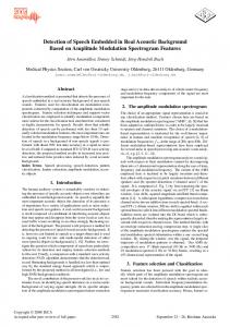
Fig. 1. Impulse response of the matched filter [1].
by spherical spreading of acoustic energy; 2) weak returns from highly absorbent regions such as mud; 3) strong returns from highly reflective bottoms such as gravel [2]. Range normalization, as recommended by the CSS, is applied by dividing raw values by the average over a row (cross-range) at each range. To retain more signal strength information, instead of clipping high values, the resulting image is contrast stretched to have values between 0 and 1. B. Adaptive Wiener Filtering A pixel-wise spatially adaptive Wiener filter [9] is used to reduce the additive noise component (assumed to be white) without destroying image detail. This filter computes the local characteristics (mean and variance) of the image at each pixel over an 8 8 block. The impulse response of the filter is space variant and varies with the local detail. When the local contrast is high, a greater degree of smoothing is acceptable, resulting in an output image with reduced noise, but without as much blurring as from a nonadaptive filter. The wiener2 function in Matlab is used for this step. C. Block-by-Block Processing 64 pixel blocks Each input image is subdivided into 64 (e.g., larger than the target signature). A classification decision (mine present or not) is made for each block. In practice, the image may be divided into overlapping blocks such that every mine will be contained (not split between blocks) in at least one block. For the tests reported here, overlapping blocks were used in the neighborhood of each mine, while the rest of the image was divided into nonoverlapping blocks. D. Matched Filtering Each block from the Wiener filtered image is passed through a matched filter designed considering an ideal target signature consisting of a highlight, a shadow, and a region in between [1]. The impulse response of the 9 9 pixel filter is shown in Fig. 1. A design based on minimization of energy for clutter and maximization of energy for mines is attractive theoretically, but not in practice, because the filter size is a fraction of the target signature, which varies considerably from mine to mine. The main purpose of this filter is to transfer information from spatial correlations (the highlight and shadow regions and their separation) to the values of the pixels in the output. If a mine is present, the
Detection accuracy and false-alarm rates are sensitive to the threshold applied to the match filtered image. The optimal threshold depends on the signal strength (pixel values in the presence of a mine) and the background noise, both of which vary spatially. Rather than consider pixel values above a set threshold as candidates for mine-containing regions to be examined further in groups, two adaptive thresholds on either side of the mean value for a block (set to zero by subtracting the mean) are applied, and pixel values between the two thresholds are forced to zero. Values outside the thresholds are retained (not clipped) and provide both strength and shape information to the feature extraction stage. The initial levels of the threshold depend on the power per pixel in a block with a mine, and are determined from the training set. The magnitude of the negative threshold was set to 80% of the positive threshold to ensure that negative peaks also are exhibited for mine-containing regions. The thresholds are adapted, thereafter, for every block, during training and testing. If the output after thresholding is zero for a given block, the thresholds are lowered in steps of the estimated standard deviation of noise (estimated at the Wiener filter stage) until the output contains two or more objects (nonzero valued pixel clusters). The adaptive thresholding reduces most of the noise-only sections of the image to a random distribution of small pixel clusters, whereas mine-containing sections exhibit prominent positive and negative peaks. The outputs from the sequence of processing stages up through matched filtering for a block containing a mine are shown in Fig. 2. The difference between the thresholded outputs for blocks containing a mine, only noise, and a mine-like impostor (e.g., a false alarm) are shown in Fig. 3. F. Feature Extraction The strengths, sizes, and shapes of the prominent positive and negative peaks in the thresholded image [e.g., Fig. 3(a)] contain information useful for deciding whether or not a block contains a mine. However, the energy output of a matched filter and most geometric-based classification techniques are sensitive to changes in size (e.g., amplification or reduction from zooming in or out), location (e.g., the position within the image is not fixed), and orientation (e.g., arbitrary rotation) of the object. Consequently, detection is improved by the use of features that are invariant to changes in target size, position, and rotation. It also is desirable to have features that are robust to noise and clutter. These properties are satisfied by a set of features based on bispectra and trispectra of the image. 1) HOS Features: Much of the information in an image is contained in the phases of its Fourier transform [14]. HOS [15], [10], [6] detect nonrandom phase relationships between the Fourier components of a process, and thus can be used to extract features for distinguishing and classifying objects in
612
IEEE JOURNAL OF OCEANIC ENGINEERING, VOL. 27, NO. 3, JULY 2002
2
Fig. 2. A 64 64 block containing a mine during four stages of processing. (a) The raw input. (b) After background normalization. (c) After adaptive Wiener filtering. (d) After matched filtering.
noisy images [4]–[8]. The bispectrum and trispecof a one-dimensional (1-D) process may be trum defined [10], [11] as (1) (2) is the complex Fourier coefficient at frequency . where HOS approach 0 when averaged over many realizations (or over many frequency bands within one realization) of a Gaussian process, and thus reject noise and clutter. Features for pattern recognition (described in detail in [6] and [7]) are obtained from the phase of the integral of each HOS or trifrequency along a radial line in biis calculated from the phase space. For example, a feature space of the bispectrum integrated along a radial line in given by (3) where frequencies are normalized by the Nyquist frequency means the argument (half of the sampling frequency) and
or the phase of the quantity in square brackets. Different features are obtained for different radial lines. The upper limit of the integral is determined by the triangular nonredundant region of the bispectrum (see [6] for details). Similarly, trispectral features, , obtained from phases of integrals over radial lines in the three-dimensional trifrequency space where the nonredundant region is a tetrahedron and there are two slope parameters, and (see [13] for details) are given by
(4) Using the discrete-time Fourier transform, these features have been shown to be invariant to translation, scaling, and amplification [6]. In practice, the discrete Fourier transform is used in (1) and (2), and the integrals in (3) and (4) are replaced by summations. Although approximations resulting from the numerical implementation of (3) and (4) reduce the perfect invariances, the features remain insensitive to similarity transformations, resulting in easier and more accurate classification. Interpolation approximations in (3) and (4) resulting from the
CHANDRAN et al.: DETECTION OF MINES IN ACOUSTIC IMAGES
613
2
Fig. 3. The output after adaptive thresholding for a 64 64 block containing: (a) A mine; (b) Only noise; (c) A mine-like impostor. Features are extracted after this stage. The shape and size of the positive and negative peak regions for the mine in (a) are different from those of the impostor in (c). The objects (nonzero valued pixel clusters) remaining in the noise-only block in (b) are much weaker than the mine in (a), which has prominent positive and negative peaks. The feature extraction stage is designed to capture this information.
use of the discrete Fourier transform can be reduced using discrete-time Fourier transforms which yield better resolution in bifrequency or trifrequency space, but at the cost of increased computational complexity. To extend the feature extraction to two-dimensional (2-D) processes, such as images, the Radon transform [16] or parallel beam projections are used to map the image on to a set of 1-D sequences. HOS invariants are computed for each such projection, yielding the set of invariant features [7]. The procedure is repeated for different angles. The projection slice theorem [16] can be employed to use a radial slice of the polar-mapped 2-D Fourier transform magnitude instead of computing each projection and then taking its Fourier transform. If rotation invariance also is desired, a cyclic shift invariant transformation such as the DFT may be applied to the set of features obtained as a function of the angle of projection from 0 to 180 deg. Alternatively, the sequence of features as a function of the projection angle can be aligned with respect to their centroid before comparisons in a classifier. Here, eight radial lines in bifrequency space and eight parallel beam projections were considered for each block from an image,
yielding 64 bispectral features. Integrated phases in bifrequency space are unwrapped. Similarly, 64 trispectral features were extracted. To keep the number of features small without introducing unwrapping errors, 8 integrated phases were sampled from a larger set in trifrequency space after the phases were unwrapped. Feature vectors from each angle of projection were concatenated together to form a large vector (one for the bispectrum and one for the trispectrum) as input to the classifier. 2) Other Features: The following 8 features also were extracted from each block (see [16] and[17] and references therein for topological features): • the Euler number of a bi-level (zero and nonzero) version of the thresholded image; • the size of the connected region containing the peak value in the thresholded image; • the size of the largest connected negative valued region in the Wiener filtered image; • the Euclidean distance between the most positive and negative values in the thresholded image; • the range distance (in pixels) between the most positive and negative values in the thresholded image;
614
• the cross-range distance (in pixels) between the most positive and negative values in the thresholded image; • the magnitude of the most positive peak in the match filtered image; • the ratio of the magnitudes of the most positive and negative values in the match filtered image. The most negative value used in the feature extraction steps is limited to that found in a 24 24 pixel search area around the most positive peak. If a mine is present in a block, the negative peak is found within a certain separation from the peak because of the proximity of the shadow region to the highlight. Default feature values are defined for cases when such a negative peak cannot be found. G. Feature Selection There is a significant correlation between features, especially between those based on HOS. To decorrelate the features and select those that provide the most useful information for classification, a variation of principal component analysis [also known as Karhunen Loeve transform or the Hotelling transform (see [16])] is used for feature selection. Principal component analysis uses the eigenvectors of the covariance matrix of the features to form a transformation matrix. The transformed features have a diagonal covariance matrix, and the corresponding eigenvalues represent the contribution of that feature to the formation of the input through a linear combination. Thus, features obtained eigenvalues from eigenvectors corresponding to the highest yield an -element feature set (the principal components). There are drawbacks with standard principal component analysis for classification. Multiple covariance estimates can be defined averaging over each possible combination of classes. For example, covariance can be estimated averaging over mines, or noise (e.g., a nonexisting target or NOET), or potential falsealarm-generating regions (impostors, such as a nonmine bottom object or NOMBO). Further, the quality of a feature is not measured by how important it is to reconstruct the input (its weight in a linear combination that reconstructs the input), but by how well it separates the desired classes. Therefore, a variation of the method was used. In addition to mines and noise, an impostor class was defined to facilitate classification and to reduce false alarms. Several such regions were identified manually in the training and test sets. Impostors from the training set were used in the feature selection and classification stages. Separate covariance matrices are computed for feature vectors from mines, noise, impostors, and combinations of any two of these classes. The transformation matrix used can be one that either diagonalizes the covariance matrix for a class, or one that is mid-way between those that diagonalize two covariance matrices. Here, the transformation mid-way between those that diagonalized the covariance matrices estimated from impostors and from noise is used. Results from other transformations were not significantly different, but were not investigated fully for the CSS databases. A quality factor, , is defined as the separation between the average value of the feature for a mine-containing region of the image and the value for a region without a mine (normalized by the sum of the standard deviations of the features for regions with and without mines). Features are sorted from highest to lowest , and those with greater than a minimum preset
IEEE JOURNAL OF OCEANIC ENGINEERING, VOL. 27, NO. 3, JULY 2002
value, , are selected. The optimal value of (or the corresponding number of features selected) can be found by trials and the receiver operating characteristic. As more features are selected the performance improves, until additional features contribute more “noise” than “signal.” H. Classification The choice of a classifier is influenced by many factors [12], including whether the forms of the probability densities of the features are known or can be modeled, and the size of the training set. If the densities are known, parameters for an appropriate model such as a Gaussian mixture can be estimated from the training set. If the forms of the densities are unknown, an artificial neural network classifier can be trained using the training set. Both of these approaches require sufficiently large training sets. Minimum distance classifiers perform well for unimodal Gaussian densities. Learning vector quantizers can be used with multi-modal densities when the size of the training data is large, but the form of the density cannot be estimated -nearest reliably. When the training data are limited, a neighbor statistical classifier performs well. Here, the size of the training set is small (in number of mines), the distribution of features is unknown, and although some mines have distinct signatures and can be classified reliably from the matched filter output using strength and size based features, most require a more sophisticated approach. Therefore, a fused approach consisting of three classifiers was adopted. The first classifier uses the non-HOS features from the thresholded matched filter output. These features are sufficient to classify targets with distinct signatures (e.g., peak values and sizes) that result in strong outputs from the matched filter. Similarly, blocks that contain only noise yield high object counts and low-valued peaks, and can be classified easily with the non-HOS features (e.g., Fig. 3). The threshold classifier uses minimum and maximum values of a feature obtained over the training set for mines, impostors, and noise. The region between the minimum and maximum values for a class is useful if it does not overlap that of another class. If the test feature falls within such a region, the classifier assigns it (votes) to the corresponding class. If not, the classifier will vote for all the classes for which the feature could belong. The threshold classifier assigns the input to that class with the most votes. If classes have equal numbers of votes, the classifier returns without a decision and with no confidence. The confidence factor in a decision is the proportion of the total votes (all classes) received by the class with the most votes. If the confidence is high enough, a decision is made. Otherwise, a second classifier is used. The second classifier is a minimum distance classifier and uses non-HOS and bispectral features only. The confidence in this classifier is inversely proportional to the distance of the test feature vector from the mean value for the nearest class. A minimum confidence can be set and the decision accepted as final if the confidence factor is higher. For example, the confidence limit could be set as closer than one-sixth of the standard deviation (average value over all elements of the feature vector). If confidence is too low to make a decision, a third classifier is used.
CHANDRAN et al.: DETECTION OF MINES IN ACOUSTIC IMAGES
The third classifier is a -nearest neighbor ( NN) classifier that is well suited for this application because although the number of mines in the training set is small, training with multiple blocks around these mines captures the local distribution well. The input to the NN classifier is the set of selected features that are linear combinations of the entire set of HOS and non-HOS features (explained in Section II-G). Higher accuracy is obtained by combining the output of classification using non-HOS and bispectral features with output from classification using non-HOS and trispectral features. Combining the outputs from these two classification schemes cannot decrease the accuracy of detection, and usually results in increased accuracy (as well as increased false alarms). I. Computational Times and Complexity The bispectral feature extraction algorithm has a computational complexity proportional to
where for each of projection angles, the terms in parantheses (from left to right) are the operations required to sum up pixel values, perform a 1-D FFT, calculate the bispectrum, and features by integrating radially and interpolating over form four neighboring values. and The computaional complexity typically is between per block for this step. The complexity for trispectral feature computation is the same, except that the number of angles used in trispectral space may be larger, and the constant term is 12 owing to the quadruple product of Fourier coefficients. A Matlab implementation of the algorithm on a single-CPU DEC Alpha workstation requires about 8 sec to extract features and classify a 64 64 block of an image. Thus, a 640 960 pixel image will take about 40 min to process using two passes with blocks offset by one-half the block width between the two passes (so that mines appear entirely in blocks of at least one 10 floating point operations to pass). It takes about 2.78 process (including graphics display) a 640 960 image. The blocks can be processed independently, and thus in parallel, reducing computation time approximately proportional to the number of additional processors. Using 64 CPUs would result in image classification in less than 1 min. III. RESULTS The algorithm was applied to three databases of acoustic images provided by the Coastal Systems Station (Table I). Each database consists of training and testing images, specified by CSS. Training includes mines, noise (i.e., absence of a mine), and imposters (false alarms) that were identified manually. Training was performed on the three classes separately to allow objects classified as impostors to be grouped either with mines or with noise, allowing either higher accuracy or lower false-alarm rates, respectively. Here, accuracy refers to the average of the classification accuracy of mines (percentage of mines classified as mines) and the classification accuracy of nonmines (percentage of nonmine blocks classified as nonmines). In each of the three databases there are a significantly
615
TABLE I THE NUMBER OF TRAINING AND TESTING IMAGES IN EACH DATABASE [1]–[3]. THE CORRESPONDING NUMBER OF MINES IN EACH SET OF IMAGES IS GIVEN IN PARENTHESES
For more details about, and access to, the sonar databases contact Dr. Gerald J. Dobeck, Naval Surface Warfare Center, Dahlgren Division, Coastal Systems Station, Code IOT2, Panama City, FL 32407-7001 USA, phone: (850) 234-4222, e-mail:
[email protected]. larger number of blocks without mines (thousands) than with mines (about 30). The average is not biased by this difference. False-alarm rates refer to the percentage of nonmine objects (noise or impostors) classified as mines. Each image was divided into a grid of 64 64 blocks. The grid point closest to each mine was identified, and the four blocks intersecting at this point were chosen for examination. An additional block with this grid point as the center was examined along with its four neighbors (as if the grid were offset by 32 pixels). Thus, nine overlapping blocks were chosen around each mine, whereas the rest of the image (excluding the mine) was divided into a grid of 64 64 nonoverlapping blocks (Fig. 4). Two passes were made over the image with an offset of one-half block between the passes, ensuring that any 32 32 (or smaller) region of interest was contained entirely within a block in at least one pass. The separate processing of mine-containing regions is only for the purpose of evaluating the algorithm on ground-truthed data. On unknown data, the two passes will cover the entire image. During testing, a mine-detection (or hit) was registered if any of the nine blocks examined was classified as a mine. Any other block classified as a mine is a false alarm. As each new image is examined, the noise levels are estimated from ten randomly chosen blocks to adjust adaptive thresholds. Although this step is not essential, it leads to better results. In a practical implementation of the algorithm in real-time, these blocks will have to be identified manually as mine-free. Sensitivity tests indicate that optimal confidence factors for the threshold and minimum distance classifiers are 35% of the total votes (highest classification accuracy and fewest false alarms) and the inverse of 0.4 to 0.6 of a standard deviation, respectively. The minimum distance classifier rarely was used in a decision. The NN classifier made the most decisions. Results from tests on Sonar0 with the matched filter (Fig. 1) and the three-stage classifier (Section II-H) for different combinations of features are listed in Table II. HOS features improve classification accuracy, but increase false alarms. Results using three-stage classification based on non-HOS plus bispectral features are listed in Table III for all three databases. Grouping
616
IEEE JOURNAL OF OCEANIC ENGINEERING, VOL. 27, NO. 3, JULY 2002
Fig. 4. The result of classification of image 0 in the Sonar3 database. The two mines in this image are classified correctly. The grid pattern around the mines shows the region over which 64 64 blocks are selected. A finer grid is used around the mines to ensure that the mine is contained entirely in at least one such block. The rest of the image is divided into 64 64 blocks in one grid pattern and tested for false alarms. The X marks show locations of the four false alarms in this image. In practice, the entire image is subdivided into a fine grid pattern such as that shown around the mines.
2
2
TABLE II ACCURACY AND FALSE ALARMS (PERCENTS) FOR SONAR0 FOR DIFFERENT COMBINATIONS OF FEATURES. NON-HOS ARE THE 8 FEATURES LISTED IN SECTION II-F-2. BI AND TRI ARE BISPECTRAL AND TRISPECTRAL FEATURES, RESPECTIVELY. A 3-STAGE CLASSIFIER WAS USED, AND RESULTS FROM NON-HOS BI WERE COMBINED WITH THOSE FROM NON-HOS TRI FOR THE RESULTS IN THE THIRD ROW. THE NUMBERS IN PARENTHESES (ROW 3) ARE RESULTS FOR IMPOSTERS CLASSIFIED AS MINES. ALL OTHER VALUES ARE FOR IMPOSTERS CLASSIFIED AS NOISE. THE FALSE ALARMS FOR NON-HOS BI TRI ARE UPPER LIMITS BECAUSE THEY ARE SUMS FROM THE TWO CLASSIFIERS, RATHER THAN A UNION, AS IS USED FOR MINES. THE NUMBER OF NOISE BLOCKS IS LARGE, SO A UNION WAS NOT ATTEMPTED
+
+
TABLE III ACCURACY AND FALSE ALARMS (PERCENTS) FOR THE 3 DATABASES USING A 3-STAGE CLASSIFIER COMBINING NON-HOS AND BISPECTRAL FEATURES. IF IMPOSTORS ARE GROUPED WITH MINES (NUMBERS IN PARENTHESES), THERE IS HIGHER ACCURACY AND MORE FALSE ALARMS. EXPERT SONAR OPERATORS DETECT ABOUT 68–80% OF THE MINES IN SIMILAR SONAR IMAGES [3]
+ +
imposters with mines results in higher recognition accuracy at the expense of more false alarms. Higher accuracy is obtained if results from non-HOS plus trispectral features are included (Table II). Further tests were carried out using the NN classifier on selected features to determine the receiver operating characteristics and the optimal size of the feature set. Tests with minimum in the range 0.0125 to 0.4500 (with correspondingly
increasing numbers of features included) were performed. The 3 to 33, in number of nearest neighbors ranged from steps of 2, and accuracy and false-alarm percentages were calculated in each case. The results for 27 neighbors were found to be the best, although the variation for other values around it was not significant, except there are many more false alarms for low values of (i.e., when there are relatively few features) when is large. Accuracy and false alarms as a function of minimum are shown in Fig. 5 for a 27-nearest neighbor classification. The is number of selected features for each value of minimum shown in Table IV. The best accuracy is 92% (Fig. 5) obtained 0.35, Table IV). The results in Fig. 5 are with 6 features ( for a NN classifier alone, and the better results in Table II are
CHANDRAN et al.: DETECTION OF MINES IN ACOUSTIC IMAGES
617
TABLE IV THE NUMBER OF FEATURES THAT HAVE QUALITY FACTOR, , ABOVE THE MINIMUM VALUES SHOWN IN THE FIRST ROW. THESE ARE TRANSFORMED FEATURES OBTAINED THROUGH A LINEAR COMBINATION OF 128 HOS FEATURES AND 8 NON-HOS FEATURES. DATA ARE FROM SONAR3
Q
Fig. 5. Percent accuracy (top) and false alarms (bottom) versus minimum quality (defined in the text). Data are from Sonar3.
Q
primarily owing to the threshold classifier stage, which reduces false alarms.
IV. CONCLUSIONS Features based on geometrical properties and HOS can be used to detect mines in cluttered acoustic images. The HOS-based features are invariant to translation, rotation, and scaling, and thus are useful for detecting an object that can be located anywhere with arbitrary position and size within an image. Using optimal combinations of features and a 3-stage classifier, approximately 90% of the mines in 3 Coastal Systems Station databases were detected, with about 10% false alarms. In addition, HOS are insensitive to additive noise, and thus can be exploited further if multiple images of the same target are available. Such images need not be fixed to the same frame because the features are invariant to translation, rotation and size changes.
ACKNOWLEDGMENT R. O’Sullivan assisted with programming, algorithm improvement, and testing. NSWC Dahlgren Division, Coastal Systems Station generously provided access to the sonar databases Sonar0, 1, and 3.
REFERENCES [1] J. C. Hyland and G. J. Dobeck, “Sea mine detection and classification using side-looking sonar,” Proc. SPIE, vol. 2496, pp. 442–453, 1995.
[2] T. Aridgides, P. Libera, M. Fernandez, and G. Dobeck, “Adaptive filter/feature orthogonalization processing string for optimal LLRT mine classification in side-scan sonar imagery,” Proc. SPIE, vol. 2765, pp. 110–121, 1996. [3] G. J. Dobeck, J. C. Hyland, and L. Smedley, “Automated detection/classification of sea mines in sonar imagery,” Naval Res. Rev., vol. 3, pp. 9–20, 1997. [4] B. Sadler, “Shift and rotation invariant object recognition using the bispectrum,” in Proc. Workshop on HOS Analysis, Vail, CO, 1989, pp. 106–111. [5] M. Tsatanis and G. Giannakis, “Translation, rotation, and scaling invariant object and texture classification using polyspectra,” Proc. SPIE, vol. 1348, pp. 103–115, 1990. [6] V. Chandran and S. Elgar, “Pattern recognition using invariants defined from higher order spectra—One dimensional inputs,” IEEE Trans. Signal Processing, vol. 41, pp. 205–212, Jan. 1993. [7] V. Chandran, B. Carswell, B. Boashash, and S. Elgar, “Pattern recognition using invariants defined from higher order spectra—2D image inputs,” IEEE Trans. Image Processing, vol. 6, pp. 703–712, May 1997. [8] V. Chandran, S. Slomka, M. Gollogly, and S. Elgar, “Digit recognition using trispectral features,” in Proc. ICASSP’97 Conf., Munich, 1997, pp. 3065–3068. [9] J. S. Lee, “Digital image enhancement and noise filtering by the use of local statistics,” IEEE Trans. Pattern Anal. Machine Intell., vol. 2, pp. 165–168, Mar. 1980. [10] C. Nikias and M. Raghuveer, “Bispectrum estimation: A digital signal processing framework,” Proc. IEEE, vol. 75, pp. 869–889, July 1987. [11] S. Elgar and V. Chandran, “High-order spectral analysis to detect nonlinear interactions in measured time series and an application to Chua’s circuit,” Int. J. Bifurcation Chaos, vol. 3, no. 1, pp. 19–34, 1993. [12] R. Schalkoff, Pattern Recognition: Statistical, Structural, and Neural Approaches. New York: Wiley, 1992. [13] V. Chandran, B. Carswell, B. Boashash, and S. Elgar, “On the behavior of higher order spectral features for object recognition in the presence of various types of noise,” in Proc. ISSPA’96, Gold Coast, Australia, Aug. 1996, pp. 491–494. [14] A. Oppenheim and J. Kim, “The importance of phase in signals,” Proc. IEEE, vol. 69, pp. 529–541, May 1981. [15] K. Hasselman, W. Munk, and G. MacDonald, “Bispectra of ocean waves,” in Time Series Analysis, M. Rosenblatt, Ed. New York: Wiley, 1963, pp. 125–139. [16] A. Rosenfeld and A. Kak, Digital Picture Processing. New York: Academic, 1982, vol. 1. [17] K. R. Castleman, Digital Image Processing. Englewood Cliffs, NJ: Prentice-Hall, 1990.
Vinod Chandran (S’85–M’90–SM’01) received the B.Tech. degree in electrical engineering from the Indian Institute of Technology, Madras, India, in 1982, the M.S. degree in electrical engineering from Texas Tech University, Lubbock, in 1985, and the Ph.D. degree in electrical and computer engineering and the M.S. degree in computer science from Washington State University, Pullman, WA, in 1990 and 1991, respectively. He is currently a Senior Lecturer at the Queensland University of Technology, Brisbane, Australia, in the School of Electrical and Electronic Systems Engineering. His research interests include pattern recognition, higher order spectral analysis, speech processing, and image processing.
618
Steve Elgar (M’86) received B.S. degrees in mathematics and civil engineering from the University of Idaho, in 1980, and M.S. and Ph.D. degrees from the Scripps Institution of Oceanography, San Diego, CA, in 1981 and 1985, respectively. He is a Senior Scientist in the Applied Ocean Physics and Engineering Department at the Woods Hole Oceanographic Institution, Woods Hole, MA. He studies the evolution of surface gravity waves propagating across the continental shelf through the surfzone to the beach, the corresponding wave-breaking driven nearshore circulation, and subsequent morphological evolution.
IEEE JOURNAL OF OCEANIC ENGINEERING, VOL. 27, NO. 3, JULY 2002
Anthony Nguyen (S’00) received the B.E. degree in aerospace avionics engineering with first class honors, from the Queensland University of Technology, Australia, in 1999, where he is currently working toward the Ph.D. degree. His research interests include surveillance imaging, image processing, and image compression.