Department of Muterials Science and Engineering, University of Florida, Gainesville, Florida 3261 I. J. A. Slinkman. IBM General Technology Division* Essex ...
use of type II (end of range) damage as “detectors” ititerstitial fluxes in ion-implanted silicon J. K. Listebarger and K. S. Jones
Department of Muterials Science and Engineering, University
for quantifying
of Florida, Gainesville, Florida 3261 I
J. A. Slinkman
IBM General Technology Division* Essex Junction, Vermont 0545.2
(Received 5 August 1992; accepted for publication 27 January 1993) Type-II (end of range) defects, produced by Ge+ implantation, were investigated as possible “detect0rs” for quantifying nonequilibrium interstitial concentrations following Bt implantation into silicon. The type-11 damage was created with a 100 keV ( 1 x 10¹⁵/cm2) Get implant into silicon followed by either a low-temperature (550 “C) or a high-temperature (800 “C) anileal. This resulted in the formation of either a layer of point-defect clusters and small ( x 50 A in diameter) dislocation loops or a layer of larger ( - 160-400 8, in diameter) fully formed dislocations loops. This material was subsequently implanted with 30 keV B+ at. doses between 7 X 10’3/cm2 and 2 x 10”/cm2. After a final 800 “C anneal, the concentration of atoms bound by the type-11 dislocation loops was measured. Results show that the concentration of interstitials bound by the type-11 dislocation loops increases with increasing B + dose. Relative to control sample values, the net concentration of interstitials trapped as a result of B+ implantation varied from 7.0X 10¹³/cm2 to 1.8X 10’4/cm2 over the dose range studied. Fully formed loops were also found to be >20% more efficient than clusters in trapping the interstitials generated under identical B+ implant conditions. The difference is ascribed to the increase in equilibrium point-defect concentration necessary to stabilize the smaller loops prior to coarsening.
I. INTRODUCTION The “anomalous” diffusion behavior of ion-implanted dopants in silicon has become an area of intense study because it presents a major obstacle in efforts toward optimizing shallow junction fabrication.‘-” To date, most reports have attributed this “anomalous” or “transient” diffusion effect to the formation of a nonequilibrium concentration of point defects (vacancies/interstitials) which arises from damage created during the ionimplantation process. Attempts to formulate a mechanism that is consistent with empirical data have been less than successful due to the assumed complexity of point-defectdopant interactions.” However, recent improvements in our ability to model and therefore to predict the behavior of this “anomalous” difyusion process have been achieved by the development of process-simulation computer programs (e.g., SUPREM Iv).5 Such programs have proven invaluable for twodimensional modeling of dopant diffusion under nonequilibrium conditions and for approximating point-defect concentration and dopant diffusivities.” Unfortunately, many of these calculations require a quantitative knowledge of point-defect concentrations if accurate modeling is to be achieved. In an efYort to measure these point-defect perturbations in silicon, the growth of extended defects (such as stacking Rmlts) has been used previously to monitor point-defect dynamics during oxidation.7 However, the large size (> 10 pm) and low density [ < 106/cm2) of oxidation stacking faults (OSF) makes their use as detectors less than ideal for studying small point-defect disturbances such as those 4815
J. Appl. Phys. 73 (IO), 15 May 1993
0021-8979/93/l
generated from low-dose implantation or during lowtemperature oxidation. Diffusion markers have also been used to monitor changes in point-defect concentrations resulting from ion implantation’ or thermal oxidation/ nitridation.‘-” Although extremely valuable for measuring the relative concentration (C/q) of point defects under varying experimental conditions, this method cannot provide absolute point-defect flux values. Recently, a number of studies have focused on the formation and annealing kinetics of type-11 ( Ref. 13) (end of range) dislocation loops that form upon ion implantation and annealing. I4315Fully formed type-II loops typically have sizes < 500 A and densities > 10*O/cm’. This large increase in dislocation density, of four orders of magnitude or more relative to OSF, makes them potentially more sensitive than oxidation stacking faults to small but significant point-defect perturbations. In addition, because they develop as completely formed loops in a single, welldefined subsurface layer, they can be utilized to measure net point-defect fluxes directly rather than to infer this value via measurement of relative growth rates as is done in OSF studies. In recent reports, type-11 defects have been found to be an effective barrier to “anomalous” dopant diffusion.‘6J*7 Thus there is evidence that excess point defects arising from the ion implantation and annealing processes are trapped by the type-11 dislocation loops. In addition, type-11 defects have been recently used for studying point-defect generation during the oxidation of Si.” These results indicate a strong correlation between the flux inferred from oxidation-enhanced diffusion (OED) studies 04815-05$06.00
@ 1993 American Institute of Physics
4815
Downloaded 04 Apr 2011 to 128.227.135.101. Redistribution subject to AIP license or copyright; see http://jap.aip.org/about/rights_and_permissions
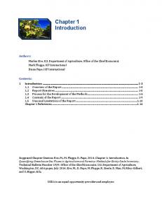
Procedure for Loop and Cluster Experiment Ge+ Implant 100keV(1x10’5/cm2) Into ( 100) Silicon
550°C Anneal ~~~r~~~~~
+ Boron
I %E? Implant
Baton
Implant
+ gjgL$ gPf$
30 min. or2hr.
I Anneal 8ZF - r
AtZeal
820~~
I Cluster Control
-t Cluster
E&p&merit
c Loop
I Loop IZxperiment Control
FIG. 1. Implantation and annealing schedule for (a) cluster detectors and (b) loop detectors.
and point-defect flux measurement by the type-11 dislocation loops. In this study, type-II “loop detectors” or “cluster detectors” were introduced into silicon via Ge+ implantation and annealing. These “detector” layers were subsequently used to study the point defects fluxes resulting from annealing low-dose B’ implants. By measuring loop area before and after the introduction of the B+ implant damage [with plan-view transmission electron microscopy (PTEM)] it was possible to determine quantitatively the concentration of interstitials, resulting from the B’- implant and anneal, that were trapped by the loops. Of the two “detector” types investigated, the loop detectors offer distinct advantages in terms of engineering flexibility, thermal stability, and trapping efficiency of Si interstitials. II. EXPERIMENT In all of the experiments, a single dose ( 1X 10¹⁵/cm2) of Ge+ at 100 keV was implanted at a 7” offset into (lOO), l-l.5 R cm, n-type silicon wafers at a beam current density of 0.17422 ,uA/cm2 using a Way flow@ end station. This resulted in the formation of a surface amorphous layer approximately 1400-1500 A thick, as measured by crosssectional TEM [Fig. 1). A. Cluster detector
formation
A subsequent furnace anneal at 550 “C for 16 h (in a dry Nz ambient) was used to regrow the amorphous layer by solid-phase epitaxy resulting in the formation of a layer 4816
J. Appl. Phys., Vol. 73, No. IO, 15 May 1993
FIG. 2. ?I-HRTEM views of (a) cluster detector layer using bright-field imaging (BF, g,, reflection) following a 550 “C ( 16 h) anneal; (b) cluster dislocation loop using multibeam imaging conditions (18 beams within the objective aperture field): (c) fulIy formed loop detector layer using BF imaging (g,,, reflection) following solid-phase-epitaxial regrowth at 550°C (16 h) and a post anneal at 800°C (2.5 h); (d) fully formed dislocation loop following the annealing schedule of (c) using multibeam imaging conditions (18 beams within the objective aperture field).
of type-II cluster detectors just below the original amorphous/crystalline (a/c) interface [Figs. 2 (a) and
Xb)l.
If the clusters were to be used as the detectors, then no further annealing was performed before the subsequent B+ implantation. The Bf implants were performed at doses of 7 X 10¹³/cm2, 1 X 10¹⁴/cm2, or 2 X 10i4/cmZ. This dose range was chosen because it is just below the dose regime where type-1 defects have been observed to form.14 A B+ implant energy of 30 keV was used so that the projected range of the B+ profile matched the depth of the type-II cluster layer. Next, an 800 “C furnace anneal for either 30 min or 2 h (in a dry N, ambient) was performed which resulted both in the coarsening of the clusters detectors into fully formed type-11 dislocation loops and the trapping of point defects arising from the B * implant. The loop coarsening is necessary to be able to quantify the interstitials trapped by the type-11 dislocations. All high-resolution TEM (HRTEM*) images were taken on a JEOL-4OOOFX TEM (1.95 A point-to-point resolution) using 18 beams within the objective aperture. B. Fully formed loop detector
formation
When fully formed type-II dislocation loops were to be used as detectors, it was necessary to perform a hightemperature anneal following the solid phase epitaxial regrowth step (at 550 “C) to coarsen the end of range damListebarger, Jones, and Slinkman
4816
Downloaded 04 Apr 2011 to 128.227.135.101. Redistribution subject to AIP license or copyright; see http://jap.aip.org/about/rights_and_permissions
age2 prior to 23’ implantation and annealing [Figs. 2(c) and 2(d)]. In an effort to determine optimal time/ temperature settings for this high-temperature anneal, the stability of the exkinsic type-II dislocation loops (as calculated by the number of atoms bound by the loops) were compared at 800 and 900 “C! for the period between 15 min and 5 h. In both the “cluster” and “loop” detector experiments, parallel control samples (without B+ implants) were prepared using Ge+-implanted material and identical annealing schedules. C. Determination
of interstitial
net flux
After completion of the final 800 “C annealing step, plan-view TEM samples were fabricated using standard IINCQ%F ( 3: 1) etching procedures. The dislocation loops were imaged using weak-beam dark-field (WBDF) and centered dark-field (CDF) two-beam g220conditions in a JELL-200C.X TEM. The mean number ,~i of interstitials trapped by the type-II dislocation loops was determined by randomly selecting a 2x2 cm* area on three different 50 008 j: PTEM negatives per implant sample. Within each of these regions, the diameter of each loop was measured along its longest axis (d) with a 15 ?(eye loop and the corresponding areas were calculated from A-n(di2)“. The total area was then divided by 3 to determine the mean area1 value k;. The loops were assumed to be circular in shape. This is a reasonable assumption for loops annealed at 800 “C based on tilting experiments. In a parallel study, the loops were reanalyzed using a computer image-processing station. 50 Ooox PTEM micrographs were mounted on a back-illuminating light table with the fields of interest projected onto a viewing cathode-ray tube (CRT) via a video camera. Type-II dislocation loop areal values were derived from computer-based “longest axis” calculations. By using either method, & could be expressed either as the percentage of the total area occupied by all of the type-11 dislocat.ion loops in this 2 x 2 cm’ region or as pi, the mean concentration of atoms/cm’ (trapped interstitials) bound by the dislocation loops. In this latter case, &/observed area was multiplied by the planar atomic density ( - 1.5x lot5 atoms/cm’) of the {l 11) plane to give Ffi Calculations for determining the net flux of interstitials trapped by the cluster or loop detectors after a specific Bf implantation condition were performed by subtracting the trapped interstitial concentration in the nonimplanted control sample from the value measured in the corresponding BJ;-implanted sample [see Figs. 3(a)-3 (d)]. The experimental error associated with the above calculations was determined by analyzing randomly selected 2x2 cm2 loop fields (at 50 000 x ) from the same sample. The total number of interstitials bound by the loops was determined for ten fields and the error was calculated as error = BJ,zii= 6.096, where ,vi is the mean number of interstitials trapped in the ten loop fields and o;, is the corresponding standard deviation. When similar calcuktions were performed assuming three loop fields per sample (as was the case in this study) 4017
J. Appl. Phys., Vol. 73, No. IO, 15 May 1993
FIG. 3. ITEM view (using WBDF, gz2,, reflectionj comparing type-II dislocation loops arising from (a) cluster detectors without a Bi implant and (bj with cluster detectors exposed to a (2X lO”/cm’) 30 keV B’ implant following a post anneal at 800°C (30 minj; (c9 loop detectors without a B’ implant, (dj compared with loop detectors exposed to a (2x: 10’4/cmZ) 30 keV B ’ implant following a final anneal at 800°C (2 h9.
the marrimum error was determined to be 8.0%. The “visibility” of the loops under varying TEM imaging conditions was also investigated as another source of error. Although type-II loops are considered to be perfect dislocations, TEM Burgers vector analysis determined that the quantity g*bxufO. Thus there was enough residual cont.rast to image all of the formed dislocation loops. III. RESULTS AND DISCUSSION The depth of the fully formed loop or cluster layer was determined from cross-sectional transmission electron microscopy XTEM [Figs. 2(a) and 2(c)] and was comparable in depth ( 1400-1500 A j to the projected range values predicted from ~~1~~88 calculations ( - 1282 A). The projected range of the B+ profile was measured with secondary-ion-mass spectroscopy (SIMS) and found to be -1150+5of%. The evolution of point defects and clusters into type-II dislocation loops following ion implantation/annealing has been discussed in previous studies.‘” Experimental data has demonstrated that. ion-implantation-induced point defects form in supersaturated condition and coalesce into small dislocation loops and clusters of point defects at temperatures up to -700 “C. At higher temperatures these clusters become thermally unstable. This results in their dissolution and/or condensation into type-II dislocation loops. Previous investigations of type-II dislocation loops from Ge’ implants (of energy ~60 keV9 have found them to be quite stable at 900 “C annealing temperatures for time peListebarger, Jones, and Slinkman
4817
Downloaded 04 Apr 2011 to 128.227.135.101. Redistribution subject to AIP license or copyright; see http://jap.aip.org/about/rights_and_permissions
--C --+---fr-
L,oops: after 8OO”c/ 120” anneal Clusters: after 8OO”C/30” anneal Clusters: after 8OO”C/ 120” anneal
1
2
Boron Dose (x 10’ 4 / cm2 > at 30 keV FIG. 4. A comparison of the net atom concentration trapped by the cluster detectors for a 30 and 120 min 800 “C anneal vs the loop detectors for a 800 “C, 2 h anneal, as a function of B+ dose.
riods up to 72 h.13 In our annealing time/temperature study, it was found that the concentration of atoms bound by type-II dislocation loops (e.g., loop diameter) fluctuated less than * 5% during the 800 “C! annealings; however, during the 900 “C! annealings, the variation in loop diameter was found to fluctuate by more than *25%. The erratic nature of the data collected for the 900 “C anneal cannot be fully explained, however, prolonged coarsening of the loops at this higher temperature may have contributed to inaccuracies in calculated interstitial values. Because of these fluctuations, in both the cluster and loop detector studies, the high-temperature anneal step(s) used in the “control” and Bf-implanted material was performed at 800 “C. Figures 3(a)-3 (d) are weak-beam dark-field PTEM micrographs comparing the “control” and B+-implanted type-II dislocation loops formed in the cluster and loop detector studies, respectively, following completion of the 800 “C annealing. In both experiments, it is obvious that some growth in the type-II dislocation loops has been induced upon annealing the B+ implant. In Fig. 4 the net concentration of atoms bound by the cluster detectors after coarsening (at 800 “C for 30 and 120 min) are compared for two different doses. These results show that the net flux of interstitials trapped by the cluster detectors was virtually identical for the two time periods used. This implies that the release of point defects resulting from Bf implantation and annealing is complete after 30 min at 800 “C, which is consistent with previous findings.lgl”’ Also in Fig. 4, the net flux of interstitials trapped by the loop and cluster detectors are compared for varying B+ dose conditions. Each curve represents the difference between type-II dislocation loops with the B+ implant and the corresponding “control” sample containing the type-II dislocation loops, but without the Bt implant. These results show that the number of interstitials trapped by both the cluster or loop detectors increases with increasing Bf dose. In addition, it is evident that the loop detectors are at 4818
J. Appt. Phys., Vol. 73, No. 10, 15 May 1993
least 20% more efficient in the “gettering” of interstitials. Though earlier studies 17J1have discussed the growth of type-II defects in response to oxidation and ion implantation, this is the first report of type-II defects being used as quantitative “detectors” of the flux of interstitials generated from ion implantation damage. In this study, type-II clusters and loops were formed and exposed to “controlled” levels of B+ implant damage to assess their efticiency as point-defect detectors. Because cluster detectors are so small, a stabilized diameter that can be easily measured cannot be achieved until the 800 “C annealing step has been completed. The release of most of the point defects from the B” implant also occurs after 15-30 min at 800 ‘C, thus, the final loop diameter is determined by competing sources of interstitials arising from both the initial Ge+ and the subsequent B+ implant. As a result of these complex and simultaneous interactions, interpretation of interstitial flux levels under varying B+ implant conditions is considerably more diflicult. In addition, because the clusters coarsen into loops upon annealing, it is not possible to use them for quantifying interstitials injected during high-temperature oxidation. In the loop detector study, our results showed that a stabilized loop layer could be engineered prior to the introduction of B’ implant damage, with the final loop diameter determined primarily by the point defects generated in the subsequent B+ implant and anneal processes. Thus, the loop detector protocol avoids the complex loop growth kinetics inherent in the cluster experiment while providing a methodology that is highly adaptable to point-defect studies involving both ion implantation and oxidation sources. The loop detectors also, as was noted, appear to be more efficient at gettering point defects. In this and other reports’” the smaller diameter and higher concentrations that are obtainable with type-II defects are responsible for their improved sensitivity to pointdefect disturbances compared to oxidation stacking faults; however, it is quite possible that variation in diameter and concentration among type-II clusters and loops is responsible for the observed difference in their respective trapping efficiencies. The importance of loop diameter in terms of loop stability has been calculated in a previous report.” These results suggest that the number of interstitials necessary to stabilize an extrinsic dislocation loop varies inversely with the loop radius. This could explain why the flux measured by the cluster detectors was less than the larger loop detectors. In addition, the diameter and density of the extended defects is certain to play a crucial role in determining by what mechanism {reaction-rate or diffusion-rate limited) point defects interact with both stacking faults and type-II dislocation loops. In a past report7 the interaction of point defects and extended defects was theorized to be reaction-rate limited, based upon the growth/shrinkage behavior of oxidation stacking faults (OSF). In this regime the stacking faults would have no influence on the surrounding saturated interstitial “environment” and increasing the OSF concentration resulted in no change in the growth rate. As stated Listebatger, Jones, and Slinkman
4818
Downloaded 04 Apr 2011 to 128.227.135.101. Redistribution subject to AIP license or copyright; see http://jap.aip.org/about/rights_and_permissions
in previous OSF studies, the fault density was typically 106!cm2. In the present study, the type-II defect concentrations were 10”/cm2 or four orders of magnitude higher than the OSF densities used in past oxidation experiments.7 Based on the results of previous work’7923 this increase in density appears to be sufficient evidence that the loops now significantly affect the point-defect concentration. This suggests that the interaction between point defects and dislocation loops is predominantly diffusion (rather than reaction-rate) limited. Additional experiments are in progress to discern if this indeed the case. Past repportsalso suggest that the loops are a barrier to impurity redistribution only if the impurity profile is between the loops and the surface.‘7~21923 This would imply that the loops are not effective in gettering interstitials beyond the loop layer. Based on this, it is unclear what fraction of the total point-defect flux is actually being measured. It will be necessary to place the loop layer at a depth deeper than the impurity profile in order to determine the total flux of point defects arising from the B+ implants. This experiment is also in progress. IV. CONCLUSIONS It has been shown that by using Ge+ ion implantation it is possible to introduce a controllable layer of type-11 dislocation loops which can be used as very sensitive pointdefect detectors in silicon. The net point-defect fluxes trapped by the type-11 dislocation loops upon low-dose Bf implantation and annealing have been quantitatively determined to be very similar to the dose, when the type-II damage and the B” projected range are similar. Fully formed dislocation loops have been shown to be quite stable at 800 “C and are more sensitive than cluster detectors. Finally, it is helieved that the point-defect-dislocation-loop interactions may be diffusion limited, implying that it should be possible to determine how the net flux of point defects varies with implant conditions. Such data will be very valuable in improving the process modeling of advanced microelectronic devices.
4819
J. Appb Phys., Vol. 73, No. 10, 15 May 1993
ACKNOWLEDGMENTS The authors wish to thank IBM, Inc: and the NSF (P.Y.I. Program) for their support of this research, and Steve Schein (at the University of Florida’s SURGE facility) for his assistance in ion implantation.
‘A. E. Michel, W. Rausch, P. A. Ronsheim, and R. H. Kastl, Appl. Phys. Lett. 50, 416 (1987). ‘P. A. Packan and J. D. Plummer, Appl. Phys. Lett. 56, 1787 (1990). 3H. Park, M.S. thesis, University of Florida, 1991. 4P. M. Fahey, P. B. Griffin, and J. D. Plummer, Rev. Mod. Phys. 61,289 (1989). 5M. Law, C. F. Rafferty, and R. W. Dutton, in International Electron. Devices Meeting, Los Angeles, 1986. 6M. E. Law, and J. R. Pfiester, IEEE Trans. Electron. Devices ED-38, 278 (1991). ‘D. A. Antoniadis, J. Electrochem. Sot. 129, 1093 ( 1982). s K. S. Jones (private communication). ‘P. Fahey, R. W. Dutton, and M. Moslehi, Appl. Phys. Lett. 43, 683 (1983). ‘OP. Fahey, R. W. Dutton, and S. M. Hu, Appl. Phys. Lett. 44, 777 (1984). “P Fahey, G. Barbuscia, M. Moslehi, and R. W. Dutton, Appl. Phys. Lktt. 46, 784 (1985). ‘*P. Fahey, S. S. Iyer, and G. J. Scilla, Appl. Phys. Lett, 54, 843 ( 1988). 13K. S. Jones, Ph.D thesis, University of California, 1987. 14K. S. Jones, S. Prussin, and E. R. Weber, Appl. Phys. A 45, 1 ( 1988). ‘sK. S. Jones and D. Venables, J. Appl. Phys. 69, 293 1 (1991). 16M. Servidori, 2. Sourek, and S. Solmi, J. Appl. Phys. 62, 1723 (1987). “T 0. Sedgwick, A. E. Michel, V. R. Deline, S. A. Cohen, and 3. B. Lasky, J. Appl. Phys. 63, 1452 (1988). 18H. L . Meng, S. Prussin, M. E. Law, and K. S. Jones (private communication) . “A. E. Michel, W. Rausch, and P. A. Ronsheim, Appl. Phys. Lett. 51, 487 (1987). ‘ON
E B Cowern,
K. T. F. Janssen, and 33. F. F. Jos, J. Appl.
Phys. 68,
6191’(1990). 21Y. Kim, H. Z. Massoud, S. Chevacharoeukul, and R. B. Fair (private communication). “W. D. Nix and H. G. Robinson (private communication). “Y. M. Kim, G. Q. Lo, and D. L. Kwong, Appl. Phys. Lett. 55, 2316 (1989).
Listebarger, Jones, and Slinkman
4819
Downloaded 04 Apr 2011 to 128.227.135.101. Redistribution subject to AIP license or copyright; see http://jap.aip.org/about/rights_and_permissions