The paper explains fault detection of ungrounded distribution systems and the issue .... oidal current transformer is not available, system protection can use the ...
1
Deterministic High-Impedance Fault Detection and Phase Selection on Ungrounded Distribution Systems Daqing Hou and Normann Fischer, Schweitzer Engineering Laboratories, Inc. Abstract— Downed conductors, tree branches touching conductors, and failing insulators often cause high-impedance faults in overhead distribution systems. The fault currents of these faults are much smaller than detection thresholds of traditional ground fault detection devices, so reliable detection of these highimpedance faults is challenging. Although fault currents can be much smaller in ungrounded systems than fault currents in multigrounded systems given similar fault conditions, fault detection for ungrounded systems is nevertheless easier. This paper contrasts the differences between high-impedance fault detections for ungrounded and multigrounded systems. The paper explains fault detection of ungrounded distribution systems and the issue of fault detection sensitivity. The paper also introduces a recent advance in faulted phase selection on these ungrounded systems and demonstrates this advance through a staged fault test example from a utility.
I. INTRODUCTION High-impedance faults (HIF) are short-circuit faults with fault currents smaller than what a traditional overcurrent protective relay can detect. HIFs are the main concern for medium-voltage overhead distribution systems with voltage levels less than 35 kV. On power transmission systems where voltage levels are 64 kV and greater, the systems are commonly grounded and a ground fault normally generates large enough currents to operate protection devices even if large fault impedance is involved. The main causes of HIFs are tree branches touching a phase conductor, failing or dirty insulators that cause flashovers between a phase conductor and the ground or downed conductors. Almost all HIFs involve the ground directly or indirectly. Staged downed-conductor fault tests in North America indicate that downed-conductor HIFs generate quite small fault currents. For ungrounded systems, fault current magnitude depends on the type of ground surfaces and system stray capacitance. The ground fault current of ungrounded systems is normally in a range of milliamps to several amperes. The HIF current of multigrounded systems depends highly on the surface types upon which a conductor falls, and the fault current varies from zero to less than 100 amperes. Because of small fault currents, HIFs generally do not affect distribution system operations. HIFs cause minor, localized damage to utility equipment. Utilities incur only small direct cost associated with repairing a damaged line. The cost of improved HIF detection is highly unlikely to be justified by
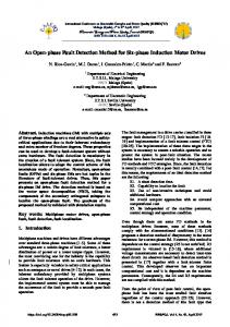
a conventional cost/benefit analysis. The primary motivation for detecting and clearing HIFs is to improve public safety. System grounding methods heavily influence ground fault detection [1]. Although the high-impedance ground fault current of ungrounded systems can be much smaller than that of multigrounded systems, the high-impedance fault detection of ungrounded systems can be more reliable and deterministic than the fault detection of grounded systems. In this paper, we first review ground fault detection for ungrounded and multigrounded distribution systems. The review should help in providing an understanding of why different systems need dramatically different high-impedance fault detection techniques and how these techniques affect fault detection reliability. We then concentrate on high-impedance fault detection of ungrounded systems. We review sensitive directional overcurrent protection and discuss ways to improve fault detection sensitivities. We introduce a new faulted phase selection method that works reliably under very high fault impedance. Finally, we provide an example of staged fault tests from one utility that demonstrates fault detection and faulted phase selection results. II. DETECTING HIGH-IMPEDANCE GROUND FAULTS OF UNGROUNDED SYSTEMS VERSUS MULTIGROUNDED SYSTEMS Because no intentional neutral groundings exist in ungrounded systems; the ground fault current of such systems is quite small. There is a misconception that it is more difficult to detect high-impedance faults on ungrounded systems than on multigrounded systems. This section compares the structures of ungrounded and multigrounded systems, introduces general ground fault detection methodologies for each system, and concludes that high-impedance fault detection for ungrounded systems can be more deterministic and reliable than for multigrounded systems. Fig. 1 shows a typical ungrounded distribution feeder. This feeder has the benefit of not having a neutral conductor running throughout the system. Fig. 1 shows phase-to-phase and phase-to-ground distributed capacitances that primarily determine ground fault current magnitude and unbalance residual current under normal system operations. All loads are connected phase-to-phase, and the load unbalance induces no residual current. The normal residual unbalance in the system results mainly from the uneven distribution of capacitance. This so-called standing residual unbalance is normally quite small.
2 A N
CAB
CCA Load
G
Ground fault B
CBC C CC
CB
CA
A
G
Fig. 1.
N
Ungrounded power system
The large capacitive impedance of ungrounded systems limits ground fault current and has virtually no effect on the phase-to-neutral voltage of the faulted phase. The major wellknown benefits of ungrounded systems, such as low thermal stress, better personnel safety, and more reliable load service, come from this limited ground fault current. Fig. 2 shows the phase-to-phase and phase-to-ground voltages for a ground fault condition. The uncollapsed voltage triangle during a ground fault means that the system can operate normally in the presence of a single line-to-ground fault. Nevertheless, it is desirable to detect the ground fault as quickly as possible because the increased voltage level on the unfaulted phases makes it easy for the fault to evolve into a multiphase fault. Because single line-to-ground faults make up approximately 80 percent of all faults on a power system, we can see that power interruptions because of faults seldom occur. This characteristic of ungrounded systems makes these systems popular in industrial systems and some regions of the world. On the other hand, limited ground fault current can cause difficulties with ground fault protection on these systems. VAG
VCA
VAB G
N,G
VCG
VBC
VBG
VCA
VAB N
VCG = VCA
rent as small as several milliamps secondary. An available sensitive directional overcurrent protection, which we discuss in more detail in the next section, uses the fundamental frequency component of the residual current and benefits from the fact that phase-to-phase connected loads do not introduce residual current and the standing residual current from system stray capacitance is small. Microprocessor relays have satisfactorily detected downed-conductor high-impedance faults on such unfavorable ground surfaces as soil and concrete.
VBC
VBG = –VAB
Fig. 2. Voltage triangle of a normal ungrounded system and one with a ground fault
When relay current measurement sensitivity is low, traditional ground fault protection uses zero-sequence overvoltage. However, because the voltage condition does not pinpoint which feeder is faulted, the system operator has to manually open each feeder on a bus sequentially to find the faulted feeder. Modern microprocessor relays are more sensitive than traditional electromechanical relays. The sensitive current channels in modern microprocessor relays can measure a cur-
Load
G
Ground fault B
Load
C Neutral conductor
G Fig. 3. Multigrounded system
Fig. 3 shows a typical four-wire multigrounded distribution feeder. The neutral wire is typically grounded at each distribution transformer point to eliminate potential rise on this wire. Service loads can be more flexibly connected as either phaseto-phase or phase-to-neutral. The system standing residual current comes from load unbalance. When a solid-ground fault occurs, residual current that relays measure at the substation contains both load unbalance and fault current. Grounded distribution systems are possibly unbalanced because a majority of the loads for these systems are of a singlephase nature. Even worse, the amount of load unbalance is dynamic and changes according to time of day and variations in system operation conditions. As a consequence, utility engineers must consider the worst system load unbalance when they set pickup values for a ground relay. This worst load unbalance, together with concerns about cold load pickup, transformer inrushes, and coordination with downstream ground relays, makes ground relays unsuitable for high-impedance fault protection. Many utilities have eliminated the use of all ground relays because of unpredictable load unbalances. For those utilities that do use ground relays, a survey [2] indicates that engineers most often set the pickups of ground relays as a percentage of phase relay pickups. The protection functions of these ground relays for high-impedance faults are therefore diminished. To detect high-impedance faults combined with unbalanced loads, power system personnel routinely use current components other than fundamental frequency to look for arcing signatures normally involved with these faults. Many new techniques, including expert systems, neural networks, wavelet decomposition, and hypothesis testing, are in use. We measure successes in detecting high-impedance faults through use of some of these techniques in the statistical sense.
3
III. HIGH-IMPEDANCE FAULT PROTECTION FOR UNGROUNDED SYSTEMS Fig. 4 shows an ungrounded power system with a solid Aphase-to-ground fault on Feeder 3. We can observe from the figure that fault current (IF) depends on line-to-ground capacitance of the unfaulted power system phases. This dependency highlights an important difference between a single line-toground fault on a multigrounded system and a fault on an ungrounded power system. In a multigrounded power system, series impedance dictates the magnitude of the fault current. In an ungrounded power system, however, shunt impedance dictates the magnitude of the fault current. Fig. 5 shows typical connections of instrument transformers and a protective device for an ungrounded network. Voltage instrument transformers consist of two types. The first is an open delta voltage transformer that a particular feeder uses for functions such as determining direction for multiphase feeder faults and determining the active and reacA
tive power supplied to the load. The second type is a broken delta transformer that supplies all protective feeders on the bus with residual voltage to determine the direction of a ground fault; maintenance staff can also use this voltage to alert them to a ground fault on the power system. Another innovative voltage transformer connection is available that uses one set of voltage transformers to obtain both residual and phase voltages and, at the same time, provides a loss-of-potential detection possibility [3]. The current instrument transformers can consist of two types: the normal phase current transformers used by the traditional multiphase overcurrent relay and a toroidal current transformer used by the ground fault detection logic. If a toroidal current transformer is not available, system protection can use the residual current from the phase current transformers to measure the residual current in the feeder; however, this measurement does not afford the protective device the same sensitivity as measurement from a toroidal current transformer. B C
Relay 1 Feeder 1
Relay 2
CAG
IB1
IC1
CBG
CCG
Feeder 2
Power System CAG
IB2
IC2
CBG
CCG
Relay 3 Feeder 3
CAG
Fig. 4.
An ungrounded power system with an A-phase-to-ground fault on Feeder 3
IB3
IC3
CBG
CCG
Fault
IF
4
have a standing unbalance because of power line asymmetry. Fig. 2 also shows the voltage phasor diagram for the same power system during a solid A-phase-to-ground fault. We can observe the angular relationship between the residual voltage and current by superimposing the fault current phasor diagram on top of the fault voltage phasor diagram, as in Fig. 6.
Busbar
A B C
IB1 Protective Device
IB2 G
IF
IB3 IC3 IC2
* Preferred
IC1
VCG = VCA
VBG = –VAB
Breaker
3V0 Fig. 6. Angular relationship between the residual voltage and current for an A-phase-to-ground fault
Feeder Fig. 5. Typical instrument transformer connections to a protective device for an ungrounded power system
A. Identifying the Faulted Feeder If we now go back and analyze the single line-to-ground fault represented in Fig. 4, we would typically start with the voltage profile of the system. Fig. 2 shows the prefault voltage phasor diagram of the power system. Note we assume the system has no standing unbalance; usually protection systems
From Fig. 6, we can see that the fault current (IF) lags the residual voltage (3V0) by 90 degrees. However, because it is not possible to determine the fault current (IF) from a single protective device and this information alone will not indicate the faulted feeder, let us break up the fault current as seen by each individual feeder and then compare that current to the residual voltage. Fig. 7 shows the fault current flowing through each individual feeder referenced to the residual voltage of the system.
IB1 , IB2
IB3 IF
G
IN3
G IN1, IN2 IC3
VCG
IC1 , IC2
VBG
VCG
3V0 3V0 Feeder 3 Feeders 1 and 2 (faulted feeder) (unfaulted feeders) Fig. 7. Residual current flowing through the faulted and unfaulted feeders as compared to the residual voltage
VBG
5
XCsys1
V1A
Zload1 ZS1
m • Zline1
Ztrfr1
(1–m) • Zline1 3Rf
XCsys2
Zload2
ZS2 m • Zline2
Ztrfr2
XCsys0 ZS0 Ztrfr0
Fig. 8.
(1–m) • Zline2
XCline0
V0 m • Zline0
Zload0
(1–m) • Zline0
I0 Equivalent sequence diagram for an A-phase-to-ground fault on an ungrounded system
In analyzing the faulted feeder phasor diagram in Fig. 7, we can say that, for the faulted feeder case, the neutral or residual current (IN3) lags the residual voltage (3V0) by 90 degrees. In reality, the lag will be less than 90 degrees because of the conductance (G) of the feeder. However, the effect of the conductance is relatively small and can be ignored for all practical purposes. In analyzing the phasor diagram of the unfaulted feeders, one can see that the residual currents (IN1 , IN2) lead the residual voltage (3V0) by 90 degrees. From this observation, one can say that the fault is in front of the relay measuring point if the residual current lags the residual voltage by 90 degrees and the fault is behind the relay measuring point if the residual current leads the residual voltage by 90 degrees. To examine this relationship when fault resistance is introduced as in high-impedance fault situations, let us examine a sequence diagram for a single-line-to-ground fault on an ungrounded power system. Fig. 8 shows the exact equivalent sequence diagram, excluding the system conductance (G). If we examine the zero-sequence circuit more closely, we observe that the source impedance primarily consists of the zero-sequence capacitance of the power system. Therefore, for forward faults, the angular relationship between current and voltage will always remain constant regardless of fault resistance. This means that for a forward fault the residual current will always lag the residual voltage by 90 degrees. The influence of the fault resistance is that it will reduce the magnitude of the residual current and voltage. For a reverse fault, the protective device would measure the impedance in front of the relay. This impedance is the sum of the zero-sequence impedance and the zero-sequence capacitance of the line\feeder, but the line impedance when compared to the zero-sequence capacitance is negligible. Therefore, once again the fault resistance has no influence on the angular relationship between residual voltage and current. Residual current will always lead residual voltage by an angle that is very close to 90 degrees for a reverse fault.
By simply comparing residual voltage to residual current, one can identify the faulted feeder. If residual current leads residual voltage, the fault is behind the relay measuring point. If residual current lags residual voltage, the fault is in front of the relay measuring point. B. Identifying the Faulted Phase Once the faulted feeder in the power system has been identified, it is desirable to identify the faulted phase. To achieve this purpose, let us re-examine the sequence diagram for a single line-to-ground fault on an ungrounded power system shown in Fig. 8. We can simplify this sequence diagram by considering the following: The impedance of XCsys1 is much greater (on the order of 100 times) than the sum of ZS1 and Ztrfr1 [XCsys1 >>ZS1+Ztrfr1]; this means one can ignore the effect of XCsys1. The impedance of XCsys2 is much greater than the sum of ZS2 and Ztrfr2; this means one can ignore the effect of XCsys2. The impedance XCsys0 is much greater than the sum of ZS1, ZS2, Ztrfr1 and Ztrfr2, [XCsys0 >> ZS1 +ZS1+Ztrfr1 + Ztrfr1]. From the above considerations, we can neglect positiveand negative-sequence impedance and reduce the sequence diagram of Fig. 8 to that of Fig. 9. If we now examine Fig. 9 carefully, we will see that for a forward fault the residual current (I0) leads the positive sequence voltage (V1A) by 90 degrees, but the above diagram is for an A-phase-to-ground fault with the A-phase as a reference in calculating the value of the positive-sequence voltage V1. To modify Fig. 9 so that it can apply to a B-phase-to-ground and a C-phase-to-ground fault while maintaining the A-phase used as the reference quantity in the positive-sequence voltage calculation, we need to phase shift the zero-sequence voltage by the appropriate (1∠120°) factor. If we now redraw the reduced sequence diagram shown in Fig. 9, we obtain a sequence diagram that addresses the question of how to modify
6
Fig. 9. Fig. 10 illustrates sequence diagrams for the different single-phase-to-ground faults.
V1A
3Rf XCsys0
C-phase-to-ground fault, I0, lags V1A by 150 degrees. By analyzing the same sequence diagram again, this time for a single-line-to-ground fault behind the relay measuring point, we can state the following: A-phase-to-ground fault, I0, lags V1A by 90 degrees. B-phase-to-ground fault, I0, leads V1A by 150 degrees. C-phase-to-ground fault, I0, leads V1A by 30 degrees.
XCline0
If we now draw a phasor diagram of the previous statements, we obtain the phasor diagrams shown in Fig. 11.
V0
Forward Ground Faults V1A
I0 Fig. 9. Reduced sequence diagram for an A-phase-to-ground fault on an ungrounded system
VAG
I0B
V1A I0A 1: 1
VCG
V0
XCsys0
XCline0
VBG
3Rf V1A
I0 I0C
A-Phase-to-ground fault
I0C
VAG
V1A I0A 1 : 1 ∠ − 120°
V0
XCsys0
XCline0
3Rf
I0 B-Phase-to-ground fault
V1A
1: 1 ∠120°
V0
XCsys0
XCline0
3Rf
I0 C-Phase-to-ground fault Fig. 10. Reduced sequence diagrams for single-line-to-ground faults on ungrounded systems
If we now analyze the sequence diagrams in Fig. 10, we can state the following with regard to single-line-to-ground faults in front of the relay measuring point: A-phase-to-ground fault, I0, leads V1A by 90 degrees. B-phase-to-ground fault, I0, lags V1A by 30 degrees.
VCG
VBG
I0B Reverse Ground Faults Fig. 11. Phasor diagram for solid single-line-to-ground faults for fault in front of the relay measuring point and behind the relay measuring point, referenced to the positive-sequence voltage (V1A)
To examine how the above-described relationship behaves when fault resistance increases, let us again analyze the reduced sequence diagram shown in Fig. 9 and increase the fault resistance for an A-phase single-line-to-ground fault in front of the relay measuring point. Fig. 12 represents the phasor relationship between the positive-sequence voltage (V1A), the residual current (I0) and the residual voltage (V0) for three different fault resistances, namely: Rf > XCΣ0 Where XCΣ0 is the total zero-sequence capacitive impedance.
7
V1A
V1A
V1A
Single line to ground faults in front of relay measuring point
VAG I0 I0
V1A
I0
VAG
VAG
0° –5°
V0
–25°
Rf >> XC Σ0
I0B
V0 3Rf = XC V0 Σ0 Rf