Proceedings of the World Congress on Engineering 2015 Vol I WCE 2015, July 1 - 3, 2015, London, U.K.
Developing a Method with an Experimental Study for Estimating Vehicle Speed and Slip using Kalman Filter and Fuzzy Rules Ali Momeni, Seyed Reza Moasheri, Hossein Chabok, and Arman Kheradmand �
Abstract— vehicle slip rate is directly dependent on vehicle speed. Most current slip control systems rely on vehicle speed. This means that the estimation of the accurate vehicle speed, cause better control of vehicle stability. In some of slippery roads vehicle speedometer systems will not be able to estimate true vehicle speed, because non-driven wheels are locked while the car ambulates. This paper presents a developed method with an experimental study for estimating vehicle speed using Kalman filter and fuzzy rules. The maximum real error of the system is approximately 0.18 m/s in different conditions of driving. Index Terms— Experimental study, Fuzzy logic, Kalman filter, Offset estimation, Vehicle speed
Nomenclature
a m = Measured acceleration, m / s 2 v = Vehicle velocity, m / s v m = Measured vehicle speed, m / s v w = Wheels velocity, rad / s Vˆm = Filtered Integrated Vehicle velocity, m / s aˆ m = Filtered measured acceleration, m / s Vˆw = Filtered wheels velocity, rad / s Vˆt = True vehicle speed, m / s Sˆt = True vehicle slip R = Kalman filter coefficient a0 = Acceleration offset, m / s 2 a0e = Offset that estimated by Kalman filter, m / s 2 a0n = Acceleration offset in normal state, m / s 2 S = Small mode in fuzzy rules M = Medium mode in fuzzy rules L = Large mode in fuzzy rules w1 , w 2 = Process noise w v = Measurement noise Manuscript received March 03, 2015; revised April 15, 2015. This work was supported by the KISH JUNOUB TADAROK company of Iran. A.Momeni is with the department of electrical and electronics, Shiraz university of technology, Shiraz 13876-71557, Iran (e-mail:
[email protected]). S.R.Moasheri is with Education Organization of Razavi Khorasan, Education Ministry, Mashhad, Iran (e-mail:
[email protected]). H.Chabok is with the department of electrical and electronics, Shiraz university of technology, Shiraz 13876-71557, Iran (e-mail:
[email protected]). A.Kheradmand is with the department of electrical and electronics, Shiraz university of technology, Shiraz 13876-71557,I ran (e-mail:
[email protected]).
ISBN: 978-988-19253-4-3 ISSN: 2078-0958 (Print); ISSN: 2078-0966 (Online)
I. INTRODUCTION
T
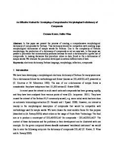
he vehicle speed is one of the most important factors to determine the exact amount of vehicle slip. Vehicle speed and slip rate have a direct relationship with each other. Accurate speed of the car has an effective influence on the vehicle speed estimation by applying Kalman filtering algorithm braking systems such as ABS and TCS [1]. In most cars, the vehicle speed can be achieved from non-driven Wheels. In normal state vehicle speed and wheels speed are equal however in abnormal state when the car is skidding on a slippery road, vehicle speed cannot be taken directly from the vehicle speed [2]. In [3, 4], studies are based on a complex modeling and simulation and also an abroad and lengthy Kalman filter for estimating vehicle speed were applied. In [5], vehicle speed estimated using Kalman filter and fuzzy logic rules but they did not present acceleration offset and its effect on the accuracy of vehicle speed estimation. Some methods such as [6], used GPS system or, estimate vehicle speed using camera or video data as [7]. But these methods are not economic and most cars are not equipped with them. Furthermore camera fixed outside the car, cannot calculate the speed of the vehicle in all conditions. In [8], a method for estimating vehicle speed with consideration of acceleration offset is presented, but acceleration offset values in sudden break is not modeled and assessed. In this paper, based on our previous work [8], we proposed a system to estimate vehicle speed in different conditions of driving and also we established an updating method of acceleration offset and a linear model for obtaining acceleration offset in sudden break. This method is based on a Kalman filter estimation model and fuzzy logic. Using fuzzy relations, we specify Kalman filter in every moment to estimate vehicle speed in different conditions of driving such as normal state, sudden break and road ramp mode. This system estimates the exact speed of the car in different situations and also estimates vehicle slip more accurate due to the accuracy of the vehicle speed. This system can be easily installed on each car. The proposed syestem scheme is shown in figure 1. All conclusions are based on observations and experimental tests. This paper is organized as follows: section 2 defines basic speed estimation model for Kalman filtering algorithm. Fuzzy rules for adjusting Kalman filter coefficients are presented in section 3. In section 4 experimental results in both normal and abnormal states described and discussed in detail. In section 5 slip
WCE 2015
Proceedings of the World Congress on Engineering 2015 Vol I WCE 2015, July 1 - 3, 2015, London, U.K. estimation results presented and finally, the work is concluded in section 6.
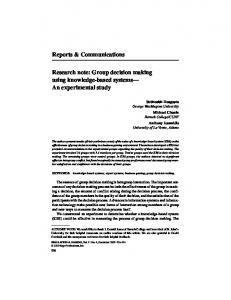
A. Adjustment R The Kalman filter coefficient (R), as a variable parameter, is necessary to change in different conditions of driving to estimate vehicle speed and handle slip or skid. Figure 2 shows the surface of fuzzy rules. Fuzzy rules may define as:
K i � �S , MS , ML , L� � 1 , If
a 0 e � a0 n
�
max a0 e , a0 n
�
is K i and
i � 0,1, 2 Vˆm � Vˆw max Vˆm , Vˆw
�
�
is K i then a0 � a0n
Fig.1 The proposed syestem scheme
II. VEHICLE SPEED ESTIMATION BY APPLYING KALMAN FILTERING ALGORITHM Kalman filter is used for eliminating the noise in the original values. To evaluate the performance of the filter we have following state-space description. v� � a m � a 0 (1) a� 0 � 0
Fig.2 Surface of fuzzy rules
where v, a m and a 0 are the vehicle speed, measured acceleration and acceleration offset respectively. By discretization of the equation (1), we have discrete statespace model (2). � v ( k � 1) � � � 1 - d � � � v ( k ) � � � d � � a ( k ) � � w1 ( k ) � m �� a 0 ( k � 1) �� �� 0 1 �� �� a 0 ( k ) �� �� 0 �� �� w 2 ( k ) �� (2) vm ( k )
�
� 1
0
� �� av ((kk)) �� � wv ( k ) �
0
�
In this model, dT is sampling period, w1 and w2 refer to process noise, wv is measurement noise and vm is measured vehicle speed. We can estimate vehicle speed and acceleration offset by applying Kalman filter algorithm to estimation model (2), where w1 , w2 and wv are as zeromean white noise.
Fig.3 Member ship function
B. Adjustment a0 as the output offset of fuzzy logic III. FUZZY RULES FOR ADJUSTING KALMAN FILTER COEFFICIENT TO ESTIMATE ACCURATE VEHICLE SPEED
Occurrence of skid or slip can be easily discriminated from the difference measurements between Vˆm vehicle velocity and Vˆ wheels velocity [6]. We considered that by w
changing R (k ) Kalman filter coefficient and a 0 acceleration offset, better offset estimation of vehicle speed can be derived in different conditions. With the knowledge that R is the covariance matrix of the process noise and by tuning them, noise in a sampling process can be eliminated, the fuzzy rules are as follows:
According to the figure 1, a 0 is the output acceleration offset of fuzzy logic. TSK Fuzzy rules specify true value of a0 for Kalman filter estimator in different driving situation and they can be defined as follow: a. Normal state and ramp road When the car is in a normal mood and vehicle and wheels velocity are the same, fuzzy rules can be described as follows:
K i � �S , MS� � 1 , If
a0 e � a0 n
�
max a0 e , a0 n
ISBN: 978-988-19253-4-3 ISSN: 2078-0958 (Print); ISSN: 2078-0966 (Online)
�
i � 0,1
is K i and
Vˆm � Vˆw is K i then a0 � max Vˆm , Vˆw
�
�
a0e WCE 2015
Proceedings of the World Congress on Engineering 2015 Vol I WCE 2015, July 1 - 3, 2015, London, U.K. where
aoe is the output offset of Kalman filter. As shown
in Figure 5, our experimental studies show that aon , offset in normal state, is equal to 0.065
m s2
.
c. Vehicle takeoff mode As an example, when the vehicle gets stuck in a sandy road or at the start of the running toward, wheels velocity increase and acceleration decreases. Fuzzy rule set as:
K i � �S , MS� � 1 , If
i � 0,1
Qi � �ML, L� � 1 ,
i � 0,1
Vˆm � Vˆw is Qi and aˆ m is K i and Vˆm is K i then a0 max Vˆm , Vˆw
�
�
� a0n
IV. EXPERIMENTAL STUDIES ON VEHICLE SPEED ESTIMATION Sudden break Normal state
Fig5. Offset of acceleration measurement in normal state and abnormal sudden break
b. Sudden break In sudden break there is a problem for obtaining acceleration offset. If we trace acceleration offset via acceleration multiplied by vehicle speed, we can achieve acceleration offset values more accurate. According to equation 3 and figure 6 we have fitted an approximate linear model on results. Where constant values P1=-0.000303 and P2=0.13414, RMSE=0.0021 obtained from experimental results. (3) offset ( t ) � P1 � � a (t ).v ( t ) � � P2
To quantify the performance of the new method in both normal and abnormal state field tests were performed on a rear-wheel drive car. Wheel velocity was achieved from a rotary shaft encoder. The wheel-based vehicle speed is obtained by multiplying the wheel rotation speed on the normal radius of the wheel. An ADXL345 EVALUATION BOARD accelerometer sensor utilized for obtaining vehicle acceleration. Figure 7 shows the experimental tested car. Field Experimental tests were done in two parts: normal state and sudden break. The first part is when the car is not faced with an unusual situation. It would be mentioned that all braking maneuvers were performed on a straight line.
Fig.7 Experimental tested vehicle
A. Experimental studies on vehicle speed estimation (in normal state)
Fig.6 sudden break acceleration offset linear model
When driver suddenly breaks, offset and difference between vehicle speed and wheels velocity increase. Fuzzy rules can be expressed as follows:
K i � �S , ML� � 1 , If
a 0 e � a0 n
�
max a0 e , a0 n
�
i � 0,1
is Ki and
Vˆm � Vˆw max Vˆm , Vˆw
�
�
is K i then a0 � Eq.3
ISBN: 978-988-19253-4-3 ISSN: 2078-0958 (Print); ISSN: 2078-0966 (Online)
The test vehicle is driven straight with alternate acceleration and breaking. In order to test the system response, the comparison between system estimated and the real speed is performed. As mentioned by applying Kalman Filter algorithm, vehicle speed and the acceleration offset can be estimated. Figure 8 shows vehicle acceleration during experiment. As it is observed the received signal, due to the vibration of the vehicle or excess errors by derivative operation, is surrounded by a lot of noise. A low pass band filter of 0-15.3 Hz is applied to remove noise from the desired signal. For computing the amount of missing data by filtering process, root-mean-square error (RMSE) of acceleration is calculated. According to equation 4, MSE and RMSE values are 0.0241 and 0.1552, respectively. Figure 9 shows the filtered vehicle acceleration as one of the inputs of Kalman filter estimation model according to the schematic diagram of the whole system.
WCE 2015
Proceedings of the World Congress on Engineering 2015 Vol I WCE 2015, July 1 - 3, 2015, London, U.K. 14 real velocity estimated velocity
12
velocity, m/s
10 8 6 4 2 0 -2
Fig.8 Vehicle acceleration
0
E i � filtered _ acceleration ( aˆ mi ) � true _ acceleration ( ati ) n
MSE � RM SE �
2 i
(4)
n MSE
B. Experimental studies on vehicle speed estimation (in abnormal state) Field tests in abnormal conditions were also examined. With similar characteristics in terms of straight-line tests were performed. This time, vehicle suddenly breaks, and in this case, the vehicle speed cannot be obtained directly from the wheels velocity. Figure 12 shows the tremendous difference between vehicle wheel velocity and actual velocity. The proposed system estimates actual vehicle velocity more accurate as shown in figure 12. Slip, acceleration offset and the estimated speed consequences discussed in this section.
ISBN: 978-988-19253-4-3 ISSN: 2078-0958 (Print); ISSN: 2078-0966 (Online)
6
8
10 time,s
12
14
16
18
20
Fig.11 Speed estimation error
The estimated vehicle velocity is showed and is compared with the real velocity in Figure 10. The actual velocity was taken out by speedometer camera. It is clear that the real speed and estimated speed do not have much difference and almost are equal. Figure 11 shows the speed estimated error and the maximum error of the system approximately is 0.1m/s.
i �1
4
Fig.10 Comparison of real velocity and estimated velocity
Fig.9 Filtered vehicle acceleration
�E
2
C.
Acceleration offset estimation
In normal situations vehicle speed can be estimated from wheels speed, however, in abnormal state vehicle velocity cannot be derived from wheels speed. Vehicle speed cannot be obtained by direct integration of acceleration data. Due to the integration process, there is a constant value called acceleration offset that may change with integration unremitting operation. Also changes with vehicle movement and shocks and abnormity states of the road. These ongoing variations will occur in integrated values and cause imprecise velocity. The offset is not considered in some researches and even gets waiver but here we paid special attention to the offset variations. As shown in Figure 1, acceleration offset will be updated using Kalman filter and percentage error in estimating the actual vehicle speed will be reduced. Table I, shows acceleration offset values in both normal state and sudden break. The point is that in abnormal conditions the estimated offset ( a 0 e ) is not correct that’s why we consider the constant offset that was measured in unusual condition experiment as acceleration offset in abnormal condition ( a0s ).
WCE 2015
Proceedings of the World Congress on Engineering 2015 Vol I WCE 2015, July 1 - 3, 2015, London, U.K. 16 wheel velocity estimated velocity real velocity integrated acceleration
14
Speed estimation (m/s)
12 10
integrated acceleration estimated velocity
8 6 4
real velocity wheel velocity
2 0 -2
0
2
4
6
8
10
12
14
time (s)
Fig. 12 Vehicle speed estimation in abnormal state 6 direct method proposed method
Speed estimation error (m/s)
5
[2] 4
3 direct method 2 [2]
1
0 proposed method 2
0
4
6
8
12
10
14
time (s)
Fig13. Vehicle speed estimation in comparison with reference [2] 100
Slip estimation (%)
80 60 40 20 0 -20
0
2
4
6
8
10
12
14
16
time (s)
Fig14. Percentage of vehicle slip
ISBN: 978-988-19253-4-3 ISSN: 2078-0958 (Print); ISSN: 2078-0966 (Online)
WCE 2015
Proceedings of the World Congress on Engineering 2015 Vol I WCE 2015, July 1 - 3, 2015, London, U.K. [4]
TABLE I DEFINE OFFSET VALUE
Symbol
Quantity
Offset value
a0 n
Acceleration offset in normal state
0.065 m/s2
a0 s
Acceleration offset in sudden break
[5]
[6] According to equation 3 [7]
a0e
Offset that estimated by Kalman filter
According to Kalman equation 2 [8]
s = second, m = meter.
D. Speed estimation error
L. Ray, “Nonlinear tire force estimation and road friction identification: simulation and experiments,” Automatica, vol. 33, no. 10, 1997, pp. 1819–1833. Kobayashi, Kazuyuki, Ka C. Cheok, and Kajiro Watanabe, “Estimation of absolute vehicle speed using fuzzy logic rule-based Kalman filter,” American Control Conference, Proceedings of the 1995, Vol. 5, 1995, pp. 3086-3090. Jo, Kichun, et al, “Disttionributed vehicle state estimation system using information fusion of GPS and in-vehicle sensors for vehicle localization,” Intelligent Transportation Systems (ITSC), 14th International IEEE Conference on.IEEE, 2011, pp. 2009-2014. Osamura, Kazuki, Asako Yumoto, and Osafumi Nakayama, “Vehicle speed estimation using video data and acceleration information of a drive recorder,” ITS Telecommunications (ITST), 2013 13th International Conference on. IEEE, 2013, pp. 157-162. A.Momeni, S.R.Moasheri, H.Chabok, A.Kheradmand “Developed Experimental Study to Estimate Vehicle Speed and Slip using Kalman filter and Fuzzy Logic,”17th Iranian Student Conference on Electrical Engineering Sharif University of Technology International, Campus Kish Island, Iran, December 2014.
In unusual condition (sudden break) because of the high slip percentage, wheels velocity (by direct method) decreased immediately while actual velocity of the vehicle is different therefore speed error increased. Also Figure 13 shows vehicle speed estimation error in [2]. According to the result, speed estimation error is less than direct method and the maximum real error of the system is about 0.18 m/s. Relative Error �
V.
Max . Err . of proposed method Max . Err . of direct method
(5)
SLIP ESTIMATION OF VEHICLE
In order to calculate the exact slip value we need the absolute vehicle speed. According to equation 5 slip percentage can be calculated where Vˆt and Vˆw stands for true vehicle speed and wheels velocity, respectively. Figure 14 shows the slip of vehicle. Slip �
Vˆm � Vˆw max Vˆm , Vˆw
�
�
(6)
� 100
VI.
CONCLUSION
In this paper we attempt for a developed method meets all the conditions such as normal and abnormal situation. According to the figure 13 speed estimation error of the proposed system is less than the reference [2] and direct method. Vehicle speed estimation error, in this paper, 14.3% decreases more than reference [8]. Results indicate that vehicle velocity can be estimated accurately in different conditions of driving. REFERENCES [1]
[2]
[3]
Tanelli, Mara, Sergio M. Savaresi, and Carlo Cantoni, “Longitudinal vehicle speed estimation for traction and braking control systems,” Computer Aided Control System Design, IEEE,2006, pp. 2790-2795. Wu, Li-jun, “Experimental study on vehicle speed estimation using accelerometer and wheel speed measurements,” Mechanic Automation and Control Engineering (MACE), Second International Conference on IEEE, 2011, pp. 294-297. Ray, Laura R, “Nonlinear state and tire force estimation for advanced vehicle control,” Control Systems Technology, IEEE Transactions on 3.1,1995, pp. 117-124.
ISBN: 978-988-19253-4-3 ISSN: 2078-0958 (Print); ISSN: 2078-0966 (Online)
WCE 2015