Available online at www.sciencedirect.com
ScienceDirect Procedia Computer Science 00 (2015) 000–000 www.elsevier.com/locate/procedia
2015 International Conference on Virtual and Augmented Reality in Education
Developing a Mixed Reality Assistance System based on Projection Mapping Technology for Manual Operations at Assembly Workstations b b Leonardo Rodrigueza, Fabian c Quint , Dominic c Gorecky *, David Romero , Héctor R Siller a
b
Universidad Autónoma de Nuevo León, Av. San Universidad SN, 66451, San Nicolas de los Garza, México Innovation Factory Systems, German Research Centre for Artificial Intelligence, Trippstadtstraße 122, 67663, Kaiserslautern, Germany c Tecnológico de Monterrey, Av. Eugenio Garza Sada 2501, 64949, Monterrey, Mexico
Abstract. Manual tasks play an important role in social sustainable manufacturing enterprises. Commonly, manual operations are used for low volume productions, but are not limited to. Operational models in manufacturing systems based on “x-to-order” paradigms (e.g. assembly-to-order) may require manual operations to speed-up the ramp-up time of new product configuration assemblies. The implications of manual operations in any production line may imply that any manufacturing or assembly process become more susceptible to human errors and therefore translate into delays, defects and/or poor product quality. In this scenario, virtual and augmented realities can offer significant advantages to support the human operator in manual operations. This research work presents the development of a mixed (virtual and augmented) reality assistance system that permits real-time support in manual operations. A review of mixed reality techniques and technologies was conducted, where it was determined to use a projection mapping solution for the proposed assistance system. According to the specific requirements of the demonstration environment, hardware and software components were chosen. The developed mixed reality assistance system was able to guide any user without any prior knowledge through the successful completion of the specific assembly task. © 2015 The Authors. Published by Elsevier B.V. Peer-review under responsibility of organizing committee of the 2015 International Conference on Virtual and Augmented Reality in Education (VARE 2015). Keywords: Virtual Reality; Augument Reality; Mixed Reality; Projection Mapping; Manual Assembly; Assistance.
* Corresponding author. Tel.: +49 631- 205-75-5387 E-mail address:
[email protected],
[email protected]
1877-0509 © 2015 The Authors. Published by Elsevier B.V. Peer-review under responsibility of organizing committee of the 2015 International Conference on Virtual and Augmented Reality in Education (VARE 2015).
2
Author name / Procedia Computer Science 00 (2015) 000–000
1. Introduction Manufacturing enterprises may have to reconsider their assembly processes in the near future in light of the need for social sustainable manufacturing as well as the challenge of meeting dynamic and individual customers’ requirements and shortened product lifecycles [1]. The importance of the manual work is therefore currently been reconsidered in a 21st Century shop-floor that needs to find again the right balance between manual, semi-automated and automated manufacturing assemblies due to an increased demand for customized products [2]. Moreover, manufacturing will still require the human operator in his/her role as micro-manager, trouble-shooter and decision-maker on the shop-floor – no matter if it comes to manual workstations or semi- to fully-automated manufacturing modules [3] [4]. Nevertheless, today manufacturing processes are getting more and more complex and variable, and therefore when an operation involves human interaction, it remains susceptible to human errors. Furthermore, when it comes to such complex processes and sequences, certain operational standards of performance for a specific task or series of tasks may create a high dependency from a particular well-trained operator or specialist, so that production stops if he/she is not at his/her workstation. For these situations, to reduce human errors and dependencies in particular operators, advanced Human-Machine Interfaces (HMI) based on Augmented (AR) and Virtual (VR) Reality can be used as a means for assistance and training [5]. Virtual Reality (VR) makes it possible to explore complex problems without high costs and risk(s) related to physical prototypes, and thus allows to effectively and efficiently develop problem solutions in a virtual stage [6]. Inside a virtual environment, it is for example possible to create, test and analyze complex assembly processes. In this way it is possible to analyze and consequently avoid potential problems even before the assembly is actually performed. A Virtual Reality Learning Environment (VRLE) is a system that satisfies the different learning needs that operators might have, such as: knowledge, comprehension, simulation, application and creativity. Moreover, it has been found that apprentices prefer at the first stages of their training the use of manufacturing processes simulations over an initial practical exercise due to 3D methods, selection of process parameters and process planning [7]. An example of VR technology usage in manufacturing enterprises is the VISTRA system [5], which is a comprehensive platform for VR operator training of manual assembly processes with the aim to speed-up the ramp-up times and increase operators productivity in automotive production. Augmented Reality (AR) is a rather new form of the HMI [8]. AR can replace the common installation manual, e.g. by showing virtual instructions directly in the technician’s field of view [4]. Boeing, BMW and Volkswagen are well known for conducting the first pilot studies incorporating augmented reality in their assembly lines in order to improve their manufacturing and assembly processes [9]. In order to make that – assembly module – less dependent of the specific knowledge of an operator, one solution is the implementation of a “Mixed Reality (MR) assistance system” to assist the operator performing manual operations. The aim of this research and technology development (RTD) work is to showcase the development of such system. 2. Supporting Technologies for Mixed Reality Assistance Systems 2.1. Virtual, Augmented and Mixed Reality VR usually uses screens as displays to show the virtual environment, but when it is desired to show a set of instructions projected directly on the workspace it is also required the use AR techniques. MR systems – are systems that combine real and computer-based information. Table 1 presents a comparison of the advantages of three visualization techniques that currently exist for real and virtual environments. Almost all tools used to interact with the virtual world are separated from those used to interact with the real world, so it forces their users to switch between operation modes and therefore resulting in a discontinuous interaction [10]. Table 1. Visualisation Techniques for Real and Virtual Environments Advantages AR (Glasses) VR (Fixed Display) Real Environment Integration X Multiple Viewers (Individuals) X X Head Orientation/Detection Possible X X Requires to Wear a Device X Portability X
MR (Fixed Projector) X X X X
Author name / Procedia Computer Science 00 (2015) 000–000
3
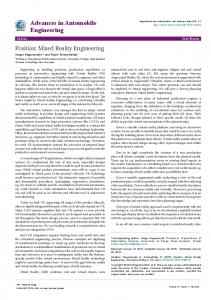
2.2 Projection Mapping Projection Mapping (PM) is a technique to project images or videos to surfaces of any kind of shapes, turning them into interactive displays [11]. Some of the simplest projections are made onto geometric shapes that can be flattened without stretching their surfaces [12]. Furthermore, factors such as geometry, image blending and warping, color and brightness uniformity, latency, and image retention must be considered when designing a high performance simulation using this technique [13] such as an assembly sequence simulation. PM technologies can be software-driven or camera-based systems that automatically align and blend with high accuracy. However, most of the software-driven solutions are programmed for flat screens using screen points for quick geometric calibration based on the authors’ experience. Furthermore, there is a large variety of tools (software and devices) which are useful for creating MR solutions using PM. Nevertheless, there is still a lack of integration and interoperability between them according to authors’ experimentations. In many cases, it is desired to interact with other external devices (e.g. external sensors for detecting workflows and context data), which requires specific implementation efforts tailored to the used software to achieve this integration. Available software solutions are often not designed for the specific needs of PM-based assembly assistance and come from different domains, requiring adaptations to make them usable for the mentioned use case of sequential assembly processes. Furthermore, most software solutions have either no external communication foreseen or provide only very simple communication interfaces, as for example VPT7, which includes socket-based communication for interacting with external devices. 3. A Mixed Reality Assistance System Development based on Project Mapping Technology The mixed reality assistance system proposed in this RTD work will provide virtual assistance to the operator by projecting instructions onto the workstation environment. The chosen set-up was a projector mounted in a fixed position over the assembly workstation. For benchmarking purposes, an existing case based also on AR technology was used as a reference [14]. In the benchmark case, Google Glass and Epson Glasse (BT-200) were used as the AR technology to display the instructions as a video-stream in their screen displays. The main advantage of the PM technique over the previous modality using smart-glasses is that there is no need for wearing any device, requiring a specific angle of view, and is integrated into the real environment. Furthermore, smart-glasses are currently limited by their computing power. The case of this RTD work refers to the manual assembly of a business card holder assembled in a poke-yoke, where the worker choses the correct parts and the proper tools for each step as following: Slide the clip in the glass piece, then put a distance plate and a steel piece on the glass piece, finally use a hammer and a chisel to apply pressure. Fig. 1 shows the difference between a traditional manual assembly and a manual assembly assisted by a mixed reality assistance system based on projection mapping technology for one exemplary process/instruction step.
Fig. 1. Traditional Manual Assembly vs. Assisted Manual Assembly ©SmartFactoryKL
For the proposed mixed reality assistance system, it was necessary to gain full knowledge of the business card holder assembly sequence and its surrounding environment, and to have a clear idea of the operational instructions for each assembly task to be assisted during the performance of the manual operations, so that the mentioned success factors for projection mapping of the assembly sequence be properly considered when mapping the working area and parts to be assembled.
4
Author name / Procedia Computer Science 00 (2015) 000–000
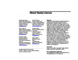
Furthermore, the modeling and rendering of the list of parts and tools involved in the manual assembly sequence of the business card holder, as well as the workstation (assembly module) as a 3D virtual world was made by a set of image computations of abstract and mathematical 3D-models describing the real world [15]. However any image of the parts and tools involved can be used for the projection instructions. Fig. 2 presents the existing assembly workstation at SmartFactoryKL that will be enhanced with the mixed-reality assistance system.
Fig. 2. Business Card Holder’s Manual Assembly Workstation ©SmartFactoryKL
3.1 Assisted Manual Assembly Sequence The manual assembly workstation is basically equipped with an assistance system and a recognition system [16]. The assistance system provides real-time instructions streaming from the Manufacturing Execution System (MES) on a screen in front of the operator. This assistance system was extended (augmented) by/with the projection mapping solution proposed, so that the instructions can now be visualized directly on the workplace and the operator be assisted in a natural way. While operations are performed, the workflow recognition system determines the actual work context, e.g. If the operation has been finished, the recognition system automatically displays the next instruction. Alternatively, the system can completely be controlled in a manual fashion way with a click. Step 1 – Take part instruction displayed: Take glass piece from the box. Step 2 – Assembly instruction displayed and highlighted by the projection mapping (where the part should be assembled): Place glass on the base with the groove facing up. Step 3 – Take part instruction displayed: Take clip from the box. Step 4 – Assembly instruction displayed and highlighted by the projection mapping (where the part should be assembled): Slide clip into the groove. Step 5 – Take part instruction displayed: Take the distance plate from the box. Step 6 – Assembly instruction displayed and highlighted by the projection mapping (where the part should be assembled): Put the distance plate on the glass piece. Step 7 – Take part instruction displayed: Take the steel piece from the box. Step 8 – Assembly instruction displayed and highlighted by the projection mapping (where the part should be assembled): Place the steel piece over the assembly. Step 9 – Take part and rotation instructions displayed: Take the assembly and rotate it 90 degrees and place it into the slot. Step 10 – Take tool instruction displayed: Take the hammer from the tools area. Step 11 – Take tool instruction displayed: Take the chisel piece from the tools area. Step 12 – Hammer instruction displayed and highlighted by the projection mapping (where the hammer should hit): Gently hit on the three small openings on the top of the assembly. Step 13 – Take part, rotation and placement instructions displayed: Rotate the assembly 180 degrees and place it into the slot.
Author name / Procedia Computer Science 00 (2015) 000–000
5
Step 16 – Hammer instruction displayed and highlighted by the projection mapping (where the hammer should hit): Gently hit the other side with the hammer. Step 18 – Put back the tools instruction displayed: Put back the hammer and the chisel into the tools area. “The Sequence was successfully completed”
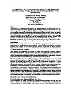
3.2 Operator Perspective In order to make the projection mapping instructions more realistic, it was required to implement a set of best practices for the proposed mixed reality assistance system: Perspective – The beamer was properly positioned so it can cover the required projection mapping area for each image (workstation, part, and tool). According to the operator’s angle/point of view, the image perspective view was adjusted. The 3D modelling and rendering was done with Autodesk 3DS MAX software. Meshing – In order to display an image in an irregular area, e.g. a groove. The image was divided into sections; each section was deformed to cover the different objects (parts and tools) in the workstation. Calibration – Once the image is meshed; the control points of the mesh are adjusted. Fig. 3 shows the sequence to create the image adjustment to the worker perspective angle.
Fig. 3. Meshing and Calibration Sequence
3.3 Software Solutions For the given environment of a manual assembly workstation, the following software solutions have been chosen: CAD software for 3D modeling of parts and tools e.g. to be shown in any sequence of any instruction to be followed by an operator – e.g. Autodesk 3DS MAX. PM software for projection environment calibration – e.g. Video Projection Tool (VPT7). A communication protocol to allow the interaction among computers and other multimedia devices, optimized for networking technology – e.g. Open Sound Control (OSC). 3.4 Hardware Solutions For the selection of the hardware components of a mixed reality assistance system, diverse hardware solutions can be chosen depending on the working area and the surface that should be covered by the projection mapping. For the given environment of a manual assembly workstation, the following hardware solutions were chosen: A laptop for 3D modeling and execution of a/the projection mapping solution. A projector and its mounting solution for covering the target projection mapping surface as well as to mount at the proper position and distance of the projector. A line of motion sensing input device for automatic detection of hands movement. 3.5 Automatic Detection/Recognition System The automatic detection of hands movement was implemented using a recognition system based on the Microsoft Kinect sensor motion controller. Fig. 4 depicts the workflow of the recognition system.
6
Author name / Procedia Computer Science 00 (2015) 000–000
Fig. 4. Recognition System Workflow
3.6 System Integration with Java Once the recognition system identifies the environment and movements, the next step is to use the information gathered by the Microsoft Kinect to integrate it to the assistance system. In other words, the running Java code determines when the operator successfully finished a step, so the assistance system can send a command for projecting the next step to the VPT through the OSC protocol (see Fig. 4). 3.7 Send Command Actions The communication between the workflow recognition system and the projection mapping solution chosen was VPT7, and it was realized with a socket-based communication. Since VPT7 is capable of different types of communication, including the Open Sound Control (OSC) protocol, the commands sent by the Java code were in the OSC protocol, e.g. /presetprev t 3.8 Instructions Operations (VPT7) For the meshing and calibration, in each step it is required to make a ‘preset’. A ‘preset’ is an array of layers and images that saves the correct deformation, so when the image is required; it is already adjusted for correct visualization. To display an image it is necessary to first Load the image, e.g. the clip, to the VPT7 and then assign it to a Layer. A Layer is a section area where the instructions are displayed; it can cover a small area or the entire surface; however the larger area, the more complex it will be, in this case, the layer of the clip. The layer is distorted with meshes to correct the image projection to adapt it to the workstation and assembly shapes as shown previously in Section 3.2. In Fig. 3 the system was developed as simply as possible, using only the three commands: /preset i /presetprev t /presetnext t 4. Limitations & Further Work A limitation of the proposed mixed reality assistance system is the reflectiveness on some materials, e.g. when projecting over a plastic transparent surface, the image quality decrease. The same occurs when projecting on surfaces at high degree field of view from the projector, a pixel stretching cause a poor quality image. The projection can be calibrated, but the quality is limited by the projection angle, the bigger the angle the worse the image. Also, the entire environment has to be manually calibrated, for each implementation its required knowledge of diverse software solutions involved. Also it still requires a lot of authoring effort. Further work improvements include using a calibrating system with depth sensors and integrating it to the mixed reality assistance system so it can track the environment, which means optically identifying real objects and making possible layers auto-calibration. A recommend device is the Microsoft Kinect, because it already includes many sensors for depth and color as well as a microphone array and is Microsoft Windows friendly.
Author name / Procedia Computer Science 00 (2015) 000–000
7
Another interesting system upgrade can be to make use of a multi-projector array to increase area coverage and therefore reduce image distortions on the surface or specific angles. 5. Conclusions In this paper authors presented the development of a mixed reality assistance system based on projection mapping technology to assist manual operations at assembly workstations. The system was successfully able to provide information (instructional guidance) directly at the place of action. To use it, any operator has to choose the required assembly task and then the PM solution projects the instructions directly onto the workstation environment, which will guide the user step-by-step until the whole assembly sequence is completed successfully. In conclusion, the mixed reality assistance system makes possible to enhance a typical manufacturing execution system. Acknowledgements The authors would like to acknowledge the support of the Mexican National Council for Science and Technology (CONACYT) and of the colleagues Nestor Ordaz and Harish Chakravarthy, as well as to the SmartFactoryKL – A Manufacturer-Independent Demonstration and Research Plat-Form – for the access to its facilities. References 1. Leu, M.C.; Elmaraghy, H.A.; Nee, A.Y.C.; Ong, S.K.; Lanzetta, M.; Putz, M.; Zhu, W.; Bernard, A. (2013). “CAD Model based Virtual Assembly Simulation, Planning and Training”. CIRP Annals - Manufacturing Technology, 62, 799-822. DOI: 10.1016/j.cirp.2013.05.005 2. Romero, D.; Noran, O.; Stahre, J.; Bernus, P and Fast-Berglund, Å (2015). “Towards a Human-Centred Reference Architecture for Next Generation Balanced Automation Systems: Human-Automation Symbiosis”. Innovative Production Management towards Sustainable Growth, Service, Manufacturing, and Resilient Value Chain, S. Umeda et al. (Eds.), IFIP, Part II, AICT 460, Springer, pp. 556-566, DOI: 10.1007/978-3-319-22759-7_64 3. Gorecky, D.; Schmitt, M.; Loskyll, M.; Zühlke, D. (2014). “Human-Machine-Interaction in the Industry 4.0 Era”. Conference Proceedings of 12th IEEE International Conference on Industrial Informatics (INDIN), pp. 289-294, 27-30 July, Porto Alegre, Brazil. 4. Vignais, N.; Miezal, M.; Bleser, B.; Mura, K.; Gorecky, D.; Marin, F. (2012). “Innovative System for Real-Time Ergonomic Feedback in Industrial Manufacturing”. Applied Ergonomics, 44, 566-574, DOI: 10.1016/j.apergo.2012.11.008 5. Gorecky, D.; Khamis, M.; Mura, K. (2015). “Introduction and Establishment of Virtual Training in the Factory of the Future”. International Journal of Computer Integrated Manufacturing. Taylor & Francis. DOI: 10.1080/0951192X.2015.1067918 6. Mujber, T.; Szecsi, T.; Hashmi, M. (2004). “Virtual Reality Applications in Manufacturing Process Simulation”. Journal of Materials Processing Technology, 155-156, Proceedings of the International Conference on Advances in Materials and Processing Technologies: Part II, 1834-1838. DOI: 10.1016/j.jmatprotec.2004.04.401 7. Jou, M.; Wang, J.; (2013). “Investigation of Effects of Virtual Reality Environments on Learning Performance of Technical Skills”. Computers in Human Behavior, 29, Advanced Human-Computer Interaction, 433-438. DOI: 10.1016/j.chb.2012.04.020 8. Behringer, R.; Klinker, G.; Mizell, D. (1999). “Augmented Reality: Placing Artificial Objects in Real Scenes”. Taylor & Francis, ISBN: 1-56881-098-9 9. Sandgren, J. (2011). “The Augmented Eye of the Beholder”, BrandTech News. 10. Florins, M.; Trevisan, D.; Vanderdonckt, J. (2004). “The Continuity Property in Mixed Reality and Multiplatform Systems: a Comparative Study”. Proceedings of 4th International Conference on Computer-Aided, Conference: Computer-Aided Design of User Interfaces IV, 323-334, DOI: 10.1007/1-4020-3304-4_26 11. PMC http://projection-mapping.org 12. Kennedy, M. (2004). “Understanding Map Projections”. Environmental Systems Research Institute. 13. Paul, L. (2008). “High Speed Simulation Solutions: Christie Total View Integrated Solutions”. Christie Digital Systems, IMAGE 2008 Conference. 14. http://www.smartfactory.de/ - A Manufacturer-Independent Demonstration and Research Plat-Form. 15. Rohlf, J.; Helman, J. (1994). “IRIS Performer: A High Performance Multiprocessing Toolkit for Real-time 3D Graphics”. SIGGRAPH Annual Conference on Computer Graphics, 381-394. ISBN: 0-89791-667-0. DOI: 10.1145/192161.192262. 16. Gorecky, D.; Campos, R.; Chakravarthy, H.; Dabelow, R.; Schlick, J.; Zühlke, D. (2013). “Mastering Mass Customization – A Concept for Advanced, Human-Centered Assembly”. Assembly Manufacturing Engineering Journal, 11(2), p. 62.