Developing Intelligent Environments A development tool chain for creation, testing and simulation of smart and intelligent environments Luis Roalter, Andreas M¨oller, Stefan Diewald and Matthias Kranz Technische Universit¨at M¨unchen Lehrstuhl f¨ur Medientechnik Arcisstrasse 21, 80333 Munich
[email protected],
[email protected],
[email protected] and
[email protected]
Abstract—Advances in the fields of distributed computing, wireless sensor networks, ubiquitous computing and many more have facilitated the development of a plenitude of Intelligent Environments (IE). The development processes, underlying tools and methods have however not yet been in the focus of researchers. A significant amount of time has to be spent for building a novel ecology of distributed systems to form an Intelligent Environment to conduct novel research in. A sophisticated middleware can shift the focus from building to research. Yet, a middleware is only one of the many requirements for leveraging the development process of Intelligent Environments. In this paper, we present a complete tool chain to simplify research on Intelligent Environments and to ease their creation. This tool chain consists out of middleware, simulation, visualization and prototyping tools. We start by modeling the physical environment using a CAD software and visualization tool including physical properties. The tool chain is complemented by a middleware and a sophisticated simulation environment allowing e.g. to simulate mobile phone interactions triggering, and the deployment to the real-world events. For developers and researchers of Intelligent Environments, creation and maintenance of Intelligent Environments is significantly improved. Development is speeded up as algorithms, interaction can be already evaluated and tested in simulation before the deployment to the real world. Index Terms—Development Process, Smart Spaces, Intelligent Environments, Mobile Devices, Android, ROS, Development, Middleware
I. I NTRODUCTION The engineering of Intelligent Environments (IEs) is still a challenging and time consuming task. The construction, from prototyping to building, already poses high demands on the researcher. After several years of research, several middleware options for ubiquitous computing have been proposed to facilitate the interconnection of heterogeneous devices via various types of networks. The overall reuse of middleware solutions in the domain of ubiquitous computing, though, is very limited. Additional challenges are faced when visualization of the current state of the various systems are of interest. Nearly no solutions for the researcher are available when it comes to the simulation of Intelligent Environments in the sense of data or event creation or the simulation of interaction. However, these features would allow to increase the development speed, enabling e.g. to parallelize the development of the actual environment and the development of algorithms and services. As of now, the environment has to be prototyped and constructed, then data are collected, algorithm development
is started and eventually applications are built on top. This process is very time-consuming, and the focus is mainly on the various engineering activities instead of research activities. A respective comprising tool chain has so far not been reported. We will fill this gap to allow researchers to shift their efforts more on the research and application development phases. Intelligent Environments are heterogeneous distributed sensor-actuator systems including multimedia presentation services, building automation and control components, intelligent physical objects, wireless sensor network nodes, nomadic personal or shared devices, and many other systems and entities. This complex setup demands for leveraged support on each of the following tasks: prototyping and development, system state visualization and environmental simulation of all potential components, along with their physical and digital properties. We will present how our proposed tool chain, consisting of a new combination of existing tools and new developments, will leverage all three aspects. A prerequisite for the desired support is a middleware that allows for connecting of all these heterogeneous distributed components, either directly by respective open source or proprietary drivers or via e.g. proxy sockets. They will be connected directly to a e.g. room-central master server or to decentralized nodes that are in a peer-to-peer fashion are interconnected via different network types and topologies to the central management unit. This main component will later be referred to as (ROS) master core, the distributed systems as (ROS) nodes. The objects of interest, such as sensors, sensor systems, actuators, physical smart objects, etc. are called entities for the remainder of this paper. The paper is structured as follows. After the discussion of related work with a focus on middleware and the engineering of ubiquitous computing environments in Sec. II, we will present a high-level view on the proposed tool chain, introducing the individual components in Sec. III. We will give an example of an intelligent environment constructed following the proposed approach in Sec. IV. We will explain in detail what strength and properties of the composed tools allowed us to speed up and facilitate the overall development process. This example will include a mobile personal device, an Androidbased smartphone. We will conclude with an outlook on future improvements of the development tools and the engineering processes, e.g. an end-user programming front end for complex Intelligent Environments.
II. R ELATED W ORK The construction of an Intelligent Environment is not an easy task, nor is it ever ‘complete’: devices, systems and applications will be added and removed, potentially during runtime, the configurations may be subject to change e.g. when nomadic devices which often are used as proxies for the presence of users ,such as smartphones, enter and leave, or devices eventually fail due to connectivity problems, battery drainage or many other potential reasons. The glue between actual virtual or physical devices and the application is the middleware. It has a variety of functions, such as hiding the complexity of implementation or hardware details, abstracting from devices and interfaces, etc. In the context of ubiquitous computing, specialized middleware have been proposed. e.g. for context-aware applications, such as Aura, GAIA and others (see [1] for a survey). Other middleware focus on security, such as FAME-PERMIS, SMMU and others (see [2] for a survey). or on a service-oriented approach (see [3] for a survey). There exist many other general-purpose middleware systems (see [4] of a survey) using many different data exchange and propagation mechanisms, from publish/subscribe, service-oriented and eventbased architectures requiring or not requiring central databases of available components and services. A great number of protocols, technologies and approaches has been proposed, such as DCOM, CORBA, SOAP, web services, etc. Yet, none has been accepted by the community as de-facto standard middleware for Intelligent Environments. Reasons are, amongst others, limited driver and device support, lack of a significant number of community supporters, flexibility to the middleware to be employed in a larger number of scenarios, etc. We believe that both the lack of a commonly agreed upon middleware in conjunction with limited development support is one of the large problems in this research community. Lacking the underlying tools, we are not able to continue research on things such as development and design patterns for intelligent environments an ubiquitous computing [5] or on software and systems engineering methodologies. Middleware for Intelligent Environments like GAIA [6], Mundocore [7] or RCSM [8] do only represent the states, connections and transition between sensors and actuators. The actual implementation of the connection between the sensors does not play a big role any more. Simulation, physics and space are usually not represented to a degree to e.g. include aspects of interaction, accessibility or motion for or with humans or robots. We argue that that a digital representation is not enough for a meaningful middleware for current demands towards Intelligent Environments, but additionally 3D simulation is necessary. In the AwareHome [9] or MIT’s House n [10], the researchers have constant and reproducible conditions and tried to maintain them. Additionally, no or only little nomadic devices were included. The physical settings were fixed, a transfer of lessons learnt to a new environment or other scenario is somewhat questionable. Also, few recent papers report
on novel large-scale intelligent environments to have been built. Linner et al [11] recently researches on environments for ambient assisted living (AAL) scenarios to build up a sub environmental concept. Such environments should include a pre-configurable middleware which needs to communicate with the infrastructure (like modules that are connected to computer barebone to extend the functionality in the digital sense and a physical room-in-room add-on concept for the real world). Such prototypes are very expensive and are evaluated best with many conditions in a short time. We will in the following chapter discuss how we include simulation software such as Gazebo [12] on top of a middleware (called ROS, robot operating system) for distributed sensor-actuatorsystems, namely robots, for simulation and data exchange purposes. Extensions made by us include e.g. a CAD software that exports 3D drawings of buildings and furniture as ”immobile robots” [13] to both the visualization and simulation subsystems, extensions of the middleware to run on Androidbased smartphones, and others. Similar approaches have been reported by e.g. Kranz et al. [14], [15], while they have been using Player/Stage [16] as middleware. Their results are comparable in that they also have been exploring the potentials of robotic middleware systems for intelligent environments and ubiquitous computing. Their approaches though did not include 3D modeling or mobile phones and the simulation of mobiles. A more recent approach of Roalter et al. [17] pursued a similar approach, but focused on a componentoriented approach, e.g. how to build an environment in the AAL context, using an ”IKEA” shelf-only approach. Neither robots, humans or interaction has been included which inspired us to investigate the potential of ROS on which we report in the remainder of this paper. III. D EVELOPMENT AND T OOL C HAIN We present our toolkit and discuss about the tools contributing to the creation of an intelligent environment. We begin with the middleware, describe the physical simulation of the environment to create, and conclude with the creation of a 3D simulation. To get started with the tool chain we need to define some requirements. The middleware is developed using automated dependency resolution on Ubuntu Linux, every other tool or program used during research should be able to compile or at least run on a Linux machine. A. Middleware Starting with a distributed sensor and actuator environment, we need a middleware which can communicate with all these sensors and actuators. We do not want to create a new middleware on our own, but are using a middleware which is already existing and working. We found the middleware ROS (Robot Operating System) [18] to fit best for our purposes. Using ROS provides several advantages: ∙ Reduction of the amount of time being spent for implementing abstract and basic communication methods ∙ Avoidance of the adaption of the middleware from a specific problem to our research
the same middleware providing the same interfaces for all components.
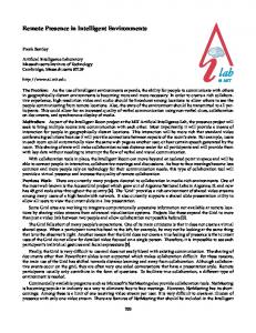
Fig. 1: Both real and simulated environment can work interweaved together. On the left side we present the real system, with real sensors, actuators and visualization devices. On the right side, there is the same representation as for the simulated environment, including recording and replaying of sensor/actuator values. In the middle there is the middleware ROS where code and algorithms are run for both systems.
Profit from a large community improving drivers and middleware ∙ Compatibility of the middleware with a large pool of hardware systems Further characteristics of the usage of ROS as middleware can be found in [19]. ROS is originally written for the robotics domain. Most entities in an environment can be seen as a nomadic mobile or immobile robot. The middleware plays an important role for making interactions possible. In the base configuration there is already included support for ∙ Different data exchange mechanisms (publish/subscribe and call-response services) ∙ A great variety of different hardware systems ∙ Simulation ∙ Different programming languages ∙ Peer-To-Peer architecture The possibilities for developing drivers with ROS for different platforms on one simulation platform makes it possible to port an application to support nearly every target hardware system. Our extension to the middleware is in defining a clear procedure how a communication between sensors should be implemented according for a home automated environment. Mobile robots do not differ from immobile robots. You can define nearly every entity of an environment as an mobile or immobile robot providing sensor and controlling values to the middleware. As shown in Fig. 2 both robots and environment can exchange information. This task is simplified by having ∙
Fig. 2: This figure shows a comparison between a well-known mobile robot and an intelligent environment consisting of distributed sensor-actuator systems. In the filled black boxes there runs a middleware – in our case the same middleware. You can see the connection in the middle both systems are able to communicate with each other. An entity like a surveillance camera could be accessed as immobile but controllable robot feeding its camera stream into the environment making smart decisions for other tasks. This system would be useful in surveillance or locating systems where mobile and immobile robots should work together. In the middleware each component – called node – can provide a variable amount of services or feeds. Distributed systems can subscribe to feeds of other systems. In our environment sensors will provide the middleware with status messages or controlling services. Each information feed which can be subscribed or published is called a topic. Currently concurrent running services providing the same service will overlay each other. There is no need for a topic to be announced continuously, the nodes can be easily exchanged providing less, the same or more topics to the environment. This makes it even possible for different versions with differing interfaces to connect to the system. B. Physical Simulation – Gazebo Every entity comes with physical representation. Only visual simulation of the surface is nice for a presentation, but does not express anything about the possibilities of interaction between them if they would be placed in the real environment. The middleware brings for this problem a visual simulation system called Gazebo. Gazebo is not part of a the middleware itself, however plug-ins for Gazebo build up a connection between the middleware and the physical model. These plugins can model physical properties for actuators like force or impulse. Most properties are already part of Gazebo and can be used out of the box.
Fig. 3: This Figure demonstrates the concept of real and simulated hardware shown to an application. The application uses an abstract hardware interface which can be filled with information from either the real hardware, simulated or recorded hardware. The bag is just a container of datastreams from different data sources. Now, each visual entity in the environment needs to be described in a way Gazebo will recognize it. For describing them we need to make use of a XML language called URDF. This Unified Robot Description Format contains information about ∙ Visual Representation – which is about geometry, color and textures ∙ Inertia / Mass – properties like mass or resistance to force ∙ Collision Matrix – specifying the bounding boxes of an object to avoid collisions with other objects These shapes are connected to each others and can be manipulated with Joints. For environment simulation purposes a rotating joint could be a hinge-joint of a door. The main difference between robots and environments is that a joint for a robot will represent an actuator or a motor which can be controlled in a real situation. For an environment this is not always the case. The connections between different shapes can be controlled with the joint itself. To do so you need to distinguish between ∙ fixed joints, e.g. for walls ∙ revolute or continuous joints, e.g. for a door or a window ∙ prismatic joints, e.g. for a drawer ∙ floating joints, e.g. for free movable stuff ∙ planar joints, e.g. for moving stuff on a surface All of these joints and connections represent a physical connection between the two parts. For manipulation there are two ways for doing it. First you could just override the state of the joint, moving a part from one maximum to another maximum. The better way is to smoothly move a connected item from state A to state B. C. Sweethome 3D – a CAD software for designing homes In the actuator prototyping process it is quite complicated to understand which objects are to connect. For a complex and
Fig. 4: The graphical user interface of SweetHome3D, a open-source modeling tool written in Java. We enhanced the program by including ROS and Gazebo specific fields in the furniture elements. This makes it possible to specify controllers, actuators and sensors in an environment without editing XML source code.
reusable robot the creation of the model can be done once and improved over the research cycle. In an environment it needs to be easily placed wherever the researcher wants an object to be placed. Moreover the common research won’t learn to write XML files. Architects or designers want to have a toolkit, where they can browse an existing pool of objects. This is mostly the case when dealing with designing an interior of an environment. The middleware ROS and the URDF language were initially not conceived to model whole environments. For that reason, a solution had to be found to build an environment out of individual pieces, and to automate this workflow, to avoid the need of repeatedly recreating entities. For shapes there is already a possibility to import Collada models [20]. This 3D model file can be already parsed in parts by Gazebo. But the physical connection and layout cannot done without a designing software at all. For this reason we followed the path of using an adapted version of a designing software called Sweethome 3D [21]. In this software the user can build complex environment our of a library of shapes and predefined forms (See Fig. 4). We used the original software and extended it for the usage with our simulation environment. Therefore, additional properties had to be defined for each entity, such as ∙ Shape ∙ Color ∙ Weight ∙ Inertia ∙ Parents the entity belongs to ∙ Relation to the parent (dynamic, fixed) When all these properties are specified for an environment, the entire model (or individual parts needed) can be exported
and the simulated environment. The middleware will react as the system will react when it is built. Every entity in the environment will now be seen as a intelligent part of an distributed computing network. Each such an instance works like an input/output system as presented in Figure 8. We will create an example modeling here to implement an intelligent room controller. A. Creating the room and nodes
Fig. 5: On the top you can see an example environment modeled in Sweethome3D. The separation between dynamic – movable parts – and fixed parts is already done. On the bottom side the model was loaded into the simulator software Gazebo. The textures are still missing but you can recognize the shapes transfer from Sweethome to Gazebo.
We have already created a room in Fig. 5. In this room we will add now an intelligent controller, which can switch on or off the light manually or trough an intelligent algorithm. We will include a smartphone to interact with the middleware, even using the same networking libraries as the middleware. Dynamic actuator parts will be ∙ Doors ∙ Chairs ∙ Windows ∙ Lights These objects are already exported from SweetHome3D to the Gazebo simulator. The just specified objects are connected to the fixed elements with a joint – except the light source which needs to be inserted and removed from the model on demand. The scenario will be to sense the environment light and temperature and adapt the environment according the preferences of the user. We will have sensors for ∙ Temperature ∙ Motion detection ∙ Light ∙ Reed Contacts (Windows, Doors) The sensor and actuators need to go through their controlling routines. These programs are part of the middleware
as independent URDF model files. The resulting model can then be loaded into the simulation environment (see Fig. 5). The next step is then to connect them to the controlling or monitoring driver in the middleware. IV. A N E XAMPLE E NVIRONMENT We now continue the workflow with the concrete example of an environment that has been created in the above described way. The room can be seen in Figure 5. The exported SweetHome3D model is converted into a set of robotic model files. Each model file contains one specific object. The properties of the object are specified to its real physical parameters as shown in Figure 6. To avoid a too high number of files, we combine all immobile parts to one model, such as e.g. floors or walls. The dynamic parts can now be spawned (integrated into the simulation) as necessary. Before we start to move parts in the simulation, we will start again from the top as we have described in Figure 1. At that point the interface to the real sensors and actuators needs to be defined. Real models or hardware solutions should be tested before they are ordered. In our case you can already start with the algorithms and drivers using the middleware
Fig. 6: In the designing software you can specify common parameters: Physical properties are important for the simulation and visualization. For still there are only a few options available. But it can distinguish between fixed and movable parts by appending movable to the URDF name descriptor
gravity and forces apply entities cannot go through walls ∙ entities can be moved, rotated, removed or added, just like real-world objects ∙ entities collide with each other when they touch, enabling the simulation of complex object interaction If e.g. a door needs to be drawn open, the door will only open if it is physically possible. If there is a robot located right behind the door, the door will touch the robot and won’t open more. You can override this behavior, but you probably want your middleware to avoid collision errors even in the simulation. In our example the doors and windows will only open completely if there is nothing around them. If they would be overridden in the simulation a smart environment would not take care about such situations either. We want to help even humans and robots to interact with the environment. So it makes sense to detect and visualize such problems. ∙ ∙
Fig. 7: Every component and every object is related with another object. This figure depicts how SweetHome organizes the objects to be placed into the simulation Gazebo.
Fig. 8: An entity – which can be either a sensor, an actuator or anything else – can get information from its real sensors, but can also be overridden in simulation by exchanging the module communicating with the Abstract Interface.
programming. For every sensor or actuator you probably need to create a separate node. You can combine equal tasks to one node, thereby avoiding too many programs being created for an environment. The nodes can now generate commands to control the real environment connecting the hardware interface. The interface can now be connected to the real hardware or just the simulated hardware. The system will act identical in both cases. B. Physical Force Simulation In the real world you can easily include an actuator by connecting its pins to the output. In the simulation, it is not that easy to simulate physical properties and forces. Gazebo already has the capability to calculate physical properties for robots. We make use of these built-in functionality by specifying the weight, size and inertia of our objects. We mentioned earlier that we cannot manipulate the Gazebo model directly. On this part additional implementation efforts are necessary. However, a thorough work in this part results in an accurate simulation of a real environment with all of its objects and related physical properties included. This comprises e.g. that
Fig. 9: The simulation is just a visualization of the environment. Even if the visualization – using Gazebo or RViz – fails, the environment will still work without any limitations.
C. Discrete Controlling Opening or closing the door just like switching the light on or off is a binary task. This discrete controlling is a common behavior in smart environments. To avoid problems with discrete states, you always need to switch between states smoothly, or, to let it appear discrete, in a very fast way. To go further in our example we will connect now the joints of the windows and doors to our driver. The driver senses whether the doors or windows are open or closed and will propagate this to gazebo over the plug-in. The simulation will now try to visualize the state door open in the simulation. The driver knows the two states of the door – open or closed – and tries to transit the state from open to closed. For the door the rotating joint will be accelerated and the entity connected to the joint will start to move. A door is very interesting in a simulation. Doors are the connection between rooms. Robots, objects or humans need to use them to get from one room to another. As Fig. 7 illustrates, every room is connected to another room also in the model. Even if it is very interesting to simulate, in the real
environment overriding the state of a door won’t be propagated at all currently. Here human beings and robots are in danger if the door opens due to a simulation fault. On the other hand the recording and replaying of the state change can be very useful on surveillance tracking or just on simulating one task again and again. D. Implementation and Testing The visualization can be the first step to gather results for research, before any real-world deployment. Now we can eventually focus on the generation, propagation and usage of sensor values and corresponding actuator events, without caring of an implementation of a real environment. We will assume from now that all dynamic components of the simulator are connected to the outside over a specific driver. As we started we discussed having a temperature and light sensor in the environment. These sensors can be connected to some distributed computing system and send their information collected from real hardware sensors or grabbed from online forecasts. As described in the section above, you can record these sensor values for creating stabilized and controlled environmental conditions. These values can also be generated by hand and replayed to the system as if they were currently measured. The development and testing of algorithms e.g. for environmental head or light controlling usually requires numerous test runs under stable conditions, i.e. with the same controlled input values. This intensive process of collecting and replaying information for such sensors can be performed very comfortable with such a simulation in an automated way, without doing the tasks in real or simulation again and again. The sensor values are processed in the exact same manner, no matter whether they are simulated or real. You can work on the same research topic with original values all over the world without having to buy the real hardware for every place. In
Fig. 10: An easy controller for the environment. You can generate sensor values by clicking on the button. If the simulation shows up the result, so will the real environment if an actuator is connected for the task. the best case you would be able to simulate the general tasks with an interface containing buttons for your task (see Fig. 10). The sensor values can now be included into a algorithm which could take care about the plant in the room e.g. switching on an UV-lamp or cooling the room. E. Mobile Interaction using Smartphones The presented environment and tools allow the simulation and testing of complex software systems, which is illustrated by an example scenario we created for mobile interaction.
A state-of-the-art smartphone includes various sensors and actuators. Extending standard wireless sensor nodes enables an environment to benefit from a multi-medial device, which makes possible a variety of scenarios. The environment could make use of e.g. ∙ Positioning Sensors (GPS, GSM cells, WLan, ...) ∙ Wireless Networks ∙ Light Sensors ∙ Camera ∙ Display Device ∙ Touch Screen ∙ Microphone and Speaker As proof-of-concept demo, we use a smartphone as ‘remote control’ to switch on and off the lights in our intelligent environment. We implemented a GUI on the smart-phone with JQuery Mobile [22] (see Figure 11), able to run both in a webbrowser and on a mobile device. Sending the light switching commands to the virtual hardware, affects both the actuators in the simulation and the real environment.
Fig. 11: A control user interface on a Android smart-phone using JQuery mobile. In this simple application you can select a room and show the light state in there. You can also manipulate the light state by switching lights on or off. This demo is implemented by running a complete middleware core on the mobile phone, communicating with the server. Any process within the middleware will be able to connect to the device from every location. This illustrates the flexibility of the ROS middleware and gives an outlook to potential future scenarios and applications. V. C ONCLUSIONS AND F UTURE W ORK The rapid prototyping of environments is becoming more and more important in research. The time from idea to implementation and research can be reduced by using a tool chain as proposed. One of the main and still unsolved problems for researchers in the domain of Intelligent Environments is a suitable middleware. We have shown that the proposed systems and tools, with the presented extensions and novelties, are suitable to allow for a significant reduction in efforts and complexity, while maintaining a high degree of flexibility and possibilities for reuse. In our future work we plan to pursue two main lines: on the one hand, we will, as now tools are available, focus on
Fig. 12: The available time for actual research will increase through using our system. While in conventional research, concepts often have to be reimplemented partly or entirely new, our proposed tool chain allows recycling significant parts of modeling, simulation and prototyping efforts, and using the saved time for the development of new ideas and research approaches.
the development of methodologies and patterns, as they are already available and well accepted in e.g. standard software engineering. On the other hand, we will complement the presented development chain with additional features and tools. A possible extension could be a comfortable environment for end users to program their own application and context-aware behavior on top of the middleware – with real time testing in the 3D simulation. This will significantly leverage the supported complexity of context-aware systems as indicated in Fig. 12 – current tools such as the Context Toolkit [23] allow only for simple, rather rule-based end user programming without standardized graphical simulation. Future research will also be directed towards the simulation of humans (as ‘robots’) to allow the investigation of interaction-related questions. ACKNOWLEDGMENTS This work has been partially funded from the German DFG funded Cluster of Excellence ’CoTeSys – Cognition for Technical Systems’ and the BMBF funded AAL project ’GewoS – Gesund wohnen mit Stil’. R EFERENCES [1] K. E. Kjaer, “A survey of context-aware middleware,” in Proceedings of the 25th conference on IASTED International Multi-Conference:Software Engineering. Anaheim, CA, USA: ACTA Press, 2007, pp. 148–155. [Online]. Available: http://portal.acm.org/citation.cfm?id=1332044.1332069 [2] J. Al-Jaroodi, A. Al-Dhaheri, F. Al-Abdouli, and N. Mohamed, “A survey of security middleware for pervasive and ubiquitous systems,” in Network-Based Information Systems, 2009. NBIS ’09. International Conference on, Aug 2009, pp. 188 –193. [3] N. Ibrahim and F. L. Mouel, “A survey on service composition middleware in pervasive environments,” August 2009. [Online]. Available: http://cogprints.org/6684/ [4] N. Ibrahim, F. Le Mou¨el, and S. Fr´enot, Middleware Technologies for Ubiquitous Computing, ser. Handbook of Research on Next Generation Networks and Ubiquitous Computing. IGI Global Publication, 2010, chapter 12, pp. 122–131. [5] J. A. Landay and G. Borriello, “Design patterns for ubiquitous computing,” Computer, vol. 36, no. 8, pp. 93–95, 2003.
[6] M. Rom´an, C. Hess, R. Cerqueira, A. Ranganathan, R. H. Campbell, and K. Nahrstedt, “A middleware infrastructure for active spaces,” IEEE Pervasive Computing, vol. 1, no. 4, pp. 74–83, 2002. [7] E. Aitenbichler, J. Kangasharju, and M. M¨uhlh¨auser, “Mundocore: A light-weight infrastructure for pervasive computing,” Pervasive Mob. Comput., vol. 3, no. 4, pp. 332–361, 2007. [8] S. S. Yau, F. Karim, Y. Wang, B. Wang, and S. K. S. Gupta, “Reconfigurable context-sensitive middleware for pervasive computing,” IEEE Pervasive Computing, vol. 1, no. 3, pp. 33–40, 2002. [9] C. Kidd, R. Orr, G. Abowd, C. Atkeson, I. Essa, B. MacIntyre, E. Mynatt, T. Starner, and W. Newstetter, “The aware home: A living laboratory for ubiquitous computing research,” Cooperative Buildings. Integrating Information, Organizations and Architecture, pp. 191–198, 1999. [10] S. S. Intille, K. Larson, E. M. Tapia, J. Beaudin, P. Kaushik, J. Nawyn, and R. Rockinson, “Using a live-in laboratory for ubiquitous computing research,” in Pervasive, 2006, pp. 349–365. [11] T. Linner, M. Kranz, L. Roalter, and T. Bock, “Compacted and industrially customizable ambient intelligent service units: Typology, examples and performance,” in 2010 Sixth International Conference on Intelligent Environments, Kuala Lumpur, Malaysia, 2010, pp. 295–300. [12] N. Koenig and A. Howard, “Design and use paradigms for gazebo, an open-source multi-robot simulator,” in Intelligent Robots and Systems, 2004.(IROS 2004). Proceedings. 2004 IEEE/RSJ International Conference on, vol. 3. IEEE, 2005, pp. 2149–2154. [13] R. P. Goldman and C. Baral, “Robots, softbots, immobots: The 1997 aaai workshop on theories of action, planning and control,” Knowl. Eng. Rev., vol. 13, no. 2, pp. 179–184, 1998. [14] M. Kranz, R. Rusu, A. Maldonado, M. Beetz, and A. Schmidt, “A Player/Stage System for Context-Aware Intelligent Environments,” in Proceedings of the System Support for Ubiquitous Computing Workshop at UbiComp, 2006. [15] M. Kranz, A. Schmidt, R. Rusu, A. Maldonado, M. Beetz, B. Hornler, and G. Rigoll, “Sensing technologies and the player-middleware for context-awareness in kitchen environments,” in Networked Sensing Systems, 2007. INSS ’07. Fourth International Conference on, June 2007, pp. 179–186. [16] T. H. Collett, B. A. MacDonald, and B. P. Gerkey, “Player 2.0: Toward a practical robot programming framework,” in Proc. of the Australasian Conf. on Robotics and Automation (ACRA), Sydney, Australia, 2005. [17] L. Roalter, M. Kranz, and A. M¨oller, “A middleware for intelligent environments and the internet of things,” in Ubiquitous Intelligence and Computing, ser. Lecture Notes in Computer Science, vol. 6406. Springer Berlin / Heidelberg, 2010, pp. 267–281. [18] M. Quigley, K. Conley, B. Gerkey, J. Faust, T. B. Foote, J. Leibs, R. Wheeler, and A. Y. Ng, “Ros: an open-source robot operating system,” in ICRA Workshop on Open Source Software, 2009. [19] M. Kranz, A. M¨oller, and L. Roalter, “Robots, objects, humans: Towards seamless interaction in intelligent environments,” in 1st International Conference on Pervasive and Embedded Computing and Communication Systems (PECCS 2011), Algarve, Portugal, 2011. [20] R. Arnaud and M. Barnes, COLLADA: sailing the gulf of 3D digital content creation. AK Peters, Ltd., 2006. [21] “Sweethome 3d,” http://http://www.sweethome3d.com/. [22] E. McCormick and K. De Volder, “JQuery: finding your way through tangled code,” in Companion to the 19th annual ACM SIGPLAN conference on Object-oriented programming systems, languages, and applications. ACM, 2004, pp. 9–10. [23] A. Dey and G. Abowd, “The context toolkit: Aiding the development of context-aware applications,” in Workshop on Software Engineering for wearable and pervasive computing. Citeseer, 2000, pp. 431–441.