Developing Interfaces For Collaborative Mobile Systems Keith Cheverst, Nigel Davies, Adrian Friday Distributed Multimedia Research Group, Department of Computing, Lancaster University, Lancaster, LA1 4YR. telephone: +44 (0)1524 65201 e-mail: kc,nigel,
[email protected]
ABSTRACT This paper describes the issues encountered when developing user interfaces for collaborative multimedia applications designed for operation in unreliable mobile networking environments. To provide end-users with some degree of dependability applications need to provide increased levels of user-awareness in order to enable users to adapt their style of interaction to match the current quality of communications. The application described in this paper achieves this by presenting users with graphical feedback when the constraints imposed by the network violate the collaborating groups’ various communications requirements. Because traditional distributed development platforms tend to mask detailed network information from reaching the application the development platform was enhanced to enable the flow of information between the network and application level services and vice versa.
1. Introduction Despite the well established research field of CSCW and the growing popularity of mobile computing technologies, relatively little research has examined the issues of developing collaborative mobile systems. This paper describes research carried out under the MOST project [MOST,95] which focused on developing mobile computing support for field engineers in the safety critical domain of the U.K. power distribution industry. MOST was a collaborative project involving a partnership between the Computing Department, Lancaster University and EA Technology Ltd, Capenhurst. The project ran from April 1993 to September 1995 and was funded jointly by EPSRC and the DTI. In order to support field engineers, MOST produced a prototype application which was arguably the first collaborative mobile application ever built that was capable of adaption in a heterogeneous environment [Cheverst,94]. To date, the project has provided the most complete study into the issues surrounding the development of collaborative mobile systems.
2. The MOST Application Domain In order to provide electricity to its consumers the power distribution industry has to manage a mass of complex cabling and each REC (regional electricity company) has to deal with managing the supply of 1
electricity to approximately 1.8 million electricity consumers. Problems with the power distribution arise quite frequently and when such problems occur and consumers are left without supply there is a strong financial incentive for the REC to return supply as soon as possible. Usually when a fault occurs on the network it is necessary to re-route supply via an alternative path, this is known as ‘switching’. Field engineers are required to physically perform switching operations at ‘Switching stations’. A control centre is responsible for coordinating the work of field engineers and for maintaining an up-to-date view of the network state. For reasons of safety, it is crucial that such a view be maintained and that no inconsistencies regarding the current network state exist. For example, the control centre needs to be certain that a section of network has been ‘earthed’ before instructing a field engineer to perform a repair on that section of network. In order to maintain the consistency of network views the control centre imposes a sequential ordering on all operations affecting the network.
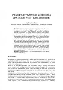
2.1 Typical Fault Scenario The type of cable fault that might occur in part of the LV (or Low Voltage) network is illustrated below in figure 1. Feed B (11kv)
Feed A (11kv)
Swiching Station 2
Feed C (Reserve 11kv) 11 kv
Steel Works Factory
Swiching Station 3
Ground
11 kv 11 kv
Housing Estate 11kv to 240v Transformer
Swiching Station 1 Cable Fault Ground
Figure 1: Typical cable fault scenario.
Prior to the cable fault the housing estate received supply from ‘Feed A’ and the factory received supply from ‘Feed B’. However when a cable fault occurs, as shown, then the housing estate suffers a complete loss of supply. The control centre is thus required to coordinate a switching operation to return supply to the housing estate. Once certain of the fault’s location, the control centre analyses the current view of the network in order to find a way of re-routing supply to the housing estate. The control centre decides to restore supply by utilising the factory’s reserve power feed and diverting power from the factory to the housing estate. To achieve this re-routing of supply requires field engineers to perform switching operations at switching stations ‘3’ and ‘2’ respectively. The ordering of these two operations needs to be guaranteed by the control centre in order to prevent the factory being without supply. The control centre is able to ensure that the correct ordering is achieved by imposing a sequential ordering on all operations affecting the network. A switching operation should also be performed at switching station ‘1’ in order to make the damaged cable safe for later repair work.
2.2 Requirements of the Power Distribution Industry MOST conducted an extensive requirements capture exercise, which involved members of the project team conducting individual interviews with various members of the power distribution industry. This exercise identified the following set of requirements :The Need for Integration between Utilities Companies The power distribution industry, in common with all utilities industries, deals with geographic based information such as cable or road networks. Currently, there is little sharing of such information between 2
the various utilities industries and as a result unnecessary interference between them occurs on a regular basis. A common example of this interference is the accidental fracturing of one companies’ cable or pipe by another company laying some new cable of their own. In order to allow a greater level of integration and interoperability between the various utilities industries some form of common or open standards needs to be devised. Hopefully, this could result in a situation whereby a unified, constantly updated, network diagram becomes available to all utilities companies. This would enable extremely useful inter-utility collaboration and cooperation resulting in significant gains in safety and efficiency across the utility industries. For example, if one utility company planned to perform extensive cable maintenance on a particular street then this information could be shared by illustrating the plans on a unified network diagram. If another utility company had scheduled work on that street then one would hope that the two utilities would cooperate to the extent that the street would only be dug up once, thus reducing disruption and the cost to the utilities companies involved. An attempt at producing such a unified network diagram is currently in development in the form of the Common Street Works Register (CSWR). The Need for Decentralisation of the Work Load The power distribution industry currently operates a centralised control structure in which all operations are coordinated and serialised by the control centre. This structure has the inherent problem that during periods of intensive activity, e.g. during an electrical storm, the control centre can become a system bottleneck. This situation is clearly not acceptable, and a less centralised control structure needs to be put in place. Ideally, this would be achieved by distributing (i.e. replicating) the current network view amongst all concerned, rather than permitting the control centre to hoard the current view. There are obviously strong implications for maintaining consistency where multiple copies of the current network view exist. These implications are made all the more dramatic when one considers the unreliable communications infrastructure available for sending updates between the control centre and mobile field engineers. The Need to Improve the Distribution of Information to Field Engineers One function of the control centre is to act as a central repository of information such as composite mains records and network schematics. The problem with this approach is that whenever a field engineer requires such information he or she needs to visit the control centre in order to collect the relevant paperwork. The maintenance field engineer is also required to visit the control centre in order to receive their latest job instructions and to query any one of the companies database systems. Substantial improvements in efficiency could be made by simply enabling the field engineer to access this information whilst out in the field. This could be achieved by providing the field engineer with an appropriately equipped portable computer i.e. one containing a CD-ROM to store largely static information and a modem for receiving dynamic updates and for enabling remote database access . The Need for Improved Collaboration Currently field engineers are provided with little support for collaborating with one another and with members of the control centre. Gains in operational efficiency could be achieved by enabling field engineers to reliably share information and ideas between one another. Many of the problems encountered with verbal communication, such as ambiguities, could be solved by providing field engineers with tools enabling them to exchange and share multimedia information such as text, graphics and sound in a structured way. For example, given the ability to share graphical information, an engineer could demonstrate to other engineers exactly where on a network diagram he or she suspected there to be a fault.
3
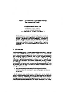
3. Characteristics of Mobile Computing Environments Mobile computing environments inherit the associated problems of both heterogeneous processing and heterogeneous networking. The heterogeneous processing element of mobile computing environments involves the need to manage relatively low-power mobile hosts including PDAs, handheld PCs and notebook PCs. Such mobile hosts also tend to have limited resolution displays and a variety of different operating systems e.g. NewtonOS and WindowsCE. The heterogeneous networking element arises from the need to utilise different networking technologies in order to maintain network connectivity whilst mobile. For example, mobile computers can be either disconnected, weakly connected by low speed wireless networks such as GSM, or fully connected by high speed networks ranging from Ethernet to ATM. Figure 2, below, demonstrates the range of connectivity available in a mobile environment and illustrates the basic trade-off between the freedom of movement and available bandwidth offered by a range of networking infrastructures. The problem faced by system developers when building mobile applications is that when mobile users can roam between areas of different network infrastructure and this can result in rapid and massive fluctuations in the quality of service (QoS) provided by the underlying communications infrastructure. For example, a user might begin the day with their portable computer docked to a docking station with a high bandwidth (i.e. 100 Mbps) ATM network link. Later on, the user may choose to undock their portable and move around their department whilst maintaining network connectivity through a lower bandwidth, local area RF (radio frequency) based, network such as WaveLan (providing a maximum bandwidth of 2 Mbps). When required to leave the department building, the user could still achieve network connectivity by utilising the wide area but low bandwidth (i.e. 9.6 kbps) GSM service. However, whilst using this service the user might occasionally enter areas referred to as ‘coverage blackspots’ and temporarily loose network connectivity. Maximum Freedom of Movement No Support
Wide Area Radio Local Area Radio Local IR
Modems
High Speed Networks
Maximum Throughput of Channel
Disconnected Weakly connected Fully connected
Figure 2: Communications Characteristics in a Heterogeneous Networking Environment.
4. The MOST Approach After considering the general set of requirements for improving the operational efficiency of power distribution companies described in section 2.1 and the implications of operating in a mobile environment described above, the MOST team produced the following set of application and platform requirements :Ability to Operate in a Heterogeneous Processing Environment The application and its supporting platform must be capable of operating in a heterogeneous processing environment. If the goal of inter-utility collaboration is ever to be realised then the application must be able to exchange information between a variety of different processing architectures.
4
Ability to Operate in a Heterogeneous Networking Environment Within the utilities companies there is a wide range of different networking infrastructures in use. For this reason the prototype groupware application and supporting platform should be capable of operating over different networking infrastructures and the varying levels of service that these infrastructures may provide. Indeed, where possible the platform should make use of extra bandwidth and/or reliability where it is available and make intelligent compromises where it is not. Two examples of the different networking infrastructures that the platform needs to operate over are: analogue PMR (with throughput of approximately 2.4 kbits/sec, high latency and long periods of complete disconnection) and wired ethernet (providing relatively high bandwidth and s reliable connection). Ability to Support the Mobility of Field Engineers In addition to the requirement for supporting operation in a heterogeneous networking environment the application also needs to support the mobility of field engineers. This means that the prototype groupware application should be tailored to run some on form of portable end-system such as a portable PC or handheld PC. Ability to Handle Multimedia Information The application and its supporting platform must be capable of effectively handling multimedia information. Field engineers need to be able to view and manipulate a variety of different media formats. Examples of these include scanned bitmap images, line-based (vector) drawings, text and audio. Ability to Support Spatial Information All utilities companies have extensive requirements for referencing the geographic location of their network equipment. Indeed, field engineers make extensive use of composite mains records to obtain a geographical ‘fix’ on the location of any part of the LV network. In order to enable field engineers to work with geographically referenced information, the prototype groupware application needs to support and correctly interpret spatial information. Ability to Support Flexible Collaboration The application needs to provide support for flexible collaboration. Specifically, this means supporting a range of interaction styles from the highly synchronous to asynchronous. Tools to support collaboration should include a shared whiteboard facility to enable field engineers to share geographical information such as network diagrams. In addition to this the application should provide tools that allow field engineers to graphically annotate network diagrams and synchronously share these annotations with other field engineers. Application support for asynchronous collaboration could take the form of a multimedia enhanced E-mail system. For example, this would enable the control centre to issue field engineers with job instructions without requiring immediate acknowledgment from the receiving engineer. Expandable The development of an application to support mobile multimedia collaboration is a novel concept and it is difficult to know exactly what support the prototype groupware application needs to provide. In addition, different utilities companies, although having basically common requirements, are likely to have differences and the requirements of these companies are likely to change or adapt over time as working practices change. For this reason, the application and supporting platform needs to be designed in such a way that it is readily expandable.
5
4.1 The Open Distributed Processing Platform Owing to the end-users requirement for interoperability within heterogeneous networking and processing environments MOST used the ANSAware [APM,92] Open Distributed Processing (ODP) [ISO,92] platform to build its collaborative mobile system. ANSAware is APM Ltd’s partial implementation of the Advanced Networked Systems Architecture (ANSA) [APM,89] and has been influential in the specification of RM-ODP. The ODP model can be viewed and managed from a number of different viewpoints. Of most relevance to this paper is the computational viewpoint in which the ODP model is based on a location independent object-based model of distributed systems. In this model, interacting entities are treated uniformly as objects, i.e. encapsulations of state and behavior. Objects are accessed through interfaces and objects offering services (known as servers) are made available by exporting their interface reference to a database of interface references known as a trader. An object wishing to interact with a service (known as a client) must first import that server’s interface reference. Once the client has the interface reference it can proceed to make an invocation on the server. The platform provides a number of abstractions or transparencies which conveniently mask network and processing heterogeneity thus enabling operation over a variety of machine/network configurations. One example of a transparency is group transparency which allows a group of multiple services to be invoked via a single group interface. Other transparencies identified in ODP include location, access, concurrency, replication, migration and failure transparencies.
4.2 Platform Modifications to Support Mobility The current research that focuses on user interface issues for cooperative systems without reliable communications has advocated an approach based on the concept of increased user awareness [Dix,95]. The basic assumption behind this concept is that members of a collaborating group should not be forced to make assumptions regarding the current state of their connectivity with the rest of the group. Instead, the system should provide feedback, to make group members fully aware of the level of group communications currently available to them. Only by increasing user awareness can collaborating users be expected to regard the collaborative mobile system as dependable. In order to be able to provide feedback to users regarding the current state of the underlying communications environment, the system must support the flow of information from the network to application level services. In practice, application services require support for requesting specific minimum level of service guarantees from the network. When requested guarantees cannot be met the application can receive an appropriate notification. Supporting this flow of information, also enables applications to react or adapt [Katz,94] their own behavior, e.g. by reducing the amount of data produced as the bandwidth falls. Figure 3, below, shows the information flow required between the application and the platform in order to support mobile applications. Application Feedback to application
Applications network QoS requirements Platform + Protocols
Changing network QoS Communications Infrastructure
Figure 3: Information flow required to support mobile applications.
Unfortunately, for the development of mobile applications, the standard ANSAware platform does not provide support for this flow of information. This is because the ANSA model specifies the maintenance of complete network transparency and as such encourages low-level network information to 6
be inaccessible to application level services. For this reason, MOST found it necessary to modify and extend ANSAware to make it suitable for operation in a heterogeneous environment [Davies,96]. A new execution protocol called QEX (Quality-of-service driven remote EXecution) [Friday,96] was developed to replace ANSAware’s default REX protocol and provide support for explicit Quality of Service (QoS) driven bindings. These explicit bindings enabled detailed network QoS information to be received by interested clients. The QEX protocol was also designed to be capable of adapting to the characteristics of the underlying network by using statistics based on packet size and associated roundtrip times. This contrasts with the REX protocol that was simply configured for operation over an ethernet and, consequently, performed poorly over low bandwidth, mobile, channels. A mobile link manager called S-UDP was also written which was capable of multiplexing data across low bandwidth links such as serial or dial-up connections. S-UDP is analogous to a SLIP or PPP driver in that it supports UDP based point-to-point packet transport semantics. In addition to this S-UDP provides a number of useful facilities including the ability to provide QoS based information such as the call charging strategy currently being used and the times taken for call connection and hang-up. Extensions to the standard UDP message passing service were made to enable RPC traffic to use the appropriate transport service i.e. the standard network service or the mobile link manager. The QEX protocol utilises the modified UDP message passing service in order to direct data traffic via either the network interface or the mobile link manager (i.e. S-UDP) depending on whether or not a fixed network connection is currently available. During the development of the platform a public domain network emulator [Davies,95] was used in order to test the platform’s performance over various simulated network topologies.
5. The Initial MOST Prototype Application The MOST application was designed as an expandable toolkit comprising the following modules :• A group coordination module to enable the establishment and maintenance of conferences of engineers. The group coordination module is also used for launching applications both in single user mode and across members of the current group • A shared GIS module enabling spatially referenced information such as maps and circuit diagrams to be viewed, manipulated and annotated using a customised GIS system. A number of annotation tools are available to the engineer including free-line drawing tools and tools for drawing set shapes such as rectangles, lines and eclipses. It is worth noting that the GIS module utilises actual real world (i.e. NorthEasting ) coordinates as opposed to actual screen coordinates. This means that members of a collaborating group can view the same map but at different scales of magnification and that map annotations automatically appear at the correct geographic points on the map regardless of current scale. The notion of utilising some form of generic X Windows based tool such as XTV [Abdel-Wahab,91] to achieve the updating of shared displays was rejected at an early design stage. Apart from the lack of WYSIWIS flexibility afforded by sharing X Windows events, the large quantities of windows/system specific data that is transmitted by such an approach is clearly unacceptable when using low bandwidth communication links. • A remote database module enabling engineers and control centre personnel to search and download records from a remote database. The module is capable of adapting to the throughput of the available communications channel by varying the quantity of information downloaded when a set of records matching a search are returned. • A collaborative image viewing module. This module enables engineers to display images, such as digitised manual pages, in a variety of popular formats both locally and across the entire group.
7
• A job dispatch module to enable control centre personnel to create ‘Job Dispatch’ instructions. Such instructions contain both textual information and geographic information (e.g. a network schematic). On finishing a job instruction the engineer can complete and return a job reply form. The application modules were implemented as a set of RM-ODP compatible objects. This lead to the MOST application having the object structure that is shown below in figure 4. Shared GIS
Job Dispatch
Image Viewer
Remote database access
Shared GIS
Job Dispatch
Group Coordinator
Image Viewer
Remote database access
Group Coordinator
Distributed Systems Platform
Distributed Systems Platform
Operating System
Operating System
Network
Network
Figure 4: Object Structure of the Application Prototype.
5.1 User Interface Issues In order to support highly mobile field engineers the application’s graphical user interface (GUI) was designed to make the best possible use of the small display area available on compact portable machines. For this reason, extensive use was made of pop-up windows and scrollable display areas. The group manager’s GUI was designed to support an increased level of user awareness by providing feedback to group members regarding the state of connectivity within the group. This was achieved by using coloured icons. For example, a disconnected group member’s icon would be displayed with a red background, while a connected group member’s icon would be displayed with a green background. An example of the GUI to this module is shown in figure 5.
Figure 5: GUI to the Group Coordinator module.
On the top left hand side of the group manager’s main window are icons representing the modules which are available to the user (the globe represents the GIS module). Beneath these icons are four icons for starting and stopping application modules, for canceling certain operations before they complete and for quitting the group manager application. On the top right hand side of the main window is a scrollable window containing icons representing users that can participate in conferences. Below this scrollable window are a further set of four icons for enabling members to be tentatively added and removed from the group membership and for forcing these tentative membership changes to occur. 8
In the centre of the main window is a row of icons representing current conference participants. Under each participant’s icon is a column of further icons which represent the modules which that user is currently running in conference (or shared) mode. The user interface to the group manager module was designed in a way which would enable the full range of the module’s functionality to be tested. In a real world setting different user interfaces to the group manager module would be available for different personnel. For example, the user interface presented to control centre personnel might offer similar power and functionality to the user interface shown above. However, the user interface offered to certain field engineers might provide a much restricted level of functionality. For example, the ability to stop modules being run by other group members might not be available. By reducing the functionality of the interface available to field engineers the interface could in turn be made less complex and thus easier to use. The GIS module provides field engineers with both public and private views. Actions performed by an engineer in their private view (window) are kept local. Alternatively, actions performed in an engineer’s public view are shared with the rest of the group. The GIS module also provides field engineers with support for storing and managing history files or ‘Clipboards’ containing lists of operations that have been performed on a particular view. Clipboards can be viewed in a scrollable text window and sent to new conference members (or existing members that have experienced periods of disconnection from the rest of the group) in order to bring them up to state and thus synchronise members’ views. Clipboards can also be used to ‘package’ a series of operations together, thus enabling a complex sequence of drawing operations to be received by other members as one logical sequence. By using clipboard files in conjunction with private and public views, field engineers are given the freedom to alter their style of collaboration between synchronous and asynchronous. An engineer may choose to switch their style of collaboration either because of their current task or because a problem with communications forces them to do so. For example, when network connectivity is good an engineer might choose to work synchronously with the rest of the group and perform all drawing operations in the public view. However, if an engineer becomes temporarily disconnected from the rest of the group then he or she could adopt a more asynchronous style of working by composing a series of drawing or ‘redlining’ operations on their private view. When network connectivity was resumed, the engineer could share the set of composed ‘red-lining’ operations by using a clipboard file to transfer the contents of his or her private view to the public view. The GUI to the GIS module is show below in figure 6.
Figure 6: GUI to the GIS module
9
5.2. Evaluation of the Initial Prototype Application Towards the close of the project the end-users were asked to test the functionality of the MOST application by using the application in a specially tailored trail scenario. The trial scenario involved a car accident causing damage to a wiring pit. In the trial, end-users were presented with portable computers running the MOST application and connected via GSM. End-users were then required to use the application to perform the appropriate steps to re-route supply and isolate the wiring pit in order to make it safe for repair. The evaluation produced a number of interesting results. On a positive side, end-users found that the application provided them with sufficient information to enable them to switch between synchronous and asynchronous styles of collaboration depending on the current state of group connectivity. However, the application did not provide end-users with sufficient information concerning many of the constraints that an unreliable mobile communications environment can impose on group communication. The application’s shortcomings that were encountered and which were due to the communications environment are described below. Insufficient Temporal Feedback Users were given no feedback or appreciation of the fact that establishing a connection to the rest of the group using the GSM service could take over ten seconds. This left end-users frustrated as they wondered what was delaying their collaboration. It was clear that a future version of the application would need to concentrate on providing users with additional feedback, including information on temporal constraints imposed by the underlying network infrastructure. There are a number of scenarios (for example the switching of power supplies) were it is critical that group updates should be very close to synchronous. In such situations a field engineer might need to specify that all group members should receive their next highlight operation within two seconds. If any group members do not receive the highlight operation within the two seconds then the engineer should be informed and thus given the opportunity to take appropriate action. Insufficient Feedback on Group Consistency In the initial prototype an engineer was not given feedback on whether or not members of the collaborating group actually received a group operation. Engineers should be able to stipulate whether it is necessary for any particular group members to receive their next group operati on. For example, if some group members were merely informally monitoring events, then it might not be vital for them to receive all group highlighting operations. In such a situation a field engineer might want to specify that out of five group members it is only critical that “Joe” or “Dave” should receive his or her next highlighting operation. If either “Joe” or “Dave” did not receive the highlight operation then the engineer should be informed and thus given the opportunity to take appropriate action. However, if other group members did not receive the group update then the shared operation would still be deemed successful and no action would be taken despite the inconsistency of members’ views. Need for a Flexible Quorum Size The imposition of a fixed quorum size is too inflexible when group members are frequently disconnected from the rest of the group. Engineers should have the capability to specify the size of quorum that they wish to be used for their next group update. If, for example, an engineer specified a quorum of ‘all members’ and one group member was currently out of contact then on performing his or her next group operation the engineer should receive immediate feedback that the group operation cannot succeed. If , however, the engineer had quorum requirements that were less strict e.g. that only three out of the five members are required to receive the group operation, then, the group operation would be attempted.
10
Need for Flexible Ordering of Group Updates Depending on the task currently being performed, the strict ordering of group updates might not be necessary. In an unreliable mobile environment, system performance can be greatly enhanced by relaxing strict ordering guarantees. Field engineers should be able to stipulate when it is critical that group updates should be received by group members in the same order that they were sent. For example, suppose an engineer wishes to perform the following operations in the public view :Operation 1.
Clear Public View.
Operation 2.
Display raster map.
Operation 3.
Display square highlight.
Operation 4.
Display cross highlight.
The engineer would probably want to stipulate that group members should receive operation 1 before operation 2 and operation 2 before operation 3. It would not, however, be necessary to receive operation 3 before operation 4. If the required ordering cannot be maintained then the engineer should be informed and therefore given the opportunity to take appropriate action. Lack of Support for Managing the Cost of Group Operations The prototype groupware application currently provides no facilities for enabling the management of communications costs. Maintaining minimum costs is a high priority with the electricity companies operating in the private sector. Where communications is provided by the companies own PMR system, managing the cost of calls between collaborating engineers is not usually an issue. However, the REC collaborating with the MOST project, despite using PMR, issued a number of its engineers with cellular phones in an attempt to overcome the problems of PMR coverage blackspots. Calls made with these cellular phones were charged at several pence per minute. In situations where communications cost is an issue, the application should provide facilities for enabling field engineers to control the cost of propagating a group update. For example the application could provide a facility for allowing an engineer to stipulate that his or her next group operation should only be propagated to the group if this can be achieved at a cost of under five units.
6. The Development of an Enhanced Prototype An enhanced version of the prototype which overcame the shortcomings described above would be difficult if not impossible to produce without first creating some form of group service which would be capable of handling the various constraints imposed on group communications by heterogeneous networks. Therefore, the QoS based ODP compliant group service described in [Cheverst,96] was built and is currently being used to reengineer the prototype MOST application. The three key properties of the group service that make it suitable for supporting the building of synchronous distributed groupware applications over unreliable mobile communications are:Flexibility The most important property of the group service is that of flexibility. For example, the group service enables the relaxation of message ordering and reliability guarantees. The ability to relax such guarantees is necessary in a weakly connected environment because the typical enforcement of such guarantees results in poor performance across the entire group when one or more of the group members become disconnected from the rest of the group. If the requirements of the application do not demand strict message ordering then the blocking of messages introduced by such ordering protocols is unnecessary. The group service enables clients to specify the following set of constraints for determining the success of a group invocation :11
• Quorum constraints which stipulate the quorum of group members required to service a group invocation. • Temporal constraints which stipulate the time out period within which either the entire group or specified individual group members must acknowledge receipt of a group invocation. • Ordering constraints which stipulate whether or not the entire group or specified individual group members must receive group invocations in correct sequence. • Reliability constraints which stipulate whether or not the entire group or specified individual group members must receive the group invocation. • Cost constraints which stipulate the cost which the client is prepared to pay in order for either the entire group or specified group members to evaluate the group invocation. Ability to Provide Feedback In order to provide feedback to application level services, the group service enables application programmers to selectively break group transparency by enabling them to associate specific QoS based guarantees with group updates. If, when propagating a group update, one or more of these guarantees cannot be met then the group service can provide feedback to the application stating the guarantees which were violated. Ability to Adapt The group services are capable of performing intelligent adaption. For example, the group service can save resources by not attempting to propagate a group invocation to any group members which are known to be currently disconnected and unreachable. To give a slightly more sophisticated example, consider a situation where a user has requested that his or her next group operation needs to be completed within five seconds. However, one of the group members has network connectivity provided by a GSM handset with a call set-up time of fifteen seconds. In this situation, the response of the group service depends upon whether or not the group member equipped with GSM is connected at the time when the user issues the group operation. If the group member was not connected at the time then the group service should not attempt to propagate the operation to that member because the propagation could not occur within the specified time limit.
6.1 Providing Increased User-Awareness through the User Interface The reengineered MOST application required an enhanced GUI in order to provide field engineers with the following :• a convenient and easy to use mechanism for associating constraints or guarantees with group operations, • a clear and graphic method for receiving feedback should the communications environment cause any of the specified guarantees to be violated or impossible to achieve. To provide complete flexibility, the user interface enables guarantees to made against individual group members in addition to the entire collaborating group. This is important because in a mobile environment communication difficulties might effect only certain individuals within a collaborating group. Also, in a given collaboration certain members of the group, e.g. a monitoring process, might not require the same communication guarantees as other group members.
12
The key issue in the design of the enhanced user interface was how to design an intuitive and powerful mechanism for enabling users to stipulate combinations of guarantees. The adopted solution was based on the concept of Equal Opportunity [Thimbleby,90] using the hierarchy shown below in figure 7. Group
Layer 1 Layer 2 Layer 3
Module e.g. GIS module
Member e.g. Engineer Sam, Joe
Module/Member Pairing e.g. Sam’s GIS module, Joe’s GIS module
Figure 7: Hierarchy used for structuring the specification of guarantees.
At the top of the hierarchy is the group which on the interface has an associated group icon. The next level down the hierarchy contains the module with has an associated module icon and the member with an associated member icon. At the bottom of the hierarchy are specific member/module pairings, with each pairing having an associated icon. The mechanism for stipulating guarantees operates as follows: when the user selects one or more guarantees on layer n of the hierarchy those guarantees are automatically selected on everything which falls beneath layer n in the hierarchy. For example, if the user selects the temporal guarantee for member x, then, the temporal guarantee is automatically selected on all module/member pairings that are associated with member x. Similarly, if the user selects the reliability guarantee for module y, then the reliability guarantee is automatically selected on all module/member pairings that are associated with module y. By activating one or more of the guarantees on an individual member/module pairing the effect is constrained to the specified module associated with the specified member. A screen shot showing the enhanced user interface is shown below in figure 8.
Figure 8: Hierarchy used for structuring the specification of guarantees.
As can be seen from figure 8, underneath the group icon are five additional smaller ‘guarantee’ icons, these icons represent from left to right: required ordering, maximum cost, required reliability, maximum delay and required quorum. For the member, module, and member/module pairing icons, it does not make semantic sense to support a quorum guarantee and so beneath these icons there are only four ‘guarantee’ icons. The user can toggle each type of guarantee between active and inactive by simply clicking on the appropriate icon. When activated the icon shows a pink border otherwise the icon’s border colour is white. By selecting the appropriate guarantee icons the user can stipulate the exact level of feedback required regarding the state of all proceeding group operations. For example, if a user selected the
13
reliability guarantee for ‘Sam’ but not for ‘Joe’, and the next group operation failed to reach either ‘Sam’ or ‘Joe’, then only feedback that member ‘Sam’ did not receive the group operation would be given.
6.2 Example Usage of the Enhanced User Interface This scenario illustrates the way in which the enhanced user interface might be used by a field engineer requiring synchronous GIS based collaboration, but, whose only contact with the rest of the collaborating group is via a GSM channel. Using the enhanced user interface the engineer would select the ‘time guarantee’ icon beneath the GIS module icon. If the GSM channel was not open when the engineer specified the time guarantee then the group service would signal that the guarantee could not be met because of the channel’s ten second call set-up time. In order to inform the engineer that the required constraint could not be achieved, the ‘time guarantee’ icon would be shown with a red background. However, once the GSM channel becomes open the red background would change back to pink reflecting the fact that the temporal constraint (i.e. the call set-up time) no longer applied. Consider now, the situation in which having selected the time guarantee the engineer proceeds with his or her GIS based collaboration. If any of the engineer’s group operations are not received by the rest of the group within the specified time period, then, the background of the time guarantee icon beneath the GIS module icon would change to red. In addition to this, the background of the time guarantee icon(s) beneath the icons representing those members who failed to receive the update within the time period would also change to red. Thus the engineer would be aware which group members were currently unable to partake in synchronous collaboration.
7. Concluding Remarks Following an evaluation of the MOST application by end-users in the power distribution industry, the application was found to provide end-users with insufficient information concerning many of the constraints that operation in a mobile communications environment imposes on group communication. For example, users were given no feedback or appreciation of the fact that establishing a connection to the rest of the group using the GSM service could take over ten seconds and this would leave end-users feeling frustrated as they wondered what was delaying their collaboration. An enhanced version of the application is currently being developed which concentrates on providing users with additional feedback, including information on temporal constraints imposed by the underlying network infrastructure. This version utilises a QoS based group service for handling the various constraints (e.g. available throughput, cost and time to establish a connection) imposed by the variety of possible network infrastructures in a generic way. This generic approach is preferable to using specific QoS based interfaces for each individual type of network infrastructure. To summarise, the four key developments to have arisen from MOST are :• A validated set of requirements obtained through an extensive requirements capture procedure for improving the efficiency of highly mobile field engineers using distributed mobile computing technologies. • A set of extensions to the ANSAware ODP platform in order to make it more suitable for supporting operation in a heterogeneous communications environment. This involved modifying the platform to enable information to flow between low level network protocols and applications. • An understanding of the implications for developing user interfaces for collaborative mobile systems. The crucial implication being the need to increase user awareness by providing users with sufficient feedback regarding the current state of communications.
14
• A set of requirements for building a flexible QoS based group service to support group collaboration in a mobile environment. This service has enabled the MOST application to be reengineered in order to provide an increased level of dependability and user-awareness.
7. References [Abdel-Wahab, 91] Abdel-Wahab, H. M. and M. A. Feit (91). “XTV: A Framework for Sharing X Window Clients in Remote Synchronous Collaboration”, IEEE Tricomm '91: Communications for Distributed Applications and Systems, Chapel Hill. [APM,89] APM Ltd. (89). “The ANSA Reference Manual Release 01.00”, Architecture Projects Management Ltd., Cambridge, U.K. [APM,92] APM Ltd. (92). “An Introduction to ANSAware 4.0”, Architecture Projects Management Ltd., Cambridge, U.K. [Cheverst,94] Cheverst, K., G. S. Blair, et al. (94). “Moving the 'Desktop' Into the Field”, IEE Colloquium on Integrating Telecommunications and IT on the Desktop, Savoy Place, London, U.K. [Cheverst,96] Cheverst, K., N. Davies, et al. (96). “Services to Support Consistency in Mobile Collaborative Applications”, 3rd International Workshop on Services in Distributed Networked Environments (SDNE), Macau, China, IEEE Computer Society Press. [Davies, 95] Davies, N., G. S. Blair, et al. (95). “A Network Emulator To Support the Development of Adaptive Applications”, 2nd USENIX Symposium on Mobile and Location-Independent Computing (MLIC), Ann Arbor, Michigan, U.S. [Davies, 96] Davies, N., A. Friday, et al. (96). “Distributed Systems Support for Adaptive Mobile Applications.”, ACM Mobile Networks and Applications special issue "Mobile Computing - System Services". [Dix,95] Dix, A. (95). “Cooperation without (reliable) Communication”, IEE Symposium on mobile computing and its applications, Savoy Place, London, IEE. [Friday,96] Friday, A., G.S. Blair, K.W.J. Cheverst, and N. Davies. (96). "Extensions to ANSAware for advanced mobile applications.", Proc. International Conference on Distributed Platforms, Dresden, 2943. [ISO,92] ISO (92). Draft Recommendation X.903: Basic Reference Model of Open Distributed Processing, ISO WG7 Commitee. [ISO,92] ISO. (92). “Basic Reference Model of Open Distributed Processing - Part1: Overview and Guide to Use”, Draft Recommendation X.901, International Standards Organisation. [Katz,94] Katz, R. (94). “Adaptation and Mobility in Wireless Information Systems.”, IEEE Personal Communications 1, 6-17. [MOST,95] Davies, N., G. S. Blair, et al. (95). “Mobile Open Systems Technologies For The Utilities Industries”, Remote Cooperation - CSCW for Mobile and Tele-workers. A. Dix, Springer Verlag. [Thimbleby,90] Thimbleby, H. (90) “User Interface Design”, Addison-Wesley Publishing Company, page 345, ISBN 0-201-41618-2.
15