DEVELOPING UBIQUITOUS COMPUTING APPLICATIONS Michael Freeman, Chris Bailey, Dept. Computer Science, University of York, UK
[email protected] ,
[email protected]
ABSTRACT In this paper the development of ubiquitous computing applications is investigated, from initial micro-controller based prototypes to application specific FPGA based systems. The aim of this work is to add additional capabilities to everyday objects, allowing them to sense their environment and interact with the people and objects within it, to enhance their existing functionality. To achieve this we have developed a micro-controller based, ubiquitous computing development kit (UcDK), allowing researchers to rapidly construct and evaluate different ubiquitous computing applications. In addition to this, we are developing component technologies for future pervasive computing environments. This has lead to the construction of an application specific processor and other IP cores to meet these needs. KEYWORDS Ubiquitous, prototyping, CISC, processor, cores
1. INTRODUCTION Developments in ubiquitous computing have lead to the concept of disappearing computing [Wejchert, 2000], with a user being unaware that they are interacting with a collection of computing nodes. The aim of this technology is to add additional capabilities to every day objects, allowing them to sense their environment and interact with the people and objects within it, to enhance their existing functionality. Such devices have been termed context aware applications [Schmidt, 2001], smart devices that sense the real world they are operating in and use this information combined with a set of rules to enhance their operation. These objectives require that computing technology is seamlessly integrated into an environment. This has become a reality with the ever decreasing cost, size and power requirements of embedded processors. However, an alternative approach to this traditional processor based solution is considered in this research. Instead of using a general purpose processor, a more hardware biased solution is taken, with the development of application specific IP cores for FPGA or ASIC devices that can be optimized for a desired application. The main aim of this approach is to minimize power requirements and component costs by designing system on a chip (SOC) based systems. In general ubiquitous computing applications require the following functional units: ? ? Communications : radio or infra-red data links ? ? Processing : application specific processing modules ? ? Interfacing : internal / external system buses, signal drivers etc These functional units are now implemented as hardware components written in VHDL. A designer would select the desired components dependent on the required application e.g. a light controller would require a communications unit, an external interface to control the TRIAC or relay used to switch the bulb, but may only require minimal processing capabilities due to the small system state and number of operations. This ability to scale a design to match an application allows smaller ASIC / FPGA devices to be used, minimizing cost and power requirements. In addition to this, each hardware component can also be optimized for speed, size and power considerations, giving a designer greater flexibility in distributing the required processing
capabilities amongst the selected components. When the desired components have been chosen and optimized, they will be combined to form a SOC architecture. The choice of system bus will again be dependent on the desired application and its required processing performance, size, cost and associated power requirements. In section 2 we will introduce an ubiquitous computing development kit (UcDK). This kit is constructed from a number of modular boards based on a small footprint 8051 micro-controller, allowing researchers to rapidly construct and evaluate different ubiquitous computing applications. Its other role is a means of capturing the requirements and, therefore, the hardware components (IP cores) for typical ubiquitous computing applications. In section 3 we will introduce a new configurable processor core based on a complex instruction set (CISC) processor. This processor has been developed so that it can be optimized for a desired application and in order to allow initial development work produced in the micro-controller based prototypes to be easily integrated into a final SOC based solution.
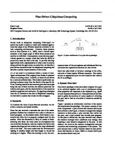
2. UBIQUITOUS COMPUTING DEVELOPMENT KIT (UCDK) The UcDK contains a range of micro-controller based modules designed to be interconnected to achieve the desired functionality. The novel feature of this kit, compared to previous designs, is its hardware biased solution to the problem of rapid prototyping this type of system. The UcDK differs from previous designs [Beigl, 2002] in that the modules in this kit are categorised by their function i.e. data link, data logging etc, and not by their physical components i.e. processor board, IO board etc. The intended design approach is to select the required hardware modules to achieve the desired functionality and connect these together using bidirectional serial communications links. These simple serial communications interfaces allow the UcDK to be easily expanded if the desired functionality cannot be obtained from the existing boards. The aim of this approach is to minimise software and hardware development times, by separating commonly required functionality into stand alone modules. At present the UcDK contains 17 hardware modules, each measuring 67mm x 52mm. The boards within this kit are classified as either: ? ? Communications : low bandwidth radio or infra-red links ? ? Processing : application specific processing modules ? ? Interfacing : external system buses, signal isolation / drivers, power supply The communication and processing boards are implemented using Atmel 89C2051 / 89C4051 microcontrollers [Atmel, 2001]. This micro-controller is based on a standard 8051 core, with up to 4K of ROM and 128 bytes of RAM. Data is passed between these boards using the on-chip serial ports. At this time the UcDK has 3 communications boards based on infra-red and radio modules. The most commonly used board is the radio data link: ? ? Radio board : omni-directional data link, based on a Radiometrix BiM2 433MHz bi-directional radio module, onboard antenna, allowing 1200 – 19.2K bps. The radio board also has an I2C port for peripheral expansion, 2 low resolution ADC channels, real time clock and up to 11 general purpose IO lines. This module has been used for a number of simple applications, having sufficient hardware resources to allow it to be a single board solution if required. An example of an application developed with the system is shown in figure 1. This is an intelligent light controller, processing sensor data from an analogue light sensor and a passive infra-red sensor, allowing this controller to turn a light on if a person is detected in a dark room. The real time clock is then used to turn the light off if nobody is detected for a pre-defined time out. The light can also be turned on and off using a push button or by commands sent over the radio link. In addition to these features, pre-emptive control of the light’s behaviour can be included. Using the real time clock, the typical usage of the light for each day of the week can be recorded, allowing the light to be turned on a few minutes in advance of its typical requirements. If this example is now viewed in a wider context, each light controller is capable of recording the activity in a room e.g. when were people moving about, sitting down etc. This information can be shared with other devices via the radio module, allowing them to combine this information with local sensor data using rule sets to enhance their operation.
Figure 1. An intelligent light controller application
When more complex functionality is required, additional processing boards can be added to form a linear array of processing modules. Typically, the head node within this array is the master node requesting services from the remaining slave nodes. The UcDK has 4 processing boards, again based upon an Atmel 89C2051 micro-controller with an I2C port for peripheral expansion, 2 low resolution ADC channels, real time clock and general purpose IO lines. In addition to these basic functions each board includes specialized components: ? ? ? ?
? ? ? ?
CPLD board: XC9572 CPLD, up to 34 GPIO lines, micro-controller data link via a SPI interface. Data logging board: up to six 32K byte EEPROM or 256 byte RAM, I2C memory devices. General purpose processing board: 4 channel I2C ADC, 1 DAC and RS232 line driver. Digital processing board: equipped with two PCF8574 devices, up to 30 digital IO lines.
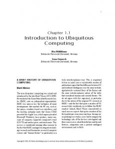
Figure 2 shows another test application, using a two-processor array to add ubiquitous computing capabilities to a cooker hob. A digital processing board (right) is connected to the hob’s internal seven segment display data bus. The state of each ring and the timer can now be monitored. This state information is sent to a radio board (left) via a serial link, allowing external devices to access this data (the radio board is mounted remotely to minimize interface from the hob). The cooker hob application demonstrates the aim of the UcDK of separating functionality into separate boards to simplify system level development, minimising software and hardware development times and debugging.
Figure 2. Cooker hob wireless interface
A number of kitchen based applications have been developed using the UcDK e.g. cooker, hob, fridge, washing machine. These are being developed as part of the York Responsive Home, led by CuTech [Cuhtec, 2004] which is aimed at evaluating ubiquitous applications in a domestic context. As a result of these experiments, an understanding of the requirements for these types of applications has been obtained and used in the development of IP cores that are used in FPGA based, SOC designs.
3. A MINIMAL CISC PROCESSOR CORE (MCP) Following the work produced using the UcDK, a number of system requirements have been identified. These system functions have been converted into matching hardware cores, to allow a FPGA based system to be developed e.g. infra-red / radio data link, serial / I2C port, GPIO, processor cores etc. To minimize development times we would like to reuse as much of the software developed in the initial UcDK prototypes as possible. This, therefore, requires a processor core that is capable of executing the 8051 instruction set. From investigation of available literature, a number of 8051 compatible cores were identified [Dcd, 2004; Koay, 2001; Cast, 2004; Oregano, 2004; Roman, 2003] : ? ? 8051 Micro-controller core : o DR8051 : VIRTEX-II o Dalton 8051 : SPARTAN-II o R8051 : VIRTEX-II o Org. 8051 : SPARTAN-II
1080 slices 87MHz 1605 slices 14MHz 1861 slices 49MHz 1250 slices
? ? RISC Emulation o PB8051 : (PicoBlaze :
330 slices 84 slices)
VIRTEX-II VIRTEX-II
113MHz
From these examples it can be seen that a true 8051 compatible core requires a significant percentage of a small FPGA’s resources. This relatively large size is due to the 8051’s architecture not mapping efficiently onto the FPGA’s resources, i.e. bit addressable memory, highly encoded instruction set etc. When these cores are combined with other IP cores required to implement the desired system, a medium sized FPGA would probably be required, with its associated increase in cost and power consumption. An alternative approach is to use software emulation [Roman, 2003], this allows a smaller RISC processor core to be used, with additional software libraries and a small amount of specialized hardware to allow it to execute 8051 instructions. This significantly reduces the amount of FPGA resources required, but still requires approximately 300 slices and, like the other cores, does not allow the processor to be optimized for a particular application or to be easily added to a SOC system bus. Therefore, an alternative approach was taken, the development of a minimal complex instruction set computer processor (MCP) core. One of the main developments in FPGA design that has permitted true SOC architectures to be developed is the increasing amount of on-chip memory. In general, this can be divided into two types; distributed and block RAM. Distributed RAM is implemented from lookup tables within the general purpose logic resources of the FPGA, whereas block RAM is a true dual port memory element, with configurable address and data bus widths, organized in columns throughout the FPGA. A typical embedded FPGA micro-controller is normally based on a RISC processor core. This processor uses block RAM for its data and instruction memory. However, its instruction decoder and control logic are constructed from general purpose logic, reducing FPGA resources that are available for peripheral devices. An alternative solution to minimise this problem is the CISC processor core. This processor again uses block RAM for its data and instruction memory and also for its control logic, as part of a microprogrammed (firmware) controller. This frees up general purpose logic, allowing more support to be included within the processor for specific applications, for peripheral devices, or simply to allow smaller, cheaper FPGAs to be used. In the 1950s Professor M.V. Wilkes first recognised that a processor’s control unit was implemented as a series of discrete steps much like an ordinary computer program [Hayes, 1988]. This lead to the development of microprogrammed control units that are commonly found in CISC processors, where each machine instruction is interpreted by a microprogram stored in control memory within the processor. These microprograms are composed of a series of microinstructions, which themselves can be composed of a series
of nanoinstructions [Katzan, 1980], defining the control signals required to perform the desired machine operation, as shown in figure 3.
uPc : micro-program counter uCm : micro-control memory uId : micro-instruction decoder
Figure 3. A typical microprogrammed controller
The processor’s instruction decoder loads the start address of the microprogram for the current program instruction into the uPc. This address is generated using general purpose logic or a translation look-up table implemented in distributed or block RAM. The choice of implementation is dependent on the instruction set’s complexity e.g. a highly encoded instruction set would probably be most efficiently implemented in a look-up table. The uPc then steps through the micro-instructions to perform the desired operation. The uCm (control memory) also specifies conditional instruction based on external signal and its associated branch address. The advantage of a microprogrammed controller is its flexibility and reduced general purpose logic requirements, allowing a standard hardware architecture to be used for a number of applications, i.e. changing the processor’s firmware (control memory) will permit the same architecture to execute different instruction sets, implement different system buses and support application specific operations through new opcodes. The size of the MCP processor can also be further reduced by only supporting those instructions required by an application i.e. the instruction decoder is edited, removing instructions that are not required; microcontrol memory is not altered since it is a fixed dedicated resource.
Figure 4. MCP Architecture
At this time five variations of the minimal CISC processor (MCP) core have been designed and synthesized in VHDL, targeted for a Xilinx Virtex II device [Xilinx, 2004]. The basic architecture is shown in figure 4. To minimise this processor’s hardware requirements consideration must be given to the FPGA’s resources: ? ? Dedicated resources : block RAM, multipliers, IOB FF ? ? LUT resources : distributed RAM, shift registers ? ? Resource sharing : buses, functional units By maximising the processor’s use of these resources and moving functionality out of hardwired logic into block RAM, general purpose logic within the FPGA will be freed up for other peripheral devices, reducing the required size and cost of the FPGA device. Two different instruction sets have been chosen for this processor, the 8051 and Xilinx’s picoBlaze RISC processor [Chapmen, 2003], allowing the performance of the MCP processor’s architecture to be compared with existing FPGA based systems and significantly different instruction sets. To support these different instruction sets the processor’s instruction decoder (Id) and control memory (uCm) have been modified, however the remaining functional units are unaltered. Another advantage of this approach is that using an existing instruction set removes the need to develop specialized software tools e.g. assembler etc. To benchmark this processor’s performance an equivalent picoBlaze system has been developed. This processor has been slightly modified to allow it to connect to a wishbone system bus [Silicore, 2003]. The hardware requirements, using a wishbone bus with two 8 bit output ports are given in Table 1 : Model
ROM bytes
RAM bytes
Clock Freq
114 133
256 2048
256 2048
45.3 MHz 71.7 MHz
136
65536
2048
72.1 MHz
135
2048
2048
78.8 MHz
133
65536
2048
78.8 MHz
154
2048
2048
76.4 MHz
Slices
Picoblaze : internal instruction memory MCP : internal instruction memory, picoBlaze instruction set MCP : external instruction memory, picoBlaze instruction set MCP : internal instruction memory, 8051 instruction set MCP : external instruction memory, 8051 instruction set MCP : internal instruction memory, 8051 instruction set, with 16 bit internal architecture
Table 1. Comparison of hardware requirements of various CPU models tested
The MCP processor can be implemented with internal (block RAM) or external (EPROM) instruction memory (IMEM). The external instruction memory greatly simplifies debugging by allowing the instruction trace to be monitored via a logic analyzer. The main disadvantages of this implementation is that an external memory controller is required and that the system clock speed is now limited to the access time of the external memory devices. An external memory version of the picoBlaze processor was not possible since this implementation does not fully support the wishbone bus standard. In addition to the standard MCP architecture a 16 bit 8051 version has been produced. This version of the processor has been optimised to support 16 bit operands, having a 16 bit ALU and internal data paths. It also has additional hardware and micro-code support for the particular application for which it was developed. Micro-code support is also used in all versions of the MCP processor to control data transfers on the wishbone bus. To allow a complete FPGA based solution to be constructed, a number of peripheral cores have been developed. The cores were identified from the system requirements produced when developing the initial UcDK prototypes. At present these peripheral cores have been synthesized for a Virtex II FPGA and use a wishbone interface allowing them to be easily combined to form a SOC architecture, these include : ? ? ? ?
? ? ? ?
Timer: 8 bit, configurable pre-scale (default 32) - Number of Slices : 15 Slices GPIO : 8 bit input / output port - Number of Slices : 9 slices Serial port : rx / tx FIFOs - Number of Slices : 46 I2C : single master - Number of Slices : 134 Slices
? ? IRDA : signal encode/decode - Number of Slices : 63 Slices ? ? Radio : signal encode/decode, rx / tx FIFOs, error detection - Number of Slices : 110 Slices From these result it can be seen that complex hardware components such as the radio and I2C ports use approximately the same amount of FPGA resources as a MCP core. If the selected FPGA contains sufficient block RAM elements an alternative approach would be to use MCP cores to emulate these hardware components, increasing their flexibility. This is particularly useful for the radio port, allowing the same hardware to be used for different protocols by changing the appropriate software subroutines. The disadvantage of this approach is a reduction in performance i.e. a hardware implementation allows parallel operations, whilst a MCP implementation is based on sequential code. Radio and I2C software routines have been developed for the 8051 version of the MCP, using GPIO lines and a periodic interrupt timer: ? ? Radio port - ROM: 560 bytes, RAM: 29 bytes ? ? I2C port - ROM: 509 bytes, RAM: 6 bytes By selecting an appropriate system clock speed to support the desired data rates, a single MCP processor has sufficient memory resources to emulate multiple functional units. Initial development has been implemented on a Virtex II FPGA board we have developed, as shown in figure 5, which supports FPGA devices up to six million gates. This board also has onboard voltage regulators, FLASH memory and a CPLD configuration engine allowing it to be used for complex, stand alone ubiquitous computing applications. We are also currently developing a Spartan III [Xilinx, 2003] version of this board for the types of application we have described in this paper i.e. small, cheap mass-produced applications. Virtex II FPGA board Test points External instruction memory
Figure 5. FPGA development board
The Virtex II board has been used to develop a FPGA based light controller as shown in figure 1. This system uses the following IP cores: ? ? ? ? ?
? ? ? ? ?
Timer : 8 bit with configurable pre-scale - Number of Slices : 15 GPIO : 8 bit input / output port - Number of Slices : 9 Serial port : rx / tx FIFOs - Number of Slices : 46 Radio : signal encoding / decoding, rx / tx FIFOs, error detection - Number of Slices : 110 MCP : internal instruction memory, picoBlaze instruction set - Number of Slices : 133
Although a serial port is not required to achieve the desired functionality it was included for debugging purposes. When implemented this design would require 322 slices of a Virtex II device. An additional 25 slices are required to implement the wishbone bus e.g. data multiplexers and address decoding logic. Therefore, this design would require a XC2V80 device compared to a XC2V250 or XC2V500 device if a traditional 8051 processor core were used.
4. CONCLUSIONS This paper has presented initial work into developing component technologies for future pervasive computing environments. An ubiquitous computing development kit has been developed in order to allow rapid prototyping of embedded processor and ubiquitous computing applications. The design emphasis for this kit is to minimise software and hardware development times by using a number of application specific hardware modules. From initial prototype applications based on this kit, a number of system requirements for ubiquitous computing applications have been identified. These have lead to the development of a minimal CISC processor and other IP cores for FPGA devices. Implementing microcontrol memory in dedicated block RAM storage elements has reduced the amount of general purpose logic required by this processor core, reducing the size and cost of the required FPGA device, allowing increased system integration and complexity. Further size optimizations can also be achieved with this processor by only supporting those opcodes required by an application and emulating peripheral cores in software.
5. REFERENCES Atmel, (2001), 8-bit microcontroller with 4K bytes flash : AT89C4051, WWW: http://www.atmel.com Beigl, M., Zimmer T., Krohn A, Decker C., Robinson P., (2002), Smart-Its – communication and sensing technology for UbiComp environments, WWW: http://ubicomp.teco.edu/publ.html CAST,(2004), R8051 8-bit RISC like microcoller core, WWW: http://www.cast-inc.com/cores/r8051/cast_r8051-z.pdf Chapmen K., February (2003), PicoBlaze 8 bit microcontroller for Virtex-E and Spartan-II/IIE devices, XAPP213(v2.1), WWW: http://www.xilinx.com CUHTEC, (2004), The Centre for Usable Technology, WWW: http://www.cuhtec.org.uk Digital core design, DR8051 IP CORE http://www.hitechglobal.com/ipcores/dr8051.htm
(High
performance
8-bit
Micro-controller),
WWW:
Hayes J.P., (1988), Computer architecture and organization, McGraw-Hill, ISBN 0-07-027366-9 Katzan H., (1980) Microprogramming primer, McGraw-Hill, ISBN 0-07-033387-4 Koay Kah Hoe (2001), Implementation of http://www1.mmu1.edu.my/~khoay/8051core.htm
8051
microcontroller
core
in
Xilinx
FPGA,
WWW:
Oregano Systems, (2004), 8051 IP Core, WWW: http://www.oregano.at/ip/8051.htm Roman-Jones Inc, (2003), PicoBlaze emulated 8051 microcontroller (PB8051-MX/TF), http://www.xilinx.com/products/logicore/alliance/roman_jones/romanjones_pb8051_microcontroller.pdf
WWW
:
Schmidt, A., Van Laerhoven K., (August 2001), How to Build Smart Appliances? IEEE Personal Communications 8(4), pp. 66-71.
Silicore, (2002), Wishbone System-on-chip (SOC) Interconnection Architecture for Portable IP Cores, WWW: http://www.opencores.org/projects.cgi/web/wishbone/wbspec_b3.pdf Wejchert, J., (February 2000), “The Disappearing Computer”, Information Document, IST Call for proposals, European Commission, Future and Emerging Technologies., WWW: http://www.disappearing-computer.net/mission.html Xilinx (June 2004), Virtex-II Platform FPGAs: http://direct.xilinx.com/bvdocs/publications/ds031.pdf
Complete
Data
Sheet,
DS031
(v3.3),
WWW:
Xilinx, (July 2003), Spartan – 3 1.2V FPGA Family: Functional description, DS099-2 (v1.2), WWW: http://www.xilinx.com