Developing with UML - Goodies, Pitfalls, Workarounds Martin Hitz1, Gerti Kappel2 1
Department of Data Engineering Institute of Applied Computer Science and Information Systems University of Vienna A-1010 Vienna, Austria
[email protected] 2 Department of Information Systems Institute of Applied Computer Science Johannes Kepler University of Linz A-4040 Linz, Austria
[email protected]
Abstract. The object-oriented modeling language UML offers various notations for all phases of application development. The user is left alone, however, when applying UML in up-to-date application development involving distribution, data management, and component-oriented mechanisms. Moreover, various shortcomings have been encountered, most notably w.r.t. refinement of model elements throughout the development life cycle and employment of interaction diagrams to formalize use cases. The paper will shed some light on how these issues may be handled with UML.
1
Introduction
"When it comes down to it, the real point of software development is cutting code. Diagrams are, after all, just pretty pictures." [4, p.7] This opinion is still alive among researchers working in the area of software development as well as practitioners involved in software projects. Nonetheless, it has been more and more commonly accepted that the early phases of software development such as requirements specification, analysis, and design are key to the successful development and deployment of software systems. Not least due to the usage of some intuitive but rigor diagrammatic notations representing the artifacts of these development phases the software development process has been improved considerably. Object-oriented software development follows the same lines of thought. From the very beginning of requirements specification on, object-oriented modeling notations provide intuitive mechanisms for representing the objects and their interactions for reaching a common goal, namely the required system functionality.
Several object-oriented modeling notations and methods had been developed in the late eighties and early nineties (for an overview we refer to [5]). After different merging efforts and a request for proposal by the Object Management Group, UML (Unified Modeling Language) was adopted in November 1997 as the official industry standard for object-oriented software design notations [3, 4]. UML covers several advantages, among which only three shall be mentioned at this place. First and most importantly, the standardization of UML helps to bypass notational discussions and to concentrate on the real problems, such as modeling guidelines and design heuristics, proper development process, and proper tool support. Second, UML represents the fusion of the Booch method, Jacobson’s Objectory, and Rumbaugh’s OMT. As such and thanks to Objectory, the very first step of object-oriented modeling encompasses not the finding of the objects of the problem domain - as has been the case in most other object-oriented modeling techniques - but the identification of the system functionality as required by the users. These so called use cases correspond to what has been depicted in level zero data flow diagrams known from traditional structured analysis. With use cases it has been possible both to overcome the "everything is an object and everything taken from structured development is bad"-mentality and to concentrate at the very beginning of software development on the user’s requirements, which is just functionality and not objects. And third, different model views supported by UML allow to comprehend a complex system in terms of its essential characteristics. These are its system functionality (use case view), its internal static and dynamic structure (logical view), its synchronization behavior (concurrency view), and its implementation and physical layout (deployment view, component view) [3]. We won’t dig into a further discussion of UML’s goodies, but rather concentrate on suffered pitfalls (which is more interesting anyway). The main problems encountered during the development of a web-based calendar manager [8] are due to UML´s partially sloppy definition of notations, which lack a precise semantic specification. The main contribution of this paper is to shed some light on some of these deficiencies and discuss possible workarounds, some of which may be considered as suggestions of future enhancements of the notation. In the next section some refinements of UML constructs are discussed. Section 3 concentrates on the employment of interaction diagrams to formalize use cases. Finally, Section 4 points to the development of data-intensive, distributed applications based on component technology. Section 5 concludes the paper.
2
Refinement of Models
Development of complex systems based on various model views requires that the modeled diagrams can be related to each other for the purpose of traceability, i.e., connecting two model elements that represent the same concept at different levels of granularity. In addition, consistency checking between various model views representing different though overlapping characteristics of the system at hand is a prerequisite for correct system development. Last but not least, most applications
have to cope dynamically with changing requirements. Thus, various kinds of evolution mechanisms should be provided by the modeling notation. To adequately support traceability, consistency checking, and evolution, UML should provide for the refinement of model elements. In this context, refinement refers to "... a historical or derivation connection between two model elements with a mapping (not necessarily complete) between them." [16, p.71]. In the following we will question some of UML’s refinement mechanisms. We will investigate use case diagrams, class diagrams, and statechart diagrams. Sequence diagrams are discussed in the context of use case diagrams, too.
2.1
Refinement of Use Case Diagrams
A use case represents some system functionality. Several use cases together depicted in a use case diagram make up the whole system to be implemented. To support both reuse and the stepwise specification of the required functionality, two use case relationships are provided by UML, the extends relationship, and the uses relationship. Their precise meaning, however, is only poorly specified. A A
“inner”
B
A
B
“super” B
Fig. 1. Extends relationship between two use cases
Concerning the extends relationship, in [16, p.78] it is stated that if use case A extends use case B then an instance of use case B may include the behavior specified by A. Figure 1 depicts such a use case relationship. In the object-oriented literature there are two well-known interpretations for this relationship, which are captured by the inner concept of Beta and the super concept of Smalltalk, respectively. In Beta [12], the keyword inner may be placed somewhere within the implementation of an operation B (in analogy to use case B) of some object class B’. Within some subclass A’ of B’, the implementation of B may be overridden. During runtime, if the operation B is invoked on an instance of A’, not only the implementation of A’ but also the one of B’ gets executed in such a way, that the inner construct is replaced with the specialized implementation and the such extended implementation of B is executed (cf. lower left part of Figure 1, where the implementation of a use case is depicted as a sequence diagram). The inner construct in Beta specifies an unambiguous place in the implementation of an operation where to insert specialized code.
In Smalltalk, the keyword super may be placed somewhere within the specialized implementation of the operation A (in analogy to use case A) of some class A’, and always refers to the class’ superclass. Forwarding the message to super, it is possible to invoke the overridden implementation of the respective operation in the superclass within the specialized implementation of the subclass (cf. lower right part of Figure 1). Again, the exact location of this forwarding plays a crucial role. Both interpretations rely on the exact definition where the behavior extension takes place, but this is not possible in UML. Although extension points may be specified in the original use case (cf. definition of extension points in [17, p.95]), these extension points are just declared within the elliptic representation of the use case but there is no referencing mechanism from within the corresponding sequence diagrams. Concerning the uses relationship, in [16, p.78] it is stated that if use case A uses use case B then an instance of use case A will also include the behavior as specified by B. Figure 2 depicts such a use case relationship. Again, in UML the exact interpretation of this uses relationship is left unspecified. There is no indication in the implementation of use case A where to include the behavior of B. For both refinement relationships, probes as defined in Objectory [9] may be used as a workaround. A probe is a position in the implementation of a use case, i.e., in a sequence diagram, where an additional behavior can be inserted (cf. lower part of Figure 2). It should be easy to include an appropriate notation in UML. A
B
B
A
B
Fig. 2. Uses relationship between two use cases
2.2
Refinement of Class Diagrams
Although the UML standards document states that the details of specifying the refinement, i.e., the derivation, are beyond the scope of UML [17, p.46], there should be at least some notational conventions provided to support any of traceability, consistency checking, and evolution. Especially the evolution from an analysis document to a design document should be supported. A class diagram is a typical example of such a "moving target". Object classes, associations, and generalizations are deleted and added, and multiplicities and directions of associations are changed, to mention just a few. A recurring pattern of class evolution is shown in Figure 3. There,
a one-to-many association between object class X and object class Y is further inserted between X and Y. X
X
1
α1
α
1
1
Y_Set
*
Y
α2 *
Y
Fig. 3. Refinement of class diagrams
Since the object-oriented paradigm is strong at modeling single objects and navigation among them but falls short at working with sets of objects, container classes are heavily used helper classes. In a car reservation system, for example, if some client wants to reserve a car the availability of all the cars has to be checked to find the optimal car. This is a typical operation to be invoked on a set of objects, namely cars. Thus, either the operation is modeled in terms of a class operation or a container class is inserted holding sets of cars. In the latter case, the availability check would be invoked on instances of the container class. Besides constraints, which may be specified arbitrarily, UML provides no mechanism to annotate the derivation, e.g., that association α has evolved into α1 and α2, and the class Y_Set has been inserted. Bergner et al. have drawn similar conclusions and have suggested extensions to the refinement notation [1]. To increase standardization and portability, the definition of the precise semantics of the most common derivation rules should not only be left to some UML CASE tool designers.
2.3
Inheritance of Statechart Diagrams
Refinement of statechart diagrams is properly supported as far as state refinement is concerned. State refinement comes in two different flavors, and-refinement, which implies that the original state is decomposed into a set of parallel substates, and orrefinement, which implies that the original state is decomposed into a statechart again. However, the refinement of statechart diagrams must also be seen in the light of the inheritance of statecharts. The reason is the following. In general, object classes are organized in class hierarchies, in which subclasses inherit the structure as well as the behavior of superclasses. As far as the inheritance of behavior is concerned, the discussion has mainly focused on inheritance of single operations in the past. Object behavior, however, is specified at two interrelated levels of detail: at the operation level and at the object class level. The latter is specified in terms of object life cycles that identify legal sequences of states and state changes, i.e., operations. In UML, object life cycles are modeled in terms of statechart diagrams, i.e., inheritance of object life cycles has to be treated in the realm of inheritance of statechart diagrams.
Whereas there exist a common understanding on the inheritance of single operations in terms of inheriting their signatures and implementations, and specializing them [18], there exist no common understanding on how to specialize object life cycles in terms of specializing statechart diagrams and which criteria to follow. The encountered problems are briefly investigated in the following. There are several possibilities to inherit and to specialize object life cycles ranging from no restriction at all, called arbitrary inheritance, to allowing no specialization at all, called strict inheritance. Whereas the former does not support any notion of substitutability in the sense that an instance of a subclass can be used when an instance of a superclass is expected [18], the latter prohibits the specification of new operations in the subclass at all. Whereas the former notion is too unrestricted to build reusable and reliable systems, the latter notion is too restrictive. What would be necessary instead is a common understanding of the notion of consistent inheritance. Two alternative notions of consistent inheritance prevail: covariance and contravariance. Covariance requires that input and output parameters be restricted to subclasses and that pre- and postconditions of operations be strengthened when operations are redefined for a subclass. Contravariance requires that input parameters be generalized to superclasses and preconditions be weakened, while output parameters be restricted to subclasses and postconditions be strengthened. Covariance is favored by object-oriented modeling methods as it supports the concept of specialization in the tradition of conceptual modeling and knowledge representation [13]. Contravariance is favored by programming language folks as it supports strong type checking in the presence of type substitutability [18]. cancel checkAvailability create s1 s0
confirm s2
s5
s7
consume
makeInsurance
payCancellationFee
s3
pay
s4
s6
sendSorryLetter
Fig. 4. Statechart diagram of object class RESERVATION plus extensions Object life cycles may be specialized by extension and by refinement. Extension means adding states and transitions. Refinement means expanding inherited states into substatechart diagrams, which consist of newly added states and transitions in turn. Whereas the latter has been treated more thoroughly in the literature (for an overview, we refer to [6, 15]), even within the UML standards document (see below), there is less attention paid to the former. We will discuss some peculiarities of inheritance by extension in the following.
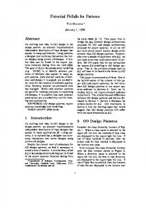
Consider the unshaded states of Figure 4, which depict the life cycle of a generic class RESERVATION (gray shaded states and incident transitions are considered below). A reservation object is created, the availability of the thing to be reserved is checked, and the reservation is either confirmed or a sorry letter is sent. After the reservation is consumed, it has to be paid. Let’s assume a subclass CAR_RESERVATION, which extends the inherited life cycle in that the signing of an insurance contract is added (cf. light-gray shaded states in Figure 4). This parallel extension seems to be most intuitive and a frequently recurring pattern in reality. Parallel extension implies the covariant notion of consistent inheritance in that both the postcondition of the inherited transition confirm and the precondition of the inherited transition pay are strengthened (preconditions and postconditions of transitions are their prestates and poststates, respectively; in the example: post(confirm) = {s2} and pre(pay) = {s3} for the superclass, and post(confirm) = {s2, s5} and pre(pay) = {s3, s6} for the subclass). If one wants to adhere to the notion of type substitutability, one would have to disregard parallel extension, and support only alternative extensions in some subclasses. Let’s assume a subclass RESERVATION_WITH_CANCEL of class RESERVATION, which extends the inherited life cycle with the possibility to cancel the reservation (cf. dark-gray shaded states in Figure 4). This alternative extension implies the contravariant notion of consistent inheritance, in that no inherited conditions and no inherited types of parameters are changed. The interpretation of covariant and contravariant inheritance is further elaborated on by Ebert et al. [2] along the following lines: Parallel extension conforms to covariant inheritance, which implies observation consistency, i.e., any instance of a subclass may be observed like an instance of a superclass disregarding the added states and state transitions. Alternative extension conforms to contravariant inheritance, which implies invocation consistency, i.e., on any instance of a subclass each operation of the superclass may be invoked disregarding the added states and state transitions. Observation consistency and invocation consistency exclude each other. For a detailed discussion and formal proof thereof, we refer to [2, 11, 14]. Extension mechanisms of statechart diagrams are not discussed at all in the UML standards document. Refinement of statechart diagrams is discussed to that effect that "... state machine refinement as defined here does not specify or favor any specific policy of state machine refinement. Instead, it simply provides a flexible mechanism that allows subtyping (behavioral compatibility), inheritance (implementation reuse), or general refinement policies.’’ [17, p.117]. With the above considerations in mind, we would advocate for a more complete notion of inheritance of statecharts within the realm of UML. More specifically, within the statechart diagram of a subclass, the inherited parts should be clearly distinguishable from the newly defined ones. Possible solutions may include shading of inherited states or qualifying state names with the class names where they have been originally defined.
3
Formalizing Use Cases
A use case provides a high-level, rather abstract notion for representing some required system functionality. If one wants to show how this use case is realized by the underlying objects and their interactions, one has to formalize use cases in terms of sequence diagrams, and collaboration diagrams, respectively. Since sequence diagrams and collaboration diagrams are deemed equivalent in terms of expressive power, we concentrate in the following on sequence diagrams. We have extensively used them in the realm of our calendar management system. Some of the encountered problems and possible workarounds are discussed in the following. Concerning class operations, it is not specified how they are represented in sequence diagrams, besides the special class operation create. Due to the representation of time in sequence diagrams it is not possible to depict general purpose class operations like create operations, i.e., leading to the box representing the object. Instead, it would be possible to borrow class diagram notation and underline any class operation. Another solution would be to represent the respective class as an object and thus be able to handle each class operation like any other object operation. The flaw of both solutions concerns the different notations for class operations, one for create operations, and one for all the other class operations. Concerning set operations, the equivalence of multiobjects in collaboration diagrams has been left out in sequence diagrams. Multiobjects are a convenient mechanism especially for data intensive applications where sets of objects are involved. A possible solution to iterate over objects in a set is discussed below. : Calendar
i: Participant
c: CV
update()
update()
∀ CVs c of Participant i ∀ Participants i
Fig. 5. Implementation of use case Update_View
Concerning the objective of sequence diagrams, they are used for representing either scenarios or algorithms. Concerning the former, it is an intuitive way to capture the main idea of a use case, however, only one possible execution path is depicted. If one prefers a rather complete specification of the use case’s semantics, one would have to use sequence diagrams for representing whole algorithms including iterations and conditional execution paths. In particular, iterations are poorly specified within sequence diagrams. Consider the sequence diagram in Figure 5, which depicts the implementation of the use case Update_View within our calendar manager. The purpose of this use case is to inform all participants of a date that something has
changed, e.g., a date has been inserted, or its begin time has been moved. Thus, the operation update() is invoked on all participants of the respective date. In the UML standard document, there is no indication on how to represent messages sent to each object of a set. We suggest to index the objects of a set by some iteration variable, and use this index also as object name at the top of the respective lifeline (cf. ∀ Participants i and i:Participant in Figure 5). The nesting of iterations is treated in an analogous way. Referring to Figure 5, for each participant the message update() is sent to each client view of that participant displaying his/her personal calendar (cf. ∀ CVs c of Participant i in Figure 5). : UI
: Calendar
insertDate(...)
create()
: Date
createNot()
create()
n: Notification
addParticip(PIDi)) add(PIDi) i = 1..n
add(PIDi)
Update_View
Fig. 6. Implementation of use case Insert_Date
Last but not least, concerning the inclusion of component sequence diagrams into more complex sequence diagrams in analogy to subprogram calls, there is no discussion thereof in the standards document. We suggest to use probes from Objectory to precisely specify where and when to include another sequence diagram (cf. discussion on uses relationship of use case diagrams in subsection 2.1). Figure 6 shows the usage of probes. There, within the implementation of the use case Insert_Date, the use case Update_View is called. Another extension, which is depicted in Figure 6, refers to the dynamic creation of a (possibly variable) set of objects and the interaction with those objects. We borrow the notion of multiobjects from collaboration diagrams. Messages to multiobjects address the entire set (exhibiting cascading semantics in general), whereas in order to communicate with a single element of the multiobject, the former has to be explicitly depicted with a separate lifeline (not shown in Figure 6). Our system supports at most three notifications per date. The corresponding multiobject and its elements are constructed by the create message. For each participant, all notification objects are informed of his existence via the add message to the multiobject, which is assumed to be cascaded to the element objects.
4
Component-Based Development
This section on component-based development does not provide any solutions. Rather its purpose is to give a quick tour on various topics on component-based development, which all point to open research issues. Similar to the question posed on objects ten years ago, it has still to be clarified what a component is all about. The least common denominator may define a component being a reusable artifact. Thus, it encapsulates certain functionality and provides a clear notion of interface to use this functionality. Figure 7 depicts two dimensions to classify components, based on the kinds of artifacts, and on the kinds of software development phases, where components are reused. Along the artifacts axis, we may distinguish executable objects, class descriptions, patterns of reusable knowledge, frameworks in the sense of patterns with inversion of control [10], and whole executable programs. Along the phases axis, reusability may occur during all software development phases ranging from requirements specification to implementation. An interesting topic of research remains to look into each combination of the two dimensions and investigate their relevance for component technology in turn. Artifacts Programme Framework Pattern Class Object
Phases Implementation
Design
Analysis Requ.Spec.
Fig. 7. Kinds of reusable artifacts
UML supports the notion of components. There, "a component is a reusable part that provides the physical packaging of model elements.’’ [17, p.45] Thus, in UML a component is a very low-level, implementation oriented notion. In other words, it is a physical component, which comprises either source code or executable code. However, we feel that this is not enough. To explore the whole potential of reusability, there should be also the notion of a logical component with a clear interface definition supporting both the notion of a provided interface and a required interface. Examples thereof exist in the literature. Subsystems in RDD [19] have contracts, which enclose the provided functionality to the "outside world’’. At the same time, RDD also supports the notion of collaborators, which are other object classes necessary to fulfill the functionality of the object class at hand. Thus, collaborators and their provided operations make up the required interface of the respective object class.
Another question concerns the packaging of functionality within components. Components may be fine-grained encapsulating some small functionality, e.g., a sort algorithm, or they are coarse-grained encapsulating whole applications. Concerning up-to-date application development including distribution and database functionality, we also regard components as a possible mechanism to encapsulate various levels of implementation details and to provide an easy-to-use interface to connect to some database and to use some underlying distribution mechanism, respectively. We feel that the component notation provided by UML is by far not sufficient. It seems, however, that the software development community has not yet agreed upon a uniform notion of component based development. Thus, defining a standard notation might be premature at this point of time.
5
Conclusion
"When it comes down to it, the real point of software development is cutting code. Diagrams are, after all, just pretty pictures." [4, p.7] The purpose of the paper was to demonstrate that UML in its present state is still suffering a certain lack of expressive power as well as several weaknesses in its definitions. Thus, blames of the kind cited above can be hardly refuted at present.
References 1. Bergner, K. et al.: A Critical Look at UML1.0. The Unified Modeling Language Technical Aspects and Applications, M. Schader and A. Korthaus (eds.), Physica-Verlag (1998) 2. Ebert, J., Engels, G.: Observable or Invokable Behavior - You have to Choose! Technical Report, Institute of Computer Science, Leiden University (1994) 3. Eriksson, H.-E., Penker, M.:UML Toolkit. John Wiley & Sons (1998) 4. Fowler, M.: UML Distilled: Applying the Standard Object Modeling Notation. Addison Wesley (1997) 5. Fowler, M.: A Survey of Object-Oriented Analyses and Design Methods. Tutorial Notes of European Conference on Object-Oriented Programming (ECOOP) 1996, Linz/Austria (1996) 6. Harel, D., Gery, E.: Executable Object Modeling with Statecharts. IEEE Computer, 30 (7), p. 31-42 (July 1997) 7. Harmon, P., Watson, M.: Understanding UML - The Developer’s Guide with a Web-based Application in Java. Morgan-Kaufmann (1998) 8. Hitz, M., Kappel, G.: Software Development with UML. dpunkt Verlag (1998) (in preparation, in German) 9. Jacobson, I., Christerson, M., Jonsson, P., Oevergaard, G.: Object-Oriented Software Engineering - A Use Case Driven Approach. Addison-Wesley (1992) 10. Johnson, R.E.: Frameworks = Components + Patterns. Communications of the ACM, 40 (10), p. 39-42 (October 1997)
11. Kappel, G., Schrefl, M.: Inheritance of Object Behavior - Consistent Extensions of Object Life Cycles. Extending Information Systems Technology, Proceedings of the Second International East/West Database Workshop, J. Eder and L. Kalinichenko (eds.), SpringerVerlag , Workshop in Computing Surveys, (1994) 12. Lehrmann Madsen, O., Moller-Pedersen, B., Nygaard, K.: Object-Oriented Programming in the Beta Programming Language. Addison Wesley (1993) 13. Mylopoulos, J.: Object-Oriented and Knowledge Representation. Proceedings of the IFIP TC2 Working Conference on Object-Oriented Databases (DS-4), R. Meersman and W. Kent (eds.), North-Holland (1990) 14. Schrefl, M., Stumptner, M.: Behavior Consistent Extension of Object Life Circles. Proceedings of the International Conference on Object-Oriented and Entity-Relationship Modeling, LNCS Vol. 1021, Springer-Verlag (1995) 15. Schrefl, M., Stumptner, M.: Behavior Consistent Refinement of Object Life Cycles. Proceedings of the 16th International Conference on Entity-Relationship Modeling, Springer-Verlag LNCS (1997) 16. UML Notation Guide. Version 1.1, Rational Software (September 1997) 17. UML Semantics, Version 1.1, Rational Software (September 1997) 18. Wegner, P., Zdonik, S.B.: Inheritance as an Incremental Modification Mechanism or What Like Is and Isn’t Like. European Conference on Object-Oriented Programming (ECOOP 1988), S. Gjessing and K. Nygaard (eds), Springer LNCS 322, p. 55-77 (August 1988) 19. Wirfs-Brock, R., Wilkerson, B., Wiener, L.: Designing Object-Oriented Software. Prentice Hall (1990)