2009 International Conference on Emerging Trends in Electronic and Photonic Devices & Systems (ELECTRO-2009)
Development and cold testing of vacuum RF window for C band 250 kW CW power klystron O S Lamba, Meenu Kaushik, Sushil Kumar, Vishnu Jindal, Vijay Singh, Shilpam Ratan , Debasish Pal, D Kant and L M Joshi Microwave Tubes Area. Central Electronics Engineering Research Institute Pilani(Rajasthan):333031 (Council of Scientific and Industrial Research, New Delhi) Email:
[email protected] Specifications of C-band klystron:
Abstract:-The paper deals with the design fabrication and cold testing of vacuum RF window for C-band 250 kW CW power klystron. The simulation of the window has been carried out using the CST microwave studio software. The proposed window is designed for 5 GHz operating frequency for handling 250 kW of RF power. In the proposed window geometry, metallized alumina disc (99.5 % purity) of diameter 56 mm and thickness 1.5 mm is brazed in a cylindrical waveguide of diameter 56 mm. The cylindrical waveguide is terminated to WR 187 waveguide at its both ends. The return loss and insertion loss of the above mentioned window has been found to be –48 dB and 0.05 dB respectively which are well matched with experimental values. The bandwidth of 170 MHz was achieved. The window performance has been found satisfactory for microwave transmission.
Operating Frequency: 5 GHz Output Power : 250 kW Beam Voltage : 60 KV Beam Current : 10 Amps Focusing : Electromagnet Efficiency : > 40 % Gain : > 45 dB II. WINDOW DESIGN The electrical design parameters for the window are: thickness, diameter and dielectric constant of alumina disc, diameter and length of waveguide etc. The window performance is decided from the output results of the software in term of return loss, VSWR, insertion loss, bandwidth etc. Input parameters for the software are input frequency range, window dimensions and dielectric constant of the ceramic disc. To obtain the best results of scattering parameters, different combination of input parameters have been entered and corresponding outputs have been checked in terms of scattering parameters.. The simulation has been carried out with CST microwave studio code. The disc thickness, diameter and W/G length are variable parameters to optimize return loss and insertion loss values. (a) Input Design Parameters:
Keywords: RF Window, Klystron, pill-box type, alumina, S parameters
I. INTRODUCTION RF window is one of the important issue for developing the high power klystrons. RF window is a critical component of all microwave high power tubes and is used on the output section of the device for the transport of microwave power from vacuum to external pressurized atmosphere. RF window is a passive component that must be transparent to microwaves and hold ultra high vacuum. The desired features of an ideal window are: minimum reflection, minimum insertion loss, high power handling capability, wide bandwidth, excellent mechanical strength, high thermal shock resistance and vacuum tightness. Pill-box type microwave windows are generally preferred for high power klystrons due to their higher capacity for handling high peak and average rf power. The other functional advantages are broad bandwidth and easy impedance matching with the rest of the transmission line[4].The design studies on high power RF windows are motivated by the need for C band 250 kW CW power klystron which is under development at CEERI Pilani.
Window Material : Alumina Loss Tangent of Disc: 0.0002 Dielectric Constant: 9.4 Disc diameter: 56 mm; Disc thickness: 1.5 mm Circular W/G diameter: 56 mm; Circular W/G length : 25.01mm; Rectangular W/G length: 30 mm Input and output W/G (WR187): a= 47.55 mm, b=22.15 mm
429
2009 International Conference on Emerging Trends in Electronic and Photonic Devices & Systems (ELECTRO-2009)
make the vacuum tight joint. The copper part has been made thin to make it ductile so that the seal may remain intact instead of mismatching of thermal expansion of both materials. The brazed window is leak checked on helium leak detector of sensitivity of 1x10 –10 torr lit/sec[1]. The brazed window is shown below in Fig. 3
The schematic view of pillbox type RF window is shown in Fig.1 in which ceramic disc is sandwiched in between circular W/G and other ends terminated in standard WR 187 wave guides.
Fig.1:Schematic view of pillbox type RF window
The electromagnetic simulation of RF windows carried out using CST Microwave Studio Code and HFSS code. We have optimized the return loss and insertion loss not only at the desired frequency but also in the entire range of desired bandwidths. The simulated return loss and insertion loss finally obtained at 5 GHz are –35.7 dB and 0.016 dB respectively.Fig.2 shows the plot of Return loss and Insertion Loss in the desired frequency range[2].
Fig. 3: RF window parts
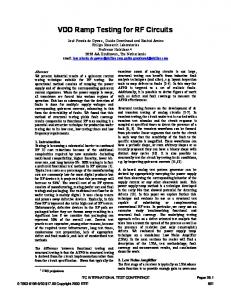
IV. COLD TESTING RESULTS The simulation results of alumina window of 56 mm disc diameter, 1.5 mm disc thickness are tabulated in Table 1. The plots of Return Loss, Insertion Loss v/s frequency have been obtained through the software as well as experiments which are shown in fig. 2. and Table1. The nominal length of window has been optimized to 25.55 mm and corresponding return loss –44.4 dB and insertion loss –0.059dB at 5 GHz frequency. Cold test measurements were carried out on two fabricated window of length 24.55 mm and 24.40 mm. The measured return loss and insertion loss finally obtained at 5.022 GHz are –50.36 dB and 0.038 dB respectively[3]. The measured results are shown in table 2.
Fig.2 Plot of Return Loss & Insertion Loss
The window performance was evaluated by variation of dielectric constant of disc and length of wave guides. The variation results are shown in Table 2.
Table2 : Cold test results Table:1 Window performance with dielectric constant variation
S.
Dielectric
Frequency
Return
Insertion
No.
constant
(GHz)
Loss(dB)
Loss(dB)
1.
9.2
5.079
-69.77
-0.0022
2.
9.3
5.0395
-71.96
-0.0021
3.
9.4
4.999
-71.47
-0.0022
4.
9.5
4.962
66.828
-0.0022
5.
9.6
4.9226
-70.75
-0.0022
WINDOW1 Diameter : 56mm Length : 24.55mm Disc thickness : 1.50 mm Material :Alumina
Measu-red Return loss(dB)
Measu-red Insertion loss(dB)
-44.4 dB
-0.059
-48.6 dB
-0.0679
WINDOW 2 Diameter : 56mm Length : 24.40mm Disc thickness : 1.50mm Material : Alumina
V. CONCLUSION
III. WINDOW BRAZING:
Electromagnetic design of pillbox-type RF window for high power C-band klystron has been carried out using “CST Microwave Studio” and "Ansoft HFSS" software. The simulated results have been validated through cold testing of few RF windows. The variation of dielectric constant, window length, diameter, disc thickness parameters simulated .to achieve the desired window performance. RF window for C band 250 kW CW Klystron alumina disc of 56 mm diameter and 1.5 mm thickness and 24.55 mm length has been designed, fabricated and cold testing is carried out. The
The RF window is an integral part of high power klystron tube. In order to maintain ultra high vacuum the window should be capable of holding vacuum of the order of 10 –9 torr. The alumina disc is metallized and brazed on the circumference with OFHC copper waveguide, with cylindrical part made extra thin at the joint area, and the disc is pushed to be fitted in it. A molybdenum wire clamp is placed on the outside of the waveguide in this region to keep the copper from expanding away from the ceramic during brazing. Palladium brazing alloy with MP 850 0 C has been used to
430
2009 International Conference on Emerging Trends in Electronic and Photonic Devices & Systems (ELECTRO-2009)
performance of window found satisfactorily for using at 5 GHz operating frequency.
Fig 4 Measured Return Loss & Insertion Loss of the window.
ACKNOWLEDGMENT
The authors are thankful to Dr SN Joshi, Emeritus Scientist for his encouragement and guidance and Dr. Chandra Shekhar , Director, CEERI for allowing to send the paper in microwave conference. REFERENCES [1].H. Matsumoto, Development of high power RF windows at S band, Energy Accelerator Research Organization. Japan. [2].O S Lamba , A Sharma, L M Joshi, Rashmi Singh, S C Nangru, V V P singh, “Electromagnetic Simulation of RF Window for 2856 MHz High Pulse Power Klystron “proceeding of National Conference on Microwaves and Optoelectronics edited by Dr. Shirsat , Marathwada University. [3].O. S. Lamba, “ Electromagnetic Simulation of RF Window for 2856 MHz High Pulse Power Klystron”, 2004 Asia Pacific Microwave Conference – APMC’ 04. [4].P A Rizzi, Microwave Engineering ( Passive Circuits ), Prentice Hall International, Inc, USA, 1988.
431