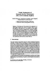
open, obstacle-free path between two points in space and must ... We call this a virtual sensor because it has all the properties of ..... Line of Sight Participation - a) Given three participating robots, we want to h d the places in the map where at least two .... Intsmntiooal Conference m Field and SsMsc Robotics, Pittsburgh, PA,.
!
Proeaedlngs ofthe 2004 IEEE intsmationd Conknnce on Robotics 6 AYtomatlon New Orleans, IA April 2004
Development and Deployment of a Line of Sight Virtual Sensor for Heterogeneous Teams Robert Grabowski, Pradeep Khosla and Howie Choset C A e g i e Mellon University Electrical and Computer Engineering, and Mechanical Engineering D e p m e n t Pittsburgh, Pennsylvania 15213 {grabowski, pkk, choset)@cs.cmn.edu
Absnact - For a learn of cooperaring robots, geometry plays a vital role in operalbm Knowledge of line of sight to local obstacles and a#acrnt teammales is critic01 in both the movemenr and planning stages to avoid collisions, maintain formation and I o d i z e the team. Howevrr, determining gother robots are within the line of sight of one another is diflcult with existing sensorplatforms especially as the scale of the robot is reduced We describe a method of exploiting collective team information to generate a vidual sensor that provides line of sight determination, greater range and resolution and the abilit, to generalize local sensing. We develop this sensor and apply it to the control of a tightly coupled, resourcelimited robot kam called Millibots.
Keywords4ompooent; heterogeneous control I.
mobile
robot
teams:
sensing;
INTRODUCTION
Robots are versatile machines that can be programmed to react collectively to sensor information in a variety of tasks that range from surveillance and reconnaissance to rescue support. Despite this versatility, a single robot cannot always realize all applications. On the other hand, a team of robots can coordinate action and sensing to extend a collection of individual entities to a single, cohesive group. To facilitate this coordination, a robot team must be able to manage its formation to exchange information and leverage the proximity of the others.
Figure 1. The Millibot Team - a heterogeneous collection of small-scale robots desieoed on the 5cm scale.
07803-8232-3/04/$17.00 02004 IEEE
Formation control is essential in many aspects of team coordination from communications [1][2] to sensor coverage [7][11] to localization [4][9][12]. A critical component of formation control is line of sight. Line-of-sight is d e h e d as an open, obstacle-free path between two points in space and must be wide enough to allow the passage of information signals such as light, video or ultrasonics. Unfortunately, local sensing is not always sufficient to directly determine the property of line of sight. Local sensors are often limited in their range and resolution and are incapable of discriminating between robot and obstacle. Even when a robot has access to a local map, it still may not have acquired sufficient information to make the determination on its om. This is especially true as the scale of the robot is decreased, the number of available sensors is restricted and the range of local sensing is reduced Coordinating multiple robots is a management issue as well. Conventional formation conIxol is based on the idea that each robot is equipped with roughly the same sensing capabilities. Heterogeneous team control must take into account for the differences in the sensing and processing capabilities of each robot. In some cases, tbis sensing may be rudimentary and not able to provide the necessary local information needed to navigate on its own [7][11]. The problem becomes even more compounded when the composition and number of the team is dynamic.
Our work is primarily motivated by the control and coordination of a team of heterogeneous, resource-lited robots, called Millibots [7J These are small-scale robots on the order of 5cm a side that are designed to operate in unlmown or partially known environments. Their small sue gives them access to tight, inaccessible areas while making them easier to conceal, deploy and manage. However, their small scale and dynamic heterogeneous composition makes conventional control strategies difficult to apply. We address coordination of multiple, heterogeneous robots by developing the concept of a ‘virtual’ sensor. Robot teams have the advantage that they can collectively share information. They are able to fuse range information from a variety of different platforms to build a global occupancy map that represent a single cotlective view of the environment. A virtual sensor is simply an abstraction of the team’s occupancy map. We call this a virtual sensor because it has all the properties of a real sensor with respect to that robot’s navigation and planning but is derived from information already processed and not from the physical interaction of a sensor and its
3024
sensing modalities.
surroundmgs. However, when employed by the individual, the information derived from a virtual sensor can be treated in the same fashion as a real sensor.
In Section 111, we develop the virtual sensor and show how it can provide essential line of sight information to obstacles, open space and other robots regardless of the platform being employed. In section IV,we show how this generalization aids in local, sensor-based planning by providing information witb greater range and resolution than existing local sensors. We then show how it can be extended to the planning stage with respect to maintaining line of sight to multiple members during and afier movement. Finally, in Section V, we show how the virtual sensor allows the generalization of existing sensors in such a way as to allow homogenous control laws to be applied to a heterogeneous team. 11.
RELATEDWORK
The concept of recasting local ,sensing is not new. Borenstein proposed recasting a robot's local map in terms of a polar sensor in the development of his Vector Field Histogram [SI. From the vector field, be is able to apply potential field methods for avoiding obstacles and navigating through open space. This method was designed primarily to support local, sensor-based navigation of a single robot and was not intended to support multiple robots. Banos utilizes a high-resolution laser range sensor to express the robot's cenkic view as a collection of polylines by connecting the ends of eacb range measurement together into a contour [3]. As the robot generates new views, he combines polylines to fonn a composite representation of the environment. While a powerful geometrical means for combining robot news, this method lacks a means for separating other robots from the environment as well as a means for assessing new plans based on the line of sight to other robots. Moreover, it relies on high resolution sensing which becomes problematic for robot teams with more limited
Nelson descrihes the generation of an enhanced range sensor by utilizing vision to evaluate the height information in a video image [IO]. The relationship between range and image height is made possible by regulating the dimensions of the walls in the environment. Moreover, line of sight to other robots is obtained by assigning unique colors to each robot. While this method solves both the range and line of sight issue, it requires the construction of a controlled environment and is not suitable for applications in unknown environments. 111.
THEVIRTUAL SENSOR
To develop the vimal sensor, we fust recast the team occupancy map as a polar occupancy map with respect to robot The polar map is constructed as a grid with the columns representing range and the rows representing bearing (Figure 2h). We make the transformation by mapping the value of the occupancy map cells to the corresponding polar occupancy cells for each cell in the polar map. From the polar map, we generate a polar contour that records the closest features in the map with respect to the center of the robot. Features captured by the polar contour include the closest obstacle and the closest free space boundary. The polar contour is stored as a single linear anay with the number of cells equal to the column width of polar map (Figure Zc). The indices of anay correspond to the angle and their values are the range to the closest feature This reduced representation allows rapid calculation of line of sight as well as a compact representation for faster communications.
To determine the range to the closest features, we scan each of the columns of the polar map 60m bottom (closest to the robot) to the top (maximum range) until we detect a cell that transitions from open (low occupancy) to either closed (high occupancy) or unexplored. If a transition from open to high occupancy is detected, the scan is terminated and the range is
obitack Twical Range Sensor
Polar 0Cr"Pa"q Map
Figure 2. Generating the Virtual Sensor. - a) A robot's local sensors may not have the resolution to determine line of sight to other members (darkgray profile) b) First step is to map the team's occupancy map into the individual polar map with the target robot at the center - axes are range and bearing. c) We process the polar map to generate a polar contour - For a given bearing, we mark the closest transition from open space to form obstacle contours and fiontier boundaries. Additionally, we project the profile of adjacent teammates onto the map d) We test each point in space against the contour map. All points within this region are within line of sight of the target robot. e) We utilize the values of a contour map to generate a virmal range sensor with greater m g e and resolution of the robot's individual sensor. This generalized profileis the same for any robot regardless of underlying sensor platform.
3025
adequately resolved due to lack of participation after such a move, the team may select an alternative move or opt to reposition others first.
recorded io the array. These cells represent the closest :obstacle points within the l i e of sight of the robot.
If a transition from open to unexplored is detected, the range to this feature is recorded. This transition represents the closest frootier point for that given angle. A frontier represents the boundary between known and unknown space and is used to guide exploration. To allow the storage of range information to two classes of features (frontier and obstacle points) in a single array, we store frootier points as negative values.
A. Local Planning Researcbers are already exploiting the increased resolutioo of maps generated by fusing multiple robot sensors to aid in exploration and localization. However, this has traditionally been a one-way process. Few are exploiting this map information to augment an individual robot’s perspective. consequently, each robot is left to develop plans based primarily 00 local sensors. We approach information exchange from the other perspective. That is, we use the higher fidelity of the team map to suppoTt sensing and local planning.
The polar contour stores the distance to the closest features withim a robot’s line of sight. However, its power comes from the ability to test line of sight to arbitrary points io $ace. We can readily establish whether a point in space is withi! line of sight of the robot by deteening the angle and range to the point with respect to the robot. If the point is above the contour (range greater for a given bearing) it is beyond that robot’s line of sight If it is below the contour it is withinline of sight.
In addition to line of sight determination, we can recast the virtual sensor in the form of an extended range sensor to aid in local robot planning. To accomplish this, we utilize the range values of a robot’s polar contour ai an element of a virtual sensor array (an imaginary range sensor) (Figure 2e). The angular and range resolution of the virtual sensor is a product of the number of rows and columns of the polar map and not the underlying sensor. Consequently, the range and resolution of the virtual sensor is generally greater than the underlying robot sensor.
Ironically, while robot range sensors, such as sonar, are good at detecting the distance to local obstacles, there are some , cases where they are unable to detect the presence ,of other .robois even when they afe within range. Such is the case,of the Millibots where the-sonar sensor platforms are mounted on . top of the robot. n e s e platfonns present a small cross section (effective reflection area of the robot) to ullmsonic bursts and consequently do not always reflect sufficient en,ergy to be detected. However, we can leverage team knowledge’ to account for undetected robots by artificially projecting their profile onto the polar contour. The positions of the robots are obtained from the tea& localition solutions and mapped into the polar map.
.
~
~
~- . . -.~
I&tead of simply treating these robots as a point source, we account for their size as well.-We~projectthese teamniatcs onto an individual robot’s polar map by generating a line. whose width is a function of the sue of .the actual robot, and the distance h m the center of the target robot. Figure 2c shows the projection of team members onto the target robot’s contour . map.~wherethe robot’s projection is closer than any other . feature, it replaces that feature as the closest point. ,Now the team can move reliably even when it cannot directly ‘detectits neighbors. Moreover, we have a method for determining the reliability of line of sight information, That is, we can assess .. whether a participating robot is partially obscured. This ability to account for the projected width of a robot (as opposed to a : point source) is one.of the advantages of utilizing a polar . . . contour over determining line of sight .by using simple ray . . tracing techniques. . * - .
.~
_-
:
~
~
-
w.
VIR~ALSENSORPLANNINO
Line of sight is not just a de6ction.issue; it must be considered during planning. Not only does a robot oeed’to know-which robots are within line of sight and which .are not, it needs to make the same assessment for futun5 cases in the planning stage. We can exploit the virmal sensor to aid in local robot planning as well as coordinated team planping. For example, localization effectiveness is often a,property of the number of robots that participate. Therefore, planning must also account for the number of robots that will be withim line of sight after the robot moves: If the new position cannot be
One immediate advantage to this formulation is the ability to perform local sensor-based planning. With greater resolution provided by the virtual sensor, a robot is able to generate finer resolution plans than possible with its original sensors. Many techniques exist that allow a robot to reliably navigate through h o r n spaces u t i l i n g only local sensors [3][5][6]. However, the success of these m&.ods is partially a function of theresolving ability of the sensors. For example, many robots have the luxury of supporting a high- resolution^ laser rangefinder or an array of 16 or more Polaroid sonar sensors. However-the typical Millibot sensor arky utilizes only 8 sonar range sensors each with a range of 30cm. Consequently; it has a harder time applying local control laws to maintain a path or follow the contour of local obstacles. 00 the other hand, a Virmal sensor has a derived range and resolution based on the resolution of the polar map and not the underlying sensor. Consequently, it can augment existing sensing to produce better motion plan8 for movement through the space. Robots also utilize features, such as obstacle profiles and frootiers, extracted h m the virmal sensor to navigate. One popular method in robot exploration is frontier expansion where the robot is duected towards existing boundaries between open and unexplored.space. However, it has been shown that specular reflection and general sensor failure can complicate the proper generation of itontiers IS]. Instead of directing the robot to viable search areas, specular reflection produces erroneous frontiers resulting in plans that duect the robot through obstacles. If the obstacle cannot be traversed, the attempt fails wasting valuable time and resources. On the other hand, a virtual sensor identifies obstacle boundaries and frontiers with respect to the position of an individual robot As such, it ignores potential erroneous information generated beyond the local line of sight of that robot. Consequently, it is not sensitive to the failures induced by specular reflection.
3c126
Obstacle profiles and 6ontier boundaries are exhacted *om the virtual sensor by clustering similar points along the polar contour into contiguous objects. Adjacent cells of positive values from the polar contour represent the profiles of obstacles while adjacent cells of negative values represent the profiles of fiontiers. Consequently, exploration can be accomplished by directing the robot towards the center of clustered hntier points. B. Line of Sight Participation Plonning Local control laws are useful for many aspects of robot navigation and planning. However, sometimes a robot has to coordinate its movements with respect to others in order to operate effectively. For example, Millibot requires that at least two other robots be within line of sight after any given move to generate a reliable position estimate. Before a Millibot moves to a new position, it must first assess its chances at localizing. To support this planning, we first examine the line of sight region generated by a single robot. These are all the points directly viewable with respect to that robot (Figure 2d). Now, if we view the same line of sight region &om the perspective of another robot, we have a way of predicting future line of sight constraints for the moving robot. Viewed in such a way, one robot’s line of sight region represents all the places a second robot can move and still maintain a connection with the first. The same process can be applied to each of the robots in the team. Consider the scenario given in Figure 3. Four robots have mapped a given space and have localized into the positions shown (Figure 3a). We now wish to move the robot under test to a new area in order to explore or provide mission specific
sensing. The three remaining robots, denoted Ra, Rb, Rc, remain stationary to support localizing the robot after the move. For localition to be successll, the moved robot bas to obtain valid range information 6om at least two of the other robots. The question is where can that robot move and still be in line of sight with respect to the remaining robots. Again we answer this question by utilizing the virmal sensors of each of the stationary robots. Figure 3b shows the virtual sensor generated by each of these robots and their corresponding line of sight regions. Each reading provides local information about whether the new position will be within its line of sight (Figure 3c). However, we get a composite assessment by projecting each of these regions simultaneously onto a common map (Figure 3d). Points where the regions overlap once represent common areas that are within the line of sight of at least two robots. Regions that overlap twice represent places where all three robots will be within line of sight of the new position. Assessing regions in terms of multiple overlaps provides a basis for coordinating multiple robots. The same procedure can be applied for any operation that requires a robot to maintain line of sight to one or more robots including localization, communications or surveillance. In practice, every point in space does not have to be evaluated as in the way illushated in Figure 3. Instead candidate movement points can be generated and evaluated by some other criteria.
C. Combining with a Locoluotion Mehic Line of sight and the number of participants is not the only factor in achieving good localization. The geometry of the formation is also a critical factor. Some formations naturally
Polar (a) Cwent Robot Map
@) Maps
Line of
1‘
sight
‘dl
Regions of Multiple L i e of Sight
Figure 3. Line of Sight Participation - a) Given three participating robots, we want to h d the places in the map where at least two are within line of sight. b) Each participating robot generates a polar plot by generating local polar map. c) Line of sight projected for each pdcipating robot. d) Combme line of sight projections - the darker the overlay, the greater the number of participants. The robot under test can move anywhere within the shown projections and still be in line of sight of at least two robots.
3027
..., .,.
-.
PmrLotWh
.
BeUO.rLnFJUUk,O
ToporeMuriaiatioo
Figure 4. Localization Meeic :a) Localization is poor when the
team geomeny approaches collinear.h) Localization is hkt when the angle between the two readings form a right angle. c) A metric plot showing utility of maximizing the angle bchveen the tangents of intersecting measuremenb Lights areas kprFent -
regionsin space that generate better localizationreadings. lend themselves to better position estimation @an others. For example, in a three-robot system, resolution of a third robot is best if we maximize the angles between range measurenlent pairs of the participating robots. In localization, range measurement.pairs can be visualized as an annulus with a center at the originating robot and a d i u s equal to the range measurement hetween the tivo robots. In a three-robot system, . two range pairs are obtained to localize that robot For the best localization, we maximize the'angle between the tangents of the two intersecting range pairs so that their combined distributions lie in a confined region of space. If the placement of the third robot is poorly selected (for example if the three . robots are collinear) the position estimate of the robot is also .' poor and spread over a large region of space (Figure 4a). . . However, if we maximize the angle between the tangents of the : range measurements (Figure e),the same combined 'distribution is eonfined to a smaller region 6 space resulting in . . a better position estimate. , -,~ Given this, howledge: we'can-utilize geometry in the . planning stage to guide robot movement as to best satisfy its line of sight conspaints while taking into account the best . . location €or e i n g its position estimate; To accomplish this, we develop a metric that maximizes the fangents of the, range pairs. Figure 4c shows the application of this metric to the space around the-set of robots. The lighter mas represent , regions in space tbat geueratewell-localized position istitnates while .the darker areas generate poor estimates. Coupled with the liie-of-sight assessment, candidates are selected that maximize localizatian resolution while enswing an adequate number of robots remains witbin line-of-sight of each'other. . A similar approach is &plied to deaf with the multitude of team constraints. For example, in the control of the Millibots, we cast a series of &dam p i n t s about a robot and pose each pomt as a candidate position for movement. From the list of candidates,. we tea each against conflicting constisints that include line of sight, .obstacle cleagmc_e, travel' distance, : exploration gain etc. The point witb the highest overall utili$ is . then selected and the rotiot is directedto that point. ~
team where the scale of the robots does not suppott a single robot type. Robots must distribute and coordinate sensing to achieve the necessary degree of perccption. For example, some robots ate equipped with sonar sensors that provide range infannation to obstacles while othm are equipped with ~ ~ S S ~ dependent O O sensing l i e heat detectors or video cameras. Conventional team control is accomplishedby treating each robot as if they were interchangeable. Control is a matter of managing the physical locations of the robots but not the individual resources of those robots. Heterogeneous composition complicates this methodology and inb.oduces complexity in the control process. Uniformity of sensing on an individual robot is an issue as well. Local navigation strategies ofieu assume a uniform sensor distn'bution about the robot. However, in some cases, a robot is quipped witb a variety of sensors each with different sensing characteristics. One example is the Dimbot (Figure Sa). This Millibot contains three fomard-lookinp sonars similar to others in the group each-with a range of 3 h . However, it gets its name &om two side-looking, digital infrared range sensors (dim). These sensors have a range of 80cm but a narrow 5degree field of view. Not only is the seasor profile for this robot nonuniform, it does not fully cover the area about the robot. Integrating this robot requires specialized routines far almost every aspect of operation. On the other band avirtnal sensor is posed as a unifonn array with respect to the robot (Figure 5c). Moreover, since the vimal sensor for each robot is derived fiom the fusion of the same team map, each robot can utilize the same navigation strategies.
,
V. HETEROGENEOUS SENSING As if reduced range 8ad resolution were not enough of a handicap, Some robot tw must contend with the composition of heterogeneous sensing. Such is the case for the Millihot L
3028
Figure 5. Supporting Heterogeneous Sensing - a) A heterogeneous Mllibot equipped witb f o d - l o o k i n g sonar and side-looking inked. b) Correlation between local and virmal sensor. c) Comparison of non-uuifonn local s-or and uniform virmal m s sensor.
Sensor failure also complicates reliable local navigation. Sensor failure and specular reflection often result in readings that indicate a clear path even when the path is obsbxcted. However, if we correlate the cument sensor readings with the derived virtual sensor readings (Figure Sb), we have a means for putting local readings in context and rejecting suspect readings. This additional confidence in sensing equates directly to competence in moving tbough a desired space without incident.
application of conventional homogenous control techniques on heterogeneous teams. REFERENCES
Andenon, S., Simmom, R, Goldberg, D., ‘‘Maintaining h e of Sight Commonications Networks between PLveuuy Rovm,” Roceedings of the 2003 IEEEJRSJ loll. Conference on Intellgent Robots and Systems Las Vegas, Nevada ’ O e t h 2003. Arkin, R, Balch, T., “Liabof-Sight Conspdined Exploration for Reactive Multiagent Robotic Team”, 7th International Workshop on Advanced Motion Conhul, AMC’OZ ,Maribor, Slovenia, July 2002. Banos, H., Mao, E., Latombe, J.C., Murali, T.M., and Efrat A. ‘?pluming Robot Motion Strategies for Efficient Model C o n m d o n . ” Robotics Research - The 9th Inl. Symposilrm, J.M. Hollerbach and D.E. Koditrchek (eds.), Springer, pp. 345-352.2000. Bissoo, I., Michaud, F., L&wmeau, D., “Relative Positioning ofMobileRobots Using Ultrasonics,” Rocsedbgs of the 2003 IEEEiRSJ Inll. C d e r e n c e on Intelligent Robots and Systems Las Vegar, Nevada .
In some cases, a robot simply does not have a means for sensing its own surroundings. One example is a Millibot equipped with only a video camera and localization beacon. Even when the robot needs to navigate in known space, it has no means for generating local plans without involving the operator. However, by utilizing the virtual sensor, the same robot can operate as if equipped with range sensors.
Virtual sensors provide an added benefit in that they allow the possibility of the generalization of local sensor platforms into a ubiquitous representation. Robots with long-range and short-range sensors generate similar virtual sensors as do robots with non-uniform sensor distribution or no sensors at all. This ability to generalize robot sensing is insbxmental in applying generalized robotic algorithms to heterogeneous robot platforms. VI. CONCLUSION In this paper we have shown how to generate a virtual sensor for each robot that is an abstraction of an individual robots sensor and the team’s occupancy map. The formulation of this sensor allows a local determination of line of sight local obstacles and kontiers as well as other robots in the team. This assessment is critical for establishing formation to support many aspects of team coordination including localization, communications and coverage. Equally important is the ability of determining when line of sight has been violated to reject potentially erroneous signals still present due to multipath reflections. Line of sight assessment is facilitated by expressing the range and hearing to local features in the form of a polar contour. Line of sight to arbihary points in space is determined by testmg whether the desired point lies above or below this contour.
October 2003. Borenptein, J., and b r e q Y. “The Vector Field Histogam - f s t Obsta~bAvoidance for Mobile Robots,” IEEE Transactions on Robotics and Automation 7(3): 278 -288. 1991 Chmet, H., Nagatani, IC, ‘Topological Simulfanmus Localation and Mapping (SLAM): Toward Exact Localization Without Explicit Localiutioq” In IEEE Transactions on Robotics and Automation, Vol. 17,No.Z,Apd,2001,pp. 125- 137. Grabowski, R, N a v m S e r m e n t . L. E., Paredis, C.J.J., and Wasla, P. “Hnerogenmus Teams of Modular Robots for Mapping and Exploration,” Autonomous Robots - Special Issue on Heterogeneous Multirobot Systems. Grabowski, R., Kborla, P.. Chosel, H., ”Autonomous Exploration via Regionr of Int-1,” Proceedings of the 2003 IEEEiRSJ Intl. Conference OIL Intelligent Robots and Systems I+ Vegas, Nevada . October 2003. N a v m , L., Paredis, C., Khmla P., “A Beacon System for the Localization of Distributed Robotic Teams,” in Proceedings of the Intsmntiooal Conference m Field and SsMsc Robotics, Pittsburgh, PA, August 29-31,1999. [IO] Neho4 A, Orant. E., Barlow, G., and Hendmon, T., “A Colony of Robots Using Vision Sensing and Evolved Nurml ConImIlm:’ Proceedings of the 2W3 E E E R S J Intl. Conference on Intelligent Robots and Systems Las Vega, Nevada. Octoba 2003. [ I l l Parker, L., Kanoan, B.,Fu, X., and Tang, Y.. “Heterogeneous Mobile Sensor Net Deployment Using Robot Hading and Lbe-of-Sight Pmeediagr ofthc 2003 IEEEfRSJ Inti. Conference on Formations,” Intelligent Robots and Systems l a p Vega, Neva$. October 2003. [I21 Rekleitis, Y.,Dud&, G., Milios, E., ‘Multi-Robot Collaboration for Robust Exploration,” Anoalr of Mathematics and Artificial Intelligence, 2001,volume31.N0. I-I,pp.740.
The utility of the virtual sensor moves from sensing to planning by viewing the contour of one robot with respect to the all the others. In this fashion, one robot’s line of sight region represents all the areas a second robot can move and still remain within the line of sight of the first. The same process can be simultaneously applied to the other robots in the team to satisfy formations that require line of sight to multiple robots. Finally we show the added utility of vimal sensing when applied to teams with heterogeneous sensor composition. m e virtual sensor provides a means of recasting a robot’s local sensing in terms of the collective sensing stored in the team’s occupancy map. Consequently, the derived virtual sensor is the same for any robot regardless of the underlying sensor platform. This ubiquitous representation of sensing allows the
3029
:
..