Hindawi Publishing Corporation International Journal of Distributed Sensor Networks Volume 2013, Article ID 168078, 7 pages http://dx.doi.org/10.1155/2013/168078
Research Article Development and Functional Evaluation of an Upper Extremity Rehabilitation System Based on Inertial Sensors and Virtual Reality Je-Nam Kim,1 Mun-Ho Ryu,2,3 Ho-Rim Choi,1 Yoon-Seok Yang,2,3 and Tae-Koon Kim4 1
Department of Healthcare Engineering, Chonbuk National University, 567 Baekje-daero, Deokjin-gu, Jeonju-si, Jeollabuk-do 561-756, Republic of Korea 2 Division of Biomedical Engineering, Chonbuk National University, 567 Baekje-daero, Deokjin-gu, Jeonju-si, Jeollabuk-do 561-756, Republic of Korea 3 Center for Healthcare Technology Development, Chonbuk National University, 567 Baekje-daero, Deokjin-gu, Jeonju-si, Jeollabuk-do 561-756, Republic of Korea 4 Medical Supply Co., Ltd., 1647-3, Donghwa-ri, Munmak-eup, Wonju-si, Gangwon-do, Republic of Korea Correspondence should be addressed to Mun-Ho Ryu;
[email protected] Received 21 March 2013; Revised 3 July 2013; Accepted 3 July 2013 Academic Editor: Tai-hoon Kim Copyright © 2013 Je-Nam Kim et al. This is an open access article distributed under the Creative Commons Attribution License, which permits unrestricted use, distribution, and reproduction in any medium, provided the original work is properly cited. An extremity rehabilitation program was proposed based on inertial measurement units (IMU) and virtual reality. A single IMU consists of a three-axis accelerometer, gyroscope, and geomagnetic sensors. One IMU is attached to the upper arm (master) and another to the forearm (slave). The IMUs are connected using a distributed sensor network implemented with interintegrated circuit communication. The motion-tracking algorithm running on a PC tracks the subject’s hand based on the estimated IMU orientation and segment lengths through forward kinematics. The training contents, including various dynamic movements and static holds, were designed to evaluate the spatiotemporal aspects of the subject’s functionality. The system was tested on a group of healthy subjects and a group with a simulated stiff elbow, allowing the evaluations to be quantitatively differentiated. The stiff elbow was simulated by taping the elbow to restrict the range of elbow motion. We expect the patients to be able to assess their own status without assistance from a therapist and select appropriate training methods to increase their rehabilitation effectiveness. Future studies will verify the availability and reliability of the upper extremity rehabilitation program for patients with a hemiplegia, leading to the development of an upper extremity rehabilitation program for three-dimensional movements of the upper extremities.
1. Introduction A stroke, which is a type of cerebrovascular condition, is the third-highest cause of death in the United States [1]. Although stroke patients often regain consciousness after onset, 30– 40% of patients suffer from hemiplegic complications such as a speech disorder or dementia, impeding their ability to live a normal life. Among the various disorders caused by a stroke, hemiplegia is very typical, with more than 80% of stroke patients displaying some form of hemiplegic disability [2]. The restoration of the upper extremity functionality is slow compared to the recovery of other functions such as posture or gait. Furthermore, if the rehabilitation is
discontinued, patients may be unable to regain their normal upper extremity ability [1]. This poses a problem when cost and/or space limitations reduce the amount of rehabilitation training that patients can receive at a hospital. After discharge, patients must undertake rehabilitation at home [3]. Without the direction of a physical therapist, such patients may be unable to determine their own status or select an appropriate rehabilitation program. In addition, traditional devices for upper extremity rehabilitation are simple and tedious to use, and patients may lose interest in them over the long term. If a patient does not engage in rehabilitation for the recommended time period, the efficiency of the process may decrease. To overcome this
2
International Journal of Distributed Sensor Networks
limitation, many studies have focused on a variety of training, confirming the results through a virtual reality system. Several studies using commercial gaming devices such as the Nintendo Wii or Microsoft’s XBOX360 Kinect sensor have shown a clinical effect [4–6]. However, these systems do not evaluate the patient’s functionality during training, which is necessary for patients to conduct rehabilitation at home on their own. Zhang et al. [7] attached an inertial sensor to the wrist and elbow joints of different patients and provided therapists with tools to remotely observe the rehabilitation movements of their patients in real time. The therapists were then able to design an appropriate exercise program according to the training progress of their patients. This system includes only three types of actions, that is, arm stretching, bending, and drinking water. Similarly, Willmann et al. [1] used a system that tracks the behavior of the upper extremity using inertial sensors. A physical therapist confirms the condition of the patient at a hospital directly or indirectly based on an examination of the stored data and then presents the next movement that the patient should practice. However, this system does not provide a systematic exercise method because it is dependent on the feedback of the physical therapist. We previously presented an upper extremity rehabilitation system based on commercial motion tracking and virtual reality [8]. In the present study, we highlight the development of a motion-tracking system based on the use of inertial sensors and a distributed sensor network and show the functional feasibility of the rehabilitation system. This motion-tracking system consists of two inertial sensors attached to the upper limb of the subject and a motiontracking algorithm running on a PC. The inertial sensor consists of a three-axis microelectromechanical system (MEMS) accelerometer, a gyroscope, and geomagnetic sensors. The sensor data are transmitted wirelessly to a PC, where the orientation and position of the subject are tracked. Virtual reality using the OpenGL library (http://www.opengl.org/) is implemented on the PC to provide rehabilitation movements and assess the upper extremity functionality of the subject. The system can be used at home without the assistance of a therapist. To verify the functional feasibility, this system was applied to healthy subjects and to subjects with a simulated stiff elbow condition. The stiffness was simulated by taping the elbow, which restricted its range of motion.
orientation and segmental length. The rehabilitation content, which also runs on the PC, provides the trajectory of the upper limb using a graphic library and evaluates the subject’s real trajectory. Each IMU (17.8 mm × 13.0 mm) is composed of a microcontrol unit (MCU), microelectromechanical system (MEMS) inertial sensors, and a Bluetooth communication module (Figure 2(a)). A three-axis accelerometer/magnetometer (LSM303DLHM, STMicroelectronics) and a threeaxis gyroscope (L3GD20, STMicroelectronics) were used as the inertial sensors. The gyroscope was set to a full scale of ±500∘ /s and a sampling rate of 100 Hz. The MCU (STM32F103C8, STMicroelectronics) reads the sensors using interintegrated circuit (I2C) communication. The master and slave IMUs were attached to the upper arm and forearm of the subject, respectively. The communication between the master and slave IMUs was conducted using a distributed sensor network implemented based on another I2C communication. The I2C master and slave protocols were programmed in the master and slave IMUs, respectively. The MCU in the master IMU reads the sensor data of the slave IMU through I2C communication and sends the master and slave data packets using a Bluetooth module (Parani ESD200, Sena Technology, Korea) to the PC.
2. System Overview
3. Motion-Tracking Algorithm
The proposed system consists of a motion tracker and rehabilitation content (Figure 1). The motion tracker consists of two inertial measurement units (IMU) attached to segments of the subject’s upper limb and a motion-tracking algorithm running on a PC. The IMUs are connected with a proprietary distributed sensor network. One IMU collects the sensor data of the other IMU and transmits both sensor data packets wirelessly to the PC. The motion-tracking algorithm on the PC receives the data packets, estimates the orientations of the IMSs from the sensor data, and finally calculates the segment positions of the subject along with the estimated
The transmitted data packet is processed using the motiontracking algorithm on the PC to estimate the IMU’s orientation. This orientation is expressed as a rotation matrix, S2G 𝑅, from the global frame to the sensor frame, which is calculated by integrating the gyroscope’s angular velocity signal, 𝜔 = [𝜔𝑥 𝜔𝑦 𝜔𝑧 ]𝑇 [9]:
IMU
Data packet handling
Rehabilitation contents
IMU
Orientation estimation
OpenGL graphics
Position calculation
Rehabilitation evaluation
Motion-tracking algorithm
Rehabilitation contents
IMUs
Figure 1: System overview. The two IMUs and the motion-tracking algorithm utilize a motion tracker. The motion-tracking algorithm and rehabilitation content are implemented on a PC.
Δ𝑅𝑘S2G = 𝐼 +
1 − cos 𝜎 sin 𝜎 [𝜎×] + [𝜎×]2 , 𝜎 𝜎2
S2G = 𝑅𝑘S2G + Δ𝑅𝑘S2G , 𝑅𝑘+1
(1) (2)
International Journal of Distributed Sensor Networks
3
Yaw
Roll
Pitch (a)
(b)
Figure 2: Inertial measurement unit (IMU): (a) sensor board and its direction and the (b) slave (left) and master (right) IMUs.
where
yG
∫
Prediction
𝑇
𝜎 = 𝜔 ⋅ Δ𝑡= [𝜎𝑥 𝜎𝑥 𝜎𝑥 ] , 0 −𝜔𝑧 𝜔𝑦 0 −𝜔𝑥 ] . [𝜎×] = [ 𝜔𝑧 −𝜔 𝜔 0 ] 𝑥 [ 𝑦
(3)
However, small offsets in the gyroscope signal accumulate during the integration, which is known as a drift problem. Drift is corrected by fusing the gravity and Earth’s magnetic field sensed using a Kalman filter [9, 10]. In particular, the system model for human-motion tracking is described well in [9]. For self-completeness, the orientation estimation can be summarized as follows (Figure 3). The accelerometer, gyroscope, and magnetometer sensor signals (𝑦𝐴,𝑡 , 𝑦𝐺,𝑡 and 𝑦𝑀,𝑡 ) 𝑦𝐴,𝑡 are modeled as in (1): 𝑦𝐴,𝑡 = 𝑎𝑡 − 𝑔 + V𝐴,𝑡 , 𝑦𝐺,𝑡 = 𝜔𝑡 + 𝑏𝑡 + V𝐺,𝑡 ,
where 𝑎𝑡 , 𝜔𝑡 , and 𝑚𝑡 are the acceleration, gyroscope offset, and magnetic field, respectively; 𝑔, 𝑏𝑡 , and 𝑑𝑡 are gravity, the gyroscope offset, and magnetic disturbance; and V𝐴,𝑡 , V𝐺,𝑡 , and V𝑀,𝑡 represent white Gaussian measurement noises. The acceleration and magnetic disturbance are modeled into a Markov process model with white driving noise and a constant of between 0 and 1, as in
𝑑𝑡 = 𝑐𝑑 𝑑𝑡−1 + 𝑤𝑑,𝑡 .
Measurement
Correction
𝜃
Figure 3: Kalman filter structure. The gyroscope signal, 𝑦𝐺, is integrated to predict the sensor orientation. The predicted orientation is corrected with the accelerometer signal, 𝑦𝐴 , and magnetometer signal, 𝑦𝑀 .
[𝜃𝜖,𝑡 𝑏𝜖,𝑡 𝑑𝜖,𝑡 ]𝑇 , is estimated. The error state transition matrix is defined from the error dynamics, as in 𝐼3×3 03×3 −𝑇 ⋅ 𝐼3×3 𝐼3×3 ] . 𝐴 = [03×3 𝐼3×3 0 0 𝐼3×3 ] [ 3×3 3×3
(6)
(4)
𝑦𝑀,𝑡 = 𝑚𝑡 + 𝑑𝑡 + V𝑀,𝑡 ,
𝑎𝑡 = 𝑐𝑎 𝑎𝑡−1 + 𝑤𝑎,𝑡 ,
yA yM
After the error state is estimated, it is added to the state estimation. With an estimated orientation of 𝜃, included in the estimated state, the acceleration and magnetic signals in the global frame can be estimated. Since the estimated orientation has an error, these estimated signals also have an error. This estimated orientation is therefore corrected by comparing the estimated and measured signals with a measurement matrix, as in 𝐶=[
(5)
In this indirect Kalman filter, the error state including the orientation, gyroscope offset, and magnetic distortion, 𝑥𝜖,𝑡 =
−𝑍𝐺× 𝑇𝑍𝐺× 03×3 ], −𝐻𝐺× 𝑇𝐻𝐺× −𝑐𝑑 𝐼3×3
(7)
where 𝑍𝐺 and 𝐻𝐺 correspond to the vertical 𝑍 acceleration and magnetic field in the global frame calculated by integrating the gyroscope signal, respectively.
4
International Journal of Distributed Sensor Networks
(a)
(b)
Figure 4: Virtual-reality-based upper extremity rehabilitation program. A conceptual drawing (a) and the simplified version used in this study (b).
The error state covariance 𝑄 and measurement covariance 𝑅 matrixes are calculated as in 𝑇2 𝑄V𝐺 03×3 03×3 𝑄 = [ 03×3 𝑄𝑤𝑏 03×3 ] , [ 03×3 03×3 𝑄𝑤𝑑 ]
(8)
2
𝑇 𝑄V𝐺 + 𝑄V𝐴 03×3 𝑅=[ ], 03×3 𝑇2 𝑄V𝐺 + 𝑄V𝑀
𝑃upper = 𝑅G2U 𝐿 upper , G2U
𝑃fore = 𝑅G2F 𝑅
where 𝑄V𝐺 , 𝑄V𝐺 , and 𝑄V𝐺 are the measurement covariance matrixes of the gyroscope, accelerometer, and magnetometer. 𝑄V𝐺 and 𝑄V𝐺 correspond to the covariances of the gyroscope offset and magnetic disturbance. With these matrixes, the indirect Kalman filter estimates the current state from the previous state and state transition matrix 𝐴. The covariance of the estimated state error 𝑃 is also estimated as in (9). 𝑃𝑘+1|𝑘 indicates the covariance of the state error estimated at time 𝑘 + 1, based on that at previous time 𝑘: 𝑃𝑘+1|𝑘 = 𝐴 𝑘 𝑃𝑘|𝑘 𝐴𝑇𝑘 + 𝑄𝑘 .
(9)
Finally, the measurement is updated as in V𝑘+1 = 𝐶𝑘+1 𝑥𝑘+1 − 𝑧𝑘+1 , −1
𝑇 𝑇 𝐾𝑘+1 = 𝑃𝑘+1|𝑘 𝐶𝑘+1 (𝐶𝑘+1 𝑃𝑘+1|𝑘 𝐶𝑘+1 + 𝑅𝑘+1 ) ,
𝑥𝜀𝑘+1|𝑘 = 𝐾𝑘+1 V𝑘+1 ,
With the estimated orientations and predefined segmental lengths, the positions of the upper arm 𝑃upper and forearm 𝑃fore relative to the shoulder joint were calculated using the forward kinematics. For the upper arm, the position was calculated as in
(10)
𝑃𝑘+1|𝑘+1 = 𝐴 𝑘 𝑃𝑘+1|𝑘+1 𝐴𝑇𝑘+1 + 𝑄𝑘+1 , where 𝑧𝑘+1 is a measurement consisting of acceleration and magnetometer signals, and 𝐾𝑘+1 corresponds to the Kalman filter gain. These procedures from (1) to (10) are repeated when the sensor signals are received. They are programmed with MATLAB scripts and converted into 𝐶 files using a codegen tool (MATLAB7.12, Mathworks). The converted 𝐶 files are included and compiled as a PC application, which includes the motion-tracking algorithm and rehabilitation content. The execution time of the orientation algorithm with a Kalman filter was measured to be about 0.03 ms on a PC (3.0 GHz dual-core Pentium with 2.0 GB of RAM).
(11) 𝐿 fore + 𝐿 upper ,
where 𝑅G2U and 𝑅G2F are the rotations of the sensors in the upper arm and forearm, and 𝐿 upper and 𝐿 fore correspond to the measured segmental lengths of the upper arm and forearm, respectively.
4. Upper Extremity Rehabilitation Program The upper extremity rehabilitation application was programmed using Visual C++ 6.0 (Figure 4). The virtual reality platform used to express three-dimensional movement of the upper extremity and the two-dimensional upper extremity rehabilitation program were implemented using OpenGL. The rehabilitation content was designed to provide both training and evaluation at the same time. The content included various dynamic movements and static holds and provided them to the subject within the virtual environment (Figure 5). The dynamic movements consisted of various movements such as shoulder flexion, abduction, adduction, and elevation; elbow flexion and extension; and forearm pronation and supination. The evaluation algorithm was derived from well-established methods including the Upper Extremity Motion Score [11] and Fugl-Meyer Assessment Scale [12]. The static holds were designed to maintain the arm position for a certain period after stretching and lifting the arms and were evaluated based on the National Institutes of Health (NIH) Stroke Scale [13] and the European Stroke Scale [14]. Based on these rationales, the functionality of each subject was evaluated for its spatiotemporal aspects. The average positional difference (𝐷pos ) between the provided training trajectory and the hand position of the patient was calculated as 100 Hz. The average time duration (𝑇out ) was also accumulated when the positional difference was larger than a predefined threshold.
International Journal of Distributed Sensor Networks
3
5
3
2
4
2 1
4 1
1
5
5 8 6
8 6
7
(a)
2
7
(b)
(c)
Figure 5: Training content examples: (a) static hold, (b) linear movement, and (c) circular movement.
(a)
(b)
Figure 6: Subject conditions: (a) normal condition and (b) stiffness simulated by taping the elbow.
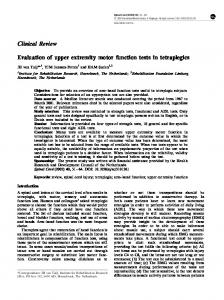
5. Feasibility Test To verify its functional feasibility, the system was applied to five healthy subjects (26–30 years old, all male). To simulate a stiff elbow, which is a poststroke complication, the elbow of each healthy subject was taped to restrict its range of motion (Figure 6). The figure shows the system configuration for both the normal group and the group with a simulated stiff elbow [15, 16]. The linear and circular movements were provided within the virtual environment. The subjects were asked to follow the provided trajectories as best they could. The linear movements were provided in eight directions (Figure 5(b)), whereas the circular movements were provided in the CW and CCW directions (Figure 5(c)). Each movement was repeated ten times for each subject. The values of 𝐷pos and 𝑇out were calculated and analyzed. Figure 7 shows the hand position trajectory for both the normal and stiff-elbow simulated groups. It was observed
that the trajectory under a simulated stiff-elbow condition was qualitatively rougher than the trajectory under normal conditions. Table 1 summarizes 𝐷pos and 𝑇out for the linear and circular movements. All 𝐷pos s and 𝑇out s values were merged over the subjects and movement types and compared using a paired 𝑡-test for the linear and circular movements of both groups, respectively. The values of 𝐷pos s and 𝑇out s showed significant differences between the normal and stiff-elbow simulated groups (all 𝑃 < 0.001 for linear 𝐷pos , linear 𝑇out , circular 𝐷pos , and circular 𝑇out ). This demonstrated the functional feasibility of the proposed system for evaluating the upper extremity function of a poststroke patient in a quantitative manner.
6. Conclusion In this study, an extremity rehabilitation program was proposed based on the use of IMUs and a virtual-reality system.
International Journal of Distributed Sensor Networks 50
50
40
40
30
30
20
20
10
10 y-axis
y-axis
6
0
0
−10
−10
−20
−20
−30
−30
−40
−40
−50 −50 −40 −30 −20 −10
0 10 x-axis
20
30
40
50
−50 −50 −40 −30 −20 −10
(a)
0 10 x-axis
20
30
40
50
(b)
Figure 7: Trajectory example: (a) linear and (b) circular movements. The black line, blue rectangles, and red circles correspond to the training trajectory provided, the tracked positions under normal conditions, and the tracked positions for the stiff-elbow simulated group, respectively.
Table 1: 𝐷pos s (cm) and 𝑇out s (s) for the two groups and movement type (cm): N, normal group; S, simulated stiff elbow group. group N S
𝑇out
𝐷pos
Linear movement
Circular movement
Linear movement
Circular movement
0.07 0.39
0.97 3.79
5.40 5.89
5.76 6.76
Acknowledgments This work was supported by the Technology Innovation Program (project no. SA113286) funded by the Small & Medium Business Administration (SMBA, Korea) and by the Basic Science Research Program through the National Research Foundation of Korea (NRF) funded by the Ministry of Education, Science and Technology (2013-026506).
References The IMUs were used to track the subject’s hand based on its calculated orientation and segment lengths with forward kinematics. In addition, the training content, including various dynamic movements and static holds, was designed to evaluate the spatiotemporal aspects of the subject’s functionality. To quantitatively differentiate the evaluations, the proposed system was tested on both a group of healthy subjects and a group of subjects with a simulated elbow stiffness achieved by taping the elbow. Using the upper extremity rehabilitation system developed in this study, we anticipate that patients will be able to undergo upper extremity rehabilitation on their own without the help of a therapist. Furthermore, a subsequent evaluation of the upper extremity function can be conducted by selecting an appropriate training program; this will increase the effectiveness of their rehabilitation. In future studies, the validity and reliability of upper extremity rehabilitation programs will be assessed for patients with a poststroke upper extremity hemiplegia. Three-dimensional upper extremity rehabilitation programs will be developed to ensure more accurate rehabilitation training for various upper extremity movements as displayed three dimensionally.
[1] R. D. Willmann, G. Lanfermann, P. Saini, A. Timmermans, J. Te Vrugt, and S. Winter, “Home stroke rehabilitation for the upper extremity,” in Proceedings of the 29th Annual International Conference of the IEEE Engineering in Medicine and Biology Society (EMBS ’07), pp. 4015–4018, August 2007. [2] V. M. Parker, D. T. Wade, and R. Langton Hewer, “Loss of arm function after stroke: measurement, frequency, and recovery,” International Rehabilitation Medicine, vol. 8, no. 2, pp. 69–73, 1986. [3] M. Kuttuva, R. Boian, A. Merians et al., “The Rutgers arm, a rehabilitation system in virtual reality: a pilot study,” Cyberpsychology and Behavior, vol. 9, no. 2, pp. 148–151, 2006. [4] M. R. Mouawad, C. G. Doust, M. D. Max, and P. A. McNulty, “Wii-based movement therapy to promote improved upper extremity function post-stroke: a pilot study,” Journal of Rehabilitation Medicine, vol. 43, no. 6, pp. 527–533, 2011. [5] B. Lange, C.-Y. Chang, E. Suma, B. Newman, A. S. Rizzo, and M. Bolas, “Development and evaluation of low cost game-based balance rehabilitation tool using the microsoft kinect sensor,” in Proceedings of the 33rd Annual International Conference of the IEEE Engineering in Medicine and Biology Society (EMBS ’11), pp. 1831–1834, August-September 2011. [6] I. Pastor, H. A. Hayes, and S. J. Bamberq, “A feasibility study of an upper limb rehabilitation system using kinect and computer
International Journal of Distributed Sensor Networks
[7]
[8]
[9] [10]
[11]
[12]
[13]
[14] [15]
[16]
games,” in Proceedings of the 34th Annual International Conference of the IEEE Engineering in Medicine and Biology Society (EMBS ’12), pp. 1286–1289, August-September 2012. S. Zhang, H. Hu, and H. Zhou, “An interactive Internet-based system for tracking upper limb motion in home-based rehabilitation,” Medical and Biological Engineering and Computing, vol. 46, no. 3, pp. 241–249, 2008. J. N. Kim, M. H. Ryu, Y. S. Yang, and T. K. Kim, “Upper extremity rehabilitation program using inertial sensors and virtual reality for patients with upper extremity hemiplegia due to disorders after stroke,” in Proceedings of International Conference on Computer Science and Technology (CST ’12), pp. 71–76, June 2012. P. S. MayBeck, Stochastic Models, Estimation, and Control, vol. 2, Academic Press, New York, NY, USA, 1982. D. Roetenberg, H. J. Luinge, C. T. M. Baten, and P. H. Veltink, “Compensation of magnetic disturbances improves inertial and magnetic sensing of human body segment orientation,” IEEE Transactions on Neural Systems and Rehabilitation Engineering, vol. 13, no. 3, pp. 395–405, 2005. G. Bard and G. G. Hirschberg, “Recovery of voluntary motion in upper extremity following hemiplegia,” Archives of Physical Medicine and Rehabilitation, vol. 46, pp. 567–572, 1965. A. R¨od´en-J¨ullig, M. Britton, C. Gustafsson, and A. Fugl-Meyer, “Validation of four scales for the acute stage of stroke,” Journal of Internal Medicine, vol. 236, no. 2, pp. 125–136, 1994. T. Brott, H. P. Adams Jr., C. P. Olinger et al., “Measurements of acute cerebral infarction: a clinical examination scale,” Stroke, vol. 20, no. 7, pp. 864–870, 1989. L. Hantson, W. de Weerdt, J. de Keyser et al., “The European stroke scale,” Stroke, vol. 25, no. 11, pp. 2215–2219, 1994. L. C. MacKean, G. Bell, and R. S. Burnham, “Prophylactic ankle bracing versus taping: effects on functional performance in female basketball players,” Journal of Orthopaedic & Sports Physical Therapy, vol. 22, no. 2, pp. 77–81, 1995. M. Patterson and B. Caulfield, “Using a shoe mounted triaxial accelerometer to detect kinematic changes during stiff ankle walking,” in Proceedings of the Annual International Conference of the IEEE Engineering in Medicine and Biology Society (EMBS ’11), pp. 3492–3495, August 2011.
7
International Journal of
Rotating Machinery
Engineering Journal of
Hindawi Publishing Corporation http://www.hindawi.com
Volume 2014
The Scientific World Journal Hindawi Publishing Corporation http://www.hindawi.com
Volume 2014
International Journal of
Distributed Sensor Networks
Journal of
Sensors Hindawi Publishing Corporation http://www.hindawi.com
Volume 2014
Hindawi Publishing Corporation http://www.hindawi.com
Volume 2014
Hindawi Publishing Corporation http://www.hindawi.com
Volume 2014
Journal of
Control Science and Engineering
Advances in
Civil Engineering Hindawi Publishing Corporation http://www.hindawi.com
Hindawi Publishing Corporation http://www.hindawi.com
Volume 2014
Volume 2014
Submit your manuscripts at http://www.hindawi.com Journal of
Journal of
Electrical and Computer Engineering
Robotics Hindawi Publishing Corporation http://www.hindawi.com
Hindawi Publishing Corporation http://www.hindawi.com
Volume 2014
Volume 2014
VLSI Design Advances in OptoElectronics
International Journal of
Navigation and Observation Hindawi Publishing Corporation http://www.hindawi.com
Volume 2014
Hindawi Publishing Corporation http://www.hindawi.com
Hindawi Publishing Corporation http://www.hindawi.com
Chemical Engineering Hindawi Publishing Corporation http://www.hindawi.com
Volume 2014
Volume 2014
Active and Passive Electronic Components
Antennas and Propagation Hindawi Publishing Corporation http://www.hindawi.com
Aerospace Engineering
Hindawi Publishing Corporation http://www.hindawi.com
Volume 2014
Hindawi Publishing Corporation http://www.hindawi.com
Volume 2014
Volume 2014
International Journal of
International Journal of
International Journal of
Modelling & Simulation in Engineering
Volume 2014
Hindawi Publishing Corporation http://www.hindawi.com
Volume 2014
Shock and Vibration Hindawi Publishing Corporation http://www.hindawi.com
Volume 2014
Advances in
Acoustics and Vibration Hindawi Publishing Corporation http://www.hindawi.com
Volume 2014