a dedicated mobile accelerator that protects organs at risk within the radiation field and conforms the beam to the target geometry during intraoperative electron ...
Development and optimization of a beam shaper device for a mobile dedicated IOERT accelerator Antonella Soriania) and Giuseppe Iaccarino Laboratory of Medical Physics and Expert Systems, National Cancer Institute Regina Elena, 00144 Rome, Italy
Giuseppe Felici and Alessia Ciccotelli Sordina S.p.A Technical Division, Rome 00126, Italy
Paola Pinnarò and Carolina Giordano Radiation Oncology Department, National Cancer Institute Regina Elena, 00144 Rome, Italy
Marcello Benassi Medical Physics Department, IRCCS Istituto Scientifico Romagnolo per lo Studio e la Cura dei tumori, 47014 Meldola, Italy
Marco D’Andrea, Luca Bellesi, and Lidia Strigari Laboratory of Medical Physics and Expert Systems, National Cancer Institute Regina Elena, 00144 Rome, Italy
(Received 29 February 2012; revised 20 August 2012; accepted for publication 20 August 2012; published 21 September 2012) Purpose: The aim of this study was to design and build a prototype beam shaper to be used on a dedicated mobile accelerator that protects organs at risk within the radiation field and conforms the beam to the target geometry during intraoperative electron radiotherapy (IOERT). A dosimetric characterization of the beam shaper device was performed based on Monte Carlo (MC) simulations, as well as experimental data, at different energies, field sizes, and source to skin distances. R , Sordina, Italy) was used. The design Methods: A mobile light intraoperative accelerator (LIAC� of the beam shaper prototype was based on MC simulations (BEAMnrc/OMEGA and DOSXYZnrc code) for a selection of materials and thicknesses, as well as for dosimetric characterization. Percentage depth dose (PDD) and profile measurements were performed using a p-type silicon diode and a commercial water phantom, while output factors were measured using a PinPoint ion chamber in a PMMA phantom. Planar doses in planes of interest were carried out using radiochromic films R phantom. Several experimental (GafchromicTM EBT and EBT2) in PMMA and in a Solid Water� set-ups were investigated with the beam shaper device fixed on the top of the phantom, varying both the short side of the rectangular field and the air gap between the device and the phantom surface, simulating the clinical situation. The output factors (OFs) were determined using different geometrical set-ups and energies. Results: The beam shaper prototype consists of four blades sliding alongside each other and mounted on a special support at the end of the 10 cm diameter PMMA circular applicator. Each blade is made R and a lower layer of 8 mm of stainless steel. All rectangles of an upper layer of 2.6 cm of Teflon� inscribed in a 5 cm diameter can be achieved in addition to any “squircle-shaped” field. When one side of the rectangular field is held constant and the second side is reduced, both R50 and Rmax move towards the phantom surface. Comparing the PDDs obtained with the 5 cm circular applicator and with a 4.4 × 4.4 cm2 square field (that is the equivalent square of the 5 cm circular field) obtained with the beam shaper, a different behavior was observed in the region extending from the surface to a depth of 50% of the maximum dose. Isodoses measured for rectangular fields used for clinical cases (i.e., 4 × 9 cm2 8 MeV) are shown, with different air gaps. For each energy investigated, the normalized OFs slowly increase, when the length of the side decreases down to about 4 cm, and then rapidly decreases for smaller field widths. MC simulation showed an excellent agreement with experimental data (5 cm), and margin-positive tumors, with improved local control being the main benefit of RT. IOERT is a unique modality that allows the sterilization of microscopic disease during surgery5–7 and the selective shielding of adjacent normal tissues, allowing high single doses of radiation to be delivered while sparing normal tissues. Thus, IOERT is well suited as an adjunct to resection of tumors in patients with recurrent and locally advanced malignancies. In sarcomas, targets usually have irregularly elongated shapes, with adjacent anatomical structures that have to be preserved. In the past, for conventional accelerators working in a bunker, squircle applicators have been developed which allow the abutting of fields without overlap.8 Unfortunately this type of applicator is not available for dedicated mobile accelerators. Janssen et al.3 built and tested a single rectangular R 8 × 15 cm2 applicator, specially designed for the Mobetron� (Intraop Medical Corporation, Sunnyvale, CA) IOERT accelerator. For other types of mobile accelerator, the current alternative is to overlap circular fields or match fields by using a straight piece of lead, introducing additional uncertainties and/or hot and cold dose points. It would be more convenient, particularly in the case of very large tumors, to use properly shaped rectangular fields to adapt them to the treatment area. Furthermore, up to now we have an applicator for each field and it would be preferable to have only one applicator with variable field to produce a set of rectangular fields. It is therefore of interest to develop a beam shaping device able to transform a circular beam with a diameter of 100 mm into a rectangular field, with continuous adjustment of field size, and appropriate attenuation outside the treatment field for all the available energies. Obviously, this device must be built using materials that are biocompatible, easy to sterilize Medical Physics, Vol. 39, No. 10, October 2012
6081
and must be versatile enough to be used on any surgical bed in any spatial orientation. The aim of this study was to design and build a prototype beam shaper, to be used on the mobile light intraoperative R ), which protects organs at risk (OARS ) accelerator (LIAC� within the radiation field and conforms the beam to the target geometry during IOERT. The second aim was to characterize this device from the dosimetric point of view, with the help of Monte Carlo (MC) simulations, in order to optimize the dose delivery. The third aim was to measure the output factors (OFs), percentage depth doses (PDDs), and profiles, at different energies, field sizes, and source to skin distances (SSDs). II. MATERIALS AND METHODS II.A. IOERT accelerator characteristics R LIAC� is a mobile accelerator, manufactured by Sordina, Italy, specifically designed to perform IOERT inside an unshielded operating room. This linear accelerator can only operate in the electron mode, with energies up to 12 MeV (corresponding to a R50 value of 45 mm). Beam collimation is achieved by means of cylindrical PMMA applicators of different sizes (30–100 mm), 60 cm long, with bevel angles of 0◦ , 15◦ , 30◦ , and 45◦ . By using a robotic arm, the unit has more degrees of freedom to align the electron beam applicator with the target in the patient than a conventional accelerator. This machine does not use a bending magnet and only a very thin aluminum scattering foil (850 μm) is used to flatR can work in almost any ten the field. Therefore, the LIAC� conventional operating room, while the need for temporary mobile shields or structural shielding for radiation protection purposes mainly depends on the annual workload and location characteristics.9 The BEAMnrc Monte Carlo code based on EGSnrc was R as reported in a separate paper.10 used to model the LIAC� Monte Carlo simulation was used for the dose distributions of all available energies and applicators and to verify the agreement with experimental measurements, and is a benchmark to develop and optimize the beam shaper prototype.
II.B. Prototyping a beam shaper device
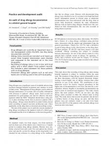
To shape the beam and obtain a rectangular field of irradiation, four blades are mounted on a special support sliding alongside each other and overlapping (Fig. 1), so that each other overlapping, so that there is no leakage between blades; this implies that the blades do not move independently, but the opposing blades move simultaneously. The center of the rectangle is always the center of the circle. Thus, it is feasible to conform fields with any rectangle/squircle within a 10 cm diameter. A “squircle” is a rounded square shape generated by arranging two or more parts of a circle and connecting their loose ends with straight lines. Taking a and b as the sides of the rectangle; if (a/2)2 + (b/2)2 > r2 the field obtained is no longer a rectangle but a squircle, r being the radius of the applicator, e.g., using a
6082
Soriani et al.: A beam shaper device for an IOERT accelerator
6082
R F IG . 1. (a) LIAC� beam shaper sketch with an example of two (b) upper and (c) lower beam eye views.
10 cm applicator (i.e., r = 5 cm), the 9 × 3 cm2 field is a rectangle, while the 9 × 7 cm2 field is a squircle. After choosing the desired configuration of the blades, they may be locked into place. The design of this collimator system strongly affects the dosimetric properties of the IOERT system and must be carefully studied. When building the prototype, materials had to be selected to produce a minimum of undesirable effects, such as bremsstrahlung radiation. These materials will be used to give the beam its desired shape. The most favorable configuration comprised a first upper layer of low Z material, polytetrafluoR , with roethylene (PTFE) known by the trade name of Teflon� a lower layer of high Z material, stainless steel (AISI 316 LN). This choice of materials guarantees that the device is biocompatible and can easily be sterilized. Regarding the mechanical aspects of the device, the beam shaper actually allows a simplified procedure of conformal IOERT. The beam shaper prototype is mounted at the end of the lower part of the applicator (30 cm length) and can be fixed to any operating table using a locking system that allows movement in any direction with four degrees of freedom (DOF): one translation along the table, elevation and two angles (Fig. 2). The elevation and angles reflect the DOF of the R head. Therefore, it is supposed that this solution ofLIAC� fers the possibility of correctly positioning the device respect to any surgical cavity. The clinical use of the beam shaper will definitely be similar to the “classical” IORT, where no dedicated light field is available due to the peculiar architecture of the IORT dedicated accelerators and the surgeon and the radiation oncologist check the correct positioning through direct visual inspection. The implementation of a device which provides a light field, to be mounted before the hard docking process is executed, is being studied. The authors do not think it would be strictly necessary, but it will have to be verified in clinical practice. The total length of the applicator plus the device is equal R applicator. When the beam to 60 cm, like a standard LIAC� Medical Physics, Vol. 39, No. 10, October 2012
F IG . 2. The beam shaper is mounted at the end of the lower part of the applicator and fixed to the operating table.
shaper is completely open, the field is therefore equal to the reference field (10 cm diameter). The final design of the beam shaper prototype (patent pending) was based on MC simulation. II.C. MC simulation
The accelerator head was modeled using the BEAMnrc/ OMEGA simulation package.11 The dose distribution in water was simulated with the DOSXYZnrc code. The geometry data and the materials needed in the simulations were provided by the manufacturer. The component modules (CMs) used to describe the BEAMnrc model of the R were: SLAB for the titanium window, the scattering LIAC� foil, and the Mylar exit window, FLATFILT for the head structure and the applicators, and CHAMBER for the two monitor ion chambers. The CM for modeling the electron shaper was APPLICAT. It is composed of two blades, each consisting of two layers, the first in Teflon and the second in steel. Different thicknesses of the two materials were simulated keeping the overall length of the applicator constant. Investigated Teflon/steel ratios were: 2.6/0.8, 1.6/0.8, 1.6/0.4, and 1.0/0.4, respectively. Phase-space files were generated at two scoring planes: before and after the beam shaper, to be used for different field shapes in BEAMnrc and as input for DOSXYZnrc, respectively. The phase-space file contains information about every particle that crosses a given scoring plane: energy, charge,
6083
Soriani et al.: A beam shaper device for an IOERT accelerator
position, direction cosines, weight, and the LATCH variable, the latter allowing the particle history to be traced, i.e., records where the particle has interacted. The number of electrons incident on the target for each simulation was 2 × 10⁷ . This allows a statistical error of dose estimation below 1.0% in the region between the surface and the depth corresponding to 10% of the maximum dose. The cutoff energies chosen were ECUT and PCUT for electrons and photons at 0.521 and 0.010 MeV, respectively. PRESTA-II was used as electron transport algorithm and EXACT was chosen for the boundary crossing algorithm. No variance reduction technique was used. The electron source, incident on the titanium window, was modeled as a Gaussian distributed intensity profile (ISOURC = 19) of 1 mm full-width-half-maximum and mean angular spread of 0◦ . These values were provided by the manufacturer. The spectrum of the electron beam exiting from the wave guide of the accelerator was obtained by following the method described in our previous work.10 II.D. Dosimetry
The main purpose of the experimental design was to check the ability of the device to shape the fields and, at the same time, to see how the position of the blades could affect the PDD, while varying the field size. All these measurements were performed using a RFA 300 Scanditronix Wellhoefer (SW) water phantom, equipped with an EFD3G SW electron diode as a field detector and a RFD3G SW diode as reference field detector. SW diode detectors are based on the third generation of p-type silicon semiconductors. The high doped ptype silicon detector chips are specifically designed for radiation therapy applications. Their dose rate and energy independence has been proven and there is no need for ionization to dose conversion in direct electron depth dose measurements. The diameter of active area is 2 mm and the thickness of active volume 0.06 mm.12 For the four energies available on the machine (6, 8, 10, 12 MeV), depth dose curves and off-axis dose profiles at three different depths were acquired for three different setups of the beam shaper: completely open (10 cm diameter), 5 × 5 cm2 and 9 × 1 cm2 shaped fields. These initial measurements were made with the bottom surface of the beam shaper in contact with the water surface (air gap = 0 cm). An important aspect to investigate was how the air gap between the device and the target surface may influence the dose profiles. In order to assess the magnitude of this effect, measurements were carried out setting the beam shaper opening to a (3 × 9 cm2 ) rectangular field and varying the air gap from 0 to 5 cm in steps of 1 cm. In particular, we focused on a maximum air gap of 5 cm which is the maximum setup value from our clinical experience of limb sarcomas. In order to obtain isodoses of rectangular fields, radiochromic films (GafchromicTM EBT and EBT2) were used. The main features of the radiochromic film are its high spatial resolution, tissue equivalence (mean density is 1.2 g/cm3 with an effective Z of 6.5) and low energy dependence.13–17 To perform calibrations, film samples were cut (2 × 3 cm2 ) and irMedical Physics, Vol. 39, No. 10, October 2012
6083
radiated with a 6 MeV electron beam from a Varian Clinac 2300C/D accelerator, in operation in the RT Department of Regina Elena Institute. Film samples were handled according to the AAPM TG5518 procedure and light exposure was minimized by storing samples in black envelopes. The position and orientation of the films were marked. Samples were placed in a PMMA phantom at zref (1.2 cm) on the beam axis, 20 × 20 cm2 field size, SSD 100 cm, which is the reference point for our RT accelerator calibration. The absorbed dose was determined at the reference point by a PTW Roos ionization chamber, calibrated by a standards laboratory, according to the IAEA protocol.19 In particular, using a plastic PMMA phantom with a density (ρ pl ) of 1.19g/cm3 , a depth-scaling factor (cpl ) of 0.941 was used. So all depths in PMMA (zpl ) were determined as: zpl [cm] = zw [cm] ρ w /(ρ pl × cpl ) = 0.893 × zw [cm], where, i.e., zw and ρ w were the depth in water and the water density, respectively. A fluence-scaling factor hpl of 1.009 was also used to correct the ionization chamber reading. All the above values and procedures are those reported in IAEA TSR 398.19 Doses ranged from 0 to 8 Gy. An Epson Expression 10000XL flatbed scanner was used to read the film samples. The scanner spatial resolution used was 75 dots per inch and the acquisition was performed in transmission mode in the red channel. Images were analyzed with the Picodose X PRO software. To obtain the calibration curve of gray level versus absorbed dose, the data were fitted using a fourth order polynomial function. Films were exposed both parallel and perpendicular to the beam axis at the reference point Rmax for different field dimensions (i.e., 3 × 9, 2 × 9, 1 × 9 cm2 ) and with different air gaps between the PMMA phantom and the beam shaper device (i.e., 0, 2, and 5 cm). Rmax was defined as the point of maximum dose deposition value on the clinical axis for the reference applicator, 100 mm diameter; the Rmax value varies according to the energy. Films were scanned at least 72 h after exposure to minimize time dependant variations. Some meaR phantom, surements were also performed with a Solid Water� using the same setup geometry. Output factor measurements were carried out with a PinPoint (type W31006 PTW-Freiburg) micro chamber in a PMMA phantom. A series of measurements were carefully performed in order to characterize the small cylindrical chamber used for our electron beams. The PinPoint has a sensitive volume of 0.015 cm3 , an inner diameter of 2 mm and is 5 mm long and is vented to air. The PinPoint was calibrated at a Secondary Standard Dosimetry Laboratory at 60 Co energy. However, a cross calibration was done with the reference Roos Chamber in a water phantom at Rmax and 100 mm applicator R electron beam energies.20 using 6,8,10,12 LIAC� The Roos plane parallel ionization chamber (type W34001 PTW-Freiburg) was specially designed to perform electron beam dosimetry. Roos has a vented sensitive volume of 0.35 cm3 and was calibrated in 60 Co in a Primary Standard Dosimetry Laboratory. All chambers were connected to a digital electrometer (Unidos, PTW) and readings were corrected for ambient temperature and pressure. The saturation factor (ksat ) used to correct for ion recombination was evaluated
6084
Soriani et al.: A beam shaper device for an IOERT accelerator
6084
according to the method especially devised by Laitano et al. R for high dose per pulse electron beams.21 As for the LIAC� beams, for each value of energy corresponding to a different dose rate per pulse value, various ksat factors were calculated for the two different ionization chambers for all beam energies. The cross calibration of the PinPoint chamber in term of R was NDw,Qcross at the electron beam energies of the LIAC� 19 performed according to the IAEA protocol. After this procedure, the PinPoint chamber was used to measure the absolute dose at the reference point Rmax , of the 100 mm diameter applicator for each available energy, varying one side of the field from 100 to 10 mm while keeping the other side constant at 100 mm. The chamber was placed at the center of the rectangular field and a sheet of graph paper was used to check the correct positioning. Measurements were repeated with different air gaps (0, 2, and 5 cm) between the PMMA phantom and the beam shaper device. III. RESULTS The beam shaper prototype dimensioning was performed R , 12 MeV. The for the maximum energy available on LIAC� Teflon (PTFE) part was made 2.6 cm thick, to reduce both the entrance dose to the surface of the steel part to 45% of the maximum dose value, and the average energy of the electron beam down to the value of 1.65 MeV. Below approximately 8 mm of steel thickness we have only 0.5% of the incident dose and an average photon energy of 1.17 MeV. This choice ensures both a low level of bremsstrahlung x-rays produced and an adequate mechanical strength of the entire system with a very low number of electrons passing through the blades. Figure 3 shows the measured PDDs for three fields (10 cm diameter circular field with the beam shaper fully open, 5 × 5 cm2 square and 9 × 1 cm2 rectangular field) obtained with the beam shaper device fixed on the water phantom surface. Measurements were repeated for all the available energies. It is well worth stressing that when one side of the rectangular field is held constant and the orthogonal side is reduced, both R50 and Rmax values move towards the phantom surface. Moreover, in Fig. 3(a), for 12 MeV energy a comparison between measured and simulated data shows an excellent agreement (