Spring Technical Meeting Eastern States Section of the Combustion Institute March 4-7, 2018 State College, Pennsylvania
Development of a Constant Volume Combustion Chamber for Material Synthesis Mohammadrasool Morovatiyan1,*, Martia Shahsavan1, J. Hunter Mack1 1
Department of Mechanical Engineering, University of Massachusetts Lowell * Corresponding Author Email:
[email protected]
Abstract: A constant volume combustion chamber (CVCC) was constructed to enable material synthesis procedures that are sensitive to temperature, pressure, and ambient species concentrations. Material synthesis processes require specific operating conditions in order to carry out the desired chemical reactions and property transformations, including the creation of paper-templated metals and nanoparticles. The 1.13 liter combustion chamber includes a test stand for conducting the material synthesis experiments. A premixed fuel-air mixture is ignited at a desired equivalence ratio in order to produce the required synthesis conditions. In comparison to furnaces and ovens, this approach provides greater flexibility for materials synthesis procedures. Computational modeling using adaptive mesh refinement, alongside preliminary experimental testing results, confirms that the CVCC can provide the appropriate conditions to synthesize paper-templated metals. The approach demonstrates that the CVCC can be a viable alternative to a furnace for use in materials synthesis applications. Keywords: Constant Volume Combustion Chamber, Premixed Combustion, Material Synthesis, Paper-templated Structure, Furnace 1. Introduction Constant volume combustion chambers (CVCC) are typically used in order to investigate fundamental aspects of combustion phenomena such as premixed ignition [1-2], diffusion flames, laminar flame speed [3], turbulent flame speed, autoignition [4-5], injection strategies [6-8], and emissions formation [9]. In this study, a small test stand is placed at the bottom of the cylindrical CVCC for conducting materials synthesis experiments, initially focused on the creation of paper-templated metals. In order to reach the desired conditions, e.g. temperature, and pressure, for fabricating the fibrous metallic structures, a premixed fuel-air mixture is combusted at a desired equivalence ratio. In initial experiments, methane is used as a fuel with air as the oxidizer. Combustion of the premixed charge in the CVCC yields high temperatures, high pressures, and species that are important in the material synthesis reactions. Previous CVCC research by multiple groups has yielded a variety of design configurations that vary depending on their application, especially in regards to optical access. In this study, the combustion chamber is cylindrical and a test stand is placed at the bottom to enable the materials synthesis experiments. The material synthesis procedures are assisted by combustion in the CVCC. During the combustion, the temperature is raised up to 2300 K at the flame sheet and the pressure up to 10 bar. Applying a wide range of equivalence ratios aids to provide the required conditions for the material synthesis procedures. In the procedures, the reduction of the metal ions to elemental metal are favorable.
1
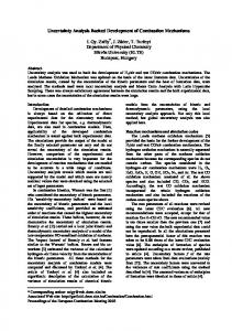
In order to reduce the elemental ions, some specific gas species participate in the reduction process which are produced through the combustion. This combustion-assisted approach allows the material synthesis procedures to be encountered with new initial conditions in order to fabricate multiple complex metallic structures. Initial tests are based on a method called paper-templating [10], which uses a paper or fiber template that is loaded with an aqueous solution of metallic ions. The template is then heated in a furnace under specific conditions, resulting in metallic structures that have the morphology of the template material. These fibrous metallic structures have high surface areas per unit of weight/volume and are permeable to gas and liquids, which makes them attractive materials for several applications including catalysis processes. In contrast to a furnace, a constant volume combustion chamber (CVCC) can potentially provide greater operational flexibility, thus enabling synthesis operations unobtainable in a furnace or oven. A CVCC, in comparison to a furnace, provides (i) higher maximum temperatures, (ii) higher pressures, and (iii) varied ambient species concentrations. Potentially, these conditions can facilitate processes that use different metals and more intricate template structures. 2. Methods / Experimental 2.1 Design / Experimental setup The 1.13 liter cylindrical combustion chamber, shown in Figure 1, has an internal height of 152.4 mm and an internal diameter of 97.18 mm. Two flanges are welded to the cylinder that then connects to the endcaps using up to 8 bolts. A test stand is assembled on interior side of the bottom end-cap using 4 spacers and bolts. The whole assembly is mounted on a frame to make the bottom flange easily accessible. The top end-cap contains a thermocouple (OMEGA KMTXL-062G-6) a pressure transducer (KISTLER 601CAA), a gas inlet/outlet, and the spark plug.
(a)
(b)
Figure 1: (a) The CVCC chamber, (b) The test stand on the bottom end-cap Using a gas delivery system, the CVCC is filled with a mixture of methane-air at a desired equivalence ratio. The spark plug is triggered by an ignition coil (40,000 V) using a custom National Instruments LabVIEW program, which also handles data acquisition. The experimental set-up is shown in Figure 2.
2
Figure 2: Experimental set up of the CVCC system 2.2 Numerical setup A three-dimensional transient simulation of the premixed methane-air charge in a CVCC is implemented using CONVERGE computational code [11]. A 21-species, 84 reaction CHEMKIN mechanism for methane combustion (GRI MECH 1.2) [12] is applied. The combustion model uses a G-equation energy source (Equation 1) as the triggering energy for spark in a premixed flame-front tracking model. In the combustion model, Gulder model and Peters model are utilized for laminar flame speed model and turbulent flame speed model, respectively. For turbulence, a Reynolds Averaged Navier-Stokes (RANS) with Re-normalization group (RNG) k-є model is applied. A variable time-step method is taken into account to observe the combustion process and heat transfer behavior properly. To capture all the events, three methods of generating cells are applied to the geometry: base grid, adaptive mesh refinement (AMR), and fixed embedding. The base grid is set to 5 mm. The AMR method is used for velocity and temperature profiles from the onset of combustion, with a same maximum embedding level of 2 for both profiles and sub-grid criterions of 1 and 5, respectively. Fixed embedding is temporarily implemented for the spark plug and its electrode through the end of the spark event, plus a permanent embedding next to the test stand with scale of 3 and 2, respectively. The use of AMR generates smaller meshes in higher gradient regions and greatly enhances computational efficiency. In this study, three initial wall conditions for the CVCC are examined: (i) no insulation, (ii) partial insulation, and (iii) adiabatic. The initial temperature and pressure of the mixture are 300 K and 1 bar. The simulation is ran for a sufficient time period in order to observe both combustion and heat transfer processes. The G-equation is derived by Peters [13] as an unsteady transport equation following the expansion of a propagating flame interface. The following equation is typically used for tracking the laminar flame position. 𝜕𝐺 (1) + 𝜌𝑢. ∇𝐺 = 𝜌𝑈! ∇G − 𝜌𝐷𝜅 ∇G 𝜕𝑡 Where 𝜌 is fluid density term, 𝑢 is the fluid velocity vector, 𝐷 is the diffusivity term, 𝑈! is the laminar flame speed, and 𝜅 is the flame stretching term. 𝜌
For turbulent flames, the equation (2) is averaged using the Favre- and Reynolds-averaged method: 3
𝜌
(2)
𝜕𝐺 + 𝜌𝑢. ∇𝐺 = (𝜌𝑈! ) ∇𝐺 − 𝜌𝐷!! 𝜅 ∇𝐺 𝜕𝑡
Where 𝜌 is the average fluid density, 𝑢 is the average fluid velocity vector, 𝜅 is the flame stretching term defined by 𝜅 = ∇. 𝑛 in which 𝑛 = −
∇! ∇!
, 𝐷!! is a diffusivity term defined by 𝐷!! =
!! !!
𝑙𝑢 !!"! !
!
in which 𝐶!
and 𝐶! are modeling constants, 𝑆𝑐! is turbulent Schmidt number, 𝑙! is the turbulent length scale, and 𝑢 ! is the turbulent velocity scale. 3. Results and Discussion 3.1 Temperature After the spark plug is triggered, the flame propagates downward through the chamber towards the test stand. The average temperature and pressure increase as the flame front progresses. The simulation results are plotted for 120 ms, from onset of ignition. Figure 3 illustrates the maximum, mean, and test stand temperatures for three cases (no insulation, insulation, and adiabatic). With regards to the test stand temperature, as the flame propagates downward and reaches the test stand, the temperature rapidly increases to the flame temperature. After the flame front passes, the temperature continues to change, dependent on the initial boundary conditions. With no insulation, the temperature slowly decreases to room temperature. As insulation is added, the temperature drops at a slower rate due to less heat transfer. The decrease, and subsequent rise in test stand temperature is due to the flame front passing the top portion, proceeding around the edges, and subsequently heating the back side of the test stand.
Figure 3: (a) mean, (b) maximum, and (c) test stand temperature for a period of 120 ms after spark triggering 3.2 Pressure The pressure history for the combustion of the methane and air mixture in the CVCC is plotted in Figure 4(a). The comparison shows that applying an adiabatic condition to the chamber wall keeps the pressure higher than in the other two cases. In the case with a constant wall temperature condition, a very rapid drop in pressure is observed due to the rapid decrease in temperature.
4
3.3 Species Figure 4(b) illustrates the time history of selected species for the no insulation and adiabatic cases. The CO and H2 species concentration are explicitly significant for property transport in material synthesis procedures since both compounds are compelling reducing agents and are commonly used for the reduction of specific compounds [10].
Figure 4: (a) maximum pressure, and (b) species history versus time: solid lines show the adiabatic condition, the dashed lines represent the no insulation case. 4. Conclusions The use of a constant volume combustion chamber (CVCC) provides a viable alternative to a furnace for some materials synthesis operations. The CVCC approach yields higher maximum temperatures and pressures, while allowing for varied ambient species concentrations, dependent on the equivalence ratio of the combustion process. An increase in insulation allows for longer durations of the high-temperature, high-pressure-conditions, as expected. Simulations indicate that the combustion process produces elevated levels of H2 and CO, two species important to several materials synthesis reactions. By allowing for a wider range of operating conditions, the CVCC can enable materials synthesis operations inaccessible to a furnace or oven. 5. Acknowledgements This authors would like to recognize the University of Massachusetts Lowell for supporting this research. 6. References [1] [2] [3]
O. Askari, Z. Wang, K. Vien, M. Sirio, and H. Metghalchi, "On the flame stability and laminar burning speeds of syngas/O 2/He premixed flame," Fuel, vol. 190, pp. 90-103, 2017. M. E. Feyz, S. I. Pishbin, M. Ghazikhani, and S. M. Razavi, "Parametric assessment of a low-swirl burner using the exergy analysis," Energy, vol. 79, pp. 117-126, 2015. E. Rokni, A. Moghaddas, O. Askari, and H. Metghalchi, "Measurement of Laminar Burning Speeds and Investigation of Flame Stability of Acetylene (C2H2)/Air Mixtures," Journal of Energy Resources Technology, vol. 137, no. 1, p. 012204, 2015.
5
[4] [5] [6] [7] [8] [9] [10] [11] [12] [13]
D. Kang, V. Kalaskar, D. Kim, J. Martz, A. Violi, and A. Boehman, "Experimental study of autoignition characteristics of Jet-A surrogates and their validation in a motored engine and a constant-volume combustion chamber," Fuel, vol. 184, pp. 565-580, 2016/11/15/ 2016. H. Kuszewski, A. Jaworski, A. Ustrzycki, K. Lejda, K. Balawender, and P. Woś, "Use of the constant volume combustion chamber to examine the properties of autoignition and derived cetane number of mixtures of diesel fuel and ethanol," Fuel, vol. 200, pp. 564-575, 2017/07/15/ 2017. M. Shahsavan and J. H. Mack, "Mixedness Measurement in Gaseous Jet Injection," engrXiv., no. engrxiv.org/w5ebh, 18 May 2017. M. Shahsavan and J. H. Mack, "The Effect of Heavy Working Fluids on Hydrogen Combustion," engrXiv., no. engrxiv.org/94s8d, 18 May 2017. M. Rahimi Boldaji, A. Sofianopoulos, S. Mamalis, and B. Lawler, "CFD Simulations of the Effect of Water Injection Characteristics on TSCI: A New, Load-Flexible, Advanced Combustion Concept," no. 58318, p. V001T03A019, 2017. D. H. Qi, B. Chen, D. Zhang, and C. F. Lee, "Optical study on the combustion characteristics and soot emissions of diesel–soybean biodiesel–butanol blends in a constant volume chamber," Journal of the Energy Institute, vol. 89, no. 4, pp. 807-820, 2016/11/01/ 2016. D. C. Christodouleas et al., "Fabrication of Paper-Templated Structures of Noble Metals," Advanced Materials Technologies, vol. 2, no. 2, pp. 1600229-n/a, 2017, Art. no. 1600229. K. Richards, P. Senecal, and E. Pomraning, "CONVERGE (Version 2.4.), Convergent Science," Inc., Madison, WI, 2017. M. Frenklach et al., "GRI-Mech---An Optimized Detailed Chemical Reaction Mechanism for Methane Combustion," November 1 1995, Art. no. GRI-95/0058. N. Peters, Turbulent combustion, Cambridge University Press, Cambridge, United Kingdom, 2000.
6