Development of a DSP/MCM Subsystem. Assessing Low-volume, Low-cost MCM Prototyping for Universities. Peyman Dehkordi, Tim Powell, Donald Bouldin.
Development of a DSP/MCM Subsystem Assessing Low-volume, Low-cost MCM Prototyping for Universities Peyman Dehkordi, Tim Powell, Donald Bouldin University of Tennessee1
Abstract This paper discusses the design and development of a general-purpose programmable DSP subsystem packaged in a multichip module. The subsystem contains a 32-bit floating-point programmable DSP processor along with 256 K-byte of SRAM, 128 K-byte of FLASH memory, 10 K-gate FPGA and a 6-channel 12-bit ADC. The complete subsystem is interconnected on a 37 mm by 37 mm MCM-D substrate and packaged in a 320-pin ceramic quad flat pack. The design has been submitted to the MIDAS brokerage service to be fabricated by Micro Module Systems. Our experience shows that low-volume MCM prototyping is achievable and somewhat affordable for universities. The design flow, electrical and thermal analyses, CAD tools, cost and lessons learned are discussed in this paper.
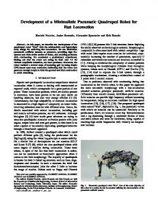
Design Flow We decided to implement a design representing a typical application of a MCM including a processor, memory and gate-array. It consists of a complete DSP subsystem based on the Motorola 96002 32-bit floating point DSP processor as shown in Figure 1. The module also includes 256 K-byte of SRAM, 128 K-byte of EEPROM, a 10 K -gate Xilinx 4010 FPGA and a 6-channel 12-bit ADC. The module was designed to exploit the multi-processing capability of the 96002. The FPGA is primarily a hardware pre-processor of incoming data but also provides other generic logic functions required for implementation of the entire subsystem.
Introduction Multichip module packaging has been in use by IBM and others for high-volume and/or high-cost products for many years but only recently has a low-volume and low-cost service become available to the design community. A variety of other reasons have also impeded growth including the availability of known good die (KGD) and the expense of sophisticated CAD tools optimized for this purpose. Previous work such as [1] discusses various MCM design techniques in depth; however, real-world MCM design problems are not well documented for the first-time users [2]. There has been a tremendous push from Advanced Research Project Agency (ARPA) for wide-spread usage of this technology for the past few years through their Application Specific Electronic Module (ASEM) program. As a result, MIDAS is now offering MCM services for lowcost prototyping [3]. As a part of our ARPA project, we have exercised the availability of this technology for universities. We have performed this exercise by acquiring the appropriate CAD tools and designing a subsystem using bare dies that were procured in small quantities within the required time period. The final design has been submitted to MIDAS for fabrication.
1
This work was sponsored in part by ARPA under grant DAAH04-94-G-0004
Figure 1. The Block Diagram of the DSP Sub-system. The design flow is shown in Figure 2 along with the CAD tools used. We had to modify our original plans several times in order to be certain that all of the dies could be acquired within the desired time frame. We found out that it is a good practice to establish a good working relationship with the die supplier to reduce the design cycle as well as die cost and to take advantage of the availability of dies which have already been tooled by the supplier. We
performed an early analysis on the candidate design to make sure the selected components would fit within the various available substrate sizes offered by MIDAS. We were constrained to select one of a few choices of substrates and packages offered by MIDAS at the time. The substrate selected is a 37 mm x 37 mm 5-layer (1 pad, 2 power, and 2 routing layers, 62 µ pitch) MCM-D based on the MMS Merged Via D500 process [4]. It utilizes copper/polymide for interconnect/dielectric and an aluminum substrate as a ground plane. The package is a cavity-down, 320-pin ceramic quad flat pack with preassigned power and ground pins and a lead pitch of 0.65 mm. Bare Die Availability
Conceptual Design
Testing Issues
MCM Availability Design Capture Mentor Design Architect
die may be $15,000. We ended up purchasing bare dies which had been only wafer probed and visually inspected. All other bare die were donated to us and had undergone similar testing which was acceptable since we will porotyping only five copies of our MCM.
Electrical Analysis Once the design was finalized and all the components were selected, the MCM physical design was performed using the Mentor Graphics MCM Station. The foundry design kit for MMS was obtained via MIDAS and facilitated template generation for the components and their bond-pads on the substrate. This included all the connections to the power and ground layers as well as thermal via generation for each die. Once a good placement of the components was reached (conforming to the electrical and thermal constraints), the critical nets were manually routed and the autorouter was then invoked. Figure 3 shows the final routed layout.
Placement Mentor MCM Station
Thermal Analysis Mentor AutoTHERM & MMS Design Kit
Routing Mentor MCM Station
Electrical Analysis QUAD XTK & MMS Design Kit
MCM Testing
Submission to MIDAS DRC, ERC, ..
Figure 2. The Design Flow and CAD Tools. Obtaining the bare dies was probably the most challenging part of this exercise. Traditionally, third party die suppliers have been providing bare dies for the MCM and hybrid markets. Due to increased MCM activities, some of the semiconductor manufacturers (i.e Intel, Motorola) have started selling some of their products in bare die form. For example, Intel offers some of its dies through its Smart die program. We have found that there is a long lead time (16 weeks) with these parts and it is necessary to execute a legal agreement between the supplier and the university. This step alone can delay a project by several months in our experience. Another issue was the minimum quantity which suppliers wanted us to buy was sometimes several hundred dies costing several thousand dollars, which exceeded our budget for this low-volume project. We contacted three die suppliers; however, only Chip Supply was very helpful with our die needs. Known Good Die was another issue we faced [5]. A true KGD (fully tested at speed and burned-in) could be very expensive, especially considering that the NRE cost for tooling a new
Figure 3. The Physical Layout of the MCM. None of the components were speed-rated due to the procurement reasons described above. We assume a nominal frequency of operation of about 40 MHz since the DSP die has come from a 40 MHz lot. The entire design was simulated with QUAD's XNS tool which uses a timedomain finite element analysis technique to compute over/under shoot, simultaneous switching noise, rise/fall times, and coupling noises on circuit networks of arbitrary topology. A typical multi-drop net model and its electrical simulation are shown in Figure 4 and 5 respectively. The maximum delay was found to exist between the DSP and the FPGA on an address line and computed to be 1.8 nS. Approximately 55% of the signals are under 1.0 nS
delay and the longest total net length including all branches was 77.286 mm. The delay distribution on the module is shown in below: percent paths exceeding 0 10 20 30 40 50 60 70 80 90 100 time(nS)|-----|-----|-----|-----|-----|-----|-----|-----|-----|-----| 0.00|************************************* 0.17 |************************************* 0.33 |************************************* 0.50 |********************** 0.67 |******************** 0.83 |************** 1.00 |********* 1.17 |***** 1.33 |*** 1.50 |** 1.67 |* The maximum crosstalk was also induced on an address line and was simulated to be 214 mV. The crosstalk was only calculated on the plane of the routed trace. The other routing plane which might couple intersecting traces was not considered. The reflections were simulated to be low since the source impedance of the driver added to the line resistance presenting a source-series termination [6]. The simulation data suggests that the limiting speed factor in this design (with the current models) would be the data bus. Almost all data lines exhibited noticeably more slewing than address lines. We were not able to get the I/O models from the die vendors. Various published I/O models from other vendors were used in the simulation. Although the results may not be very accurate (due to I/O buffer assumption), they can outline the trouble nets and general characteristics of the design. A detailed analysis is presented in [7].
Thermal Analysis MCMs integrate several large VLSI dies consuming several watts within a small area. Thermal analysis of an MCM is very important to ensure a reliable operation. The objective of thermal analysis is to predict the junction temperature of the dies in determining long-term reliability of the components and the module. The thermal path from the die to the heat sink is comprised of the following three paths [4]: Path1 = Rdie + Rdie epoxy + Rinterconnect + Rinterconnect epoxy Path2 = Rinterconnect epoxy Path3 = Rthermal grease+ Rheat sink Thermal vias were placed under all the dies to improve the thermal conductivity path from the dies to the backing plate. Thermal vias were created in such a fashion to allow two traces between them. This resulted in less routing
penalty under the dies due to the thermal vias. The junction temperature distribution is shown in Figure 5 for an ambient temperature of 25o C. The results were generated by the Mentor Graphic AutoTHERM using two-dimensional finite-element mesh analysis. The maximum junction temperature was simulated to be 50o C at the DSP which is well within the maximum rating of the dies. The module specification is shown in Table 1.
Cost & Testing Issues The purpose of this section is to provide the reader with a rather realistic cost for this MCM .We have prototyped a total of 5 MCMs which each MCM costing about $ 2,780. The total cost of the bare die was $ 1,300, assuming retail prices for the donated die. The cost of the bare dies included the dies and wafer-probe and visual inspections for the stocked dies. The substrate cost of $ 1,480 per MCM included the fabrication and test of the substrate, assembly of the dies onto the substrate and the CQFP package. The cost associated with the final system testing, design time, and the CAD tools have not been included in the $2,780. Due to their small feature sizes, MCMs cannot easily be probed or reworked [8]. Therefore, testing and fault isolation becomes a challenging area for MCM designs. Complete boundary scan testing was not feasible for this MCM since only the FPGA supported JTAG. The DSP supports a serial emulation port which was connected to the module pins along with the FPGA TAP port for testing purposes. The FPGA has a RAM-based configuration where the configuration may come from outside the module. A portion of the FPGA is configured for multi-processing bus arbitration and is connected to the internal data and address bus on the module. The FPGA can easily be reconfigured to route these lines to the module pins for possible probing and debugging during testing. The DSP has a dual data and address port architecture in which the second port was also connected to the module pins for enhanced multi-processing and testing. Testing procedures are being constructed at the time of this publication.
Conclusion Multichip modules are becoming a viable choice of packaging for high performance / miniaturized electronics. This technology is no longer considered to be an exotic technology and is being used in telecommunications, consumer electronics and workstations. Low-cost, lowvolume prototyping capabilities are a “must” for university related programs as well as small/medium size companies who wish to utilize this technology. We have found out that accessing this technology is becoming a reality for university programs at almost low-cost. The MMS designkit was very useful not only with the physical layout but also since it provided a variety of check points and design tips. Availability of the bare dies (and their I/O buffer models),
testing and rework issues will continue to be challenging issues to be considered. We are looking forward to getting the MCM back to confirm the functionality as well as validating the thermal/electrical analysis.
Substrate Package Power consumption Power Density Number of dies Number of signal nets Silicon Efficiency Average net length Longest net length Total vias Total wire-bonds Module Cost
37 mm by 37 mm MCM-D 320 pin CQFP 10 W 0.73 W/cm2 6 284 51 % 22 mm 77 mm 510 930 $ 2,780 (MCM + dies)
Table I ) Module Specification
Acknowledgments The authors gratefully acknowledge the donation of the bare-dies from Sam Valencia (Motorola), Mitch Richman (Xilinx), and Chuck Britton (Oak Ridge National Lab.). We would also like to thank Jennifer Peltier from MIDAS/ISI for her technical assistance throughout the project.
References [1] Sarfaraz, A., Swaminathan, M., Crocker, J., Bhatia, H., and M. Nealon, “Electrical Design of an MCM Package for a Multi-Processor Digital System”, IEEE Transactions on Components, Packaging, and Manufacturing Technology-PartB, Vol. 18, No. 1, February 1995. [2] Ladd, S., and J. Mandry, “Solving Real World MCM Design Problems”, Proceedings of the International Conference and Exhibition on Multichip Modules, April, 1994. [3] Peltier, J., and W. Hansford, “MIDAS: A service to Obtain Low Cost Prototype Quantities of MCM’s from Commercial Foundries”, Proceedings of the International Conference on Multichip Modules, April, 1995. [4] MicroModule Systems, Mentor Graphics, “MCM-D Technology Kit, MicroModule Systems MCM-D500 Process”, September, 1994. [5] Begay, M., Zee, J., Westbrook, G. and B. Williams, “Getting to Know Your MCM Die”, Proceedings of the International Conference and Exhibition on Multichip Modules, April, 1993.
[6] Tuckerman, D., “Electrical Design Techniques for MCM-D”, Design Tutorial of IEEE Multichip Modules Conference, March, 1994. [7] Powell, T., “The Development, Design, and Comparison of Printed Circuit Board an MultiChip Module Representations of a DSP Subsystem, Master Thesis, University of Tennessee, December 1995. [8] Flint, A. and W. Blood, “Board Test in an IC Environment”, Proceedings of the International Conference and Exhibition on Multichip Modules, April, 1993.
R
R Z = 46
Z = 46
Z = 40
Z = 40
Z = 54 Z = 54
Z = 68
Z = 65
Z = 68
Z = 54
Z = 67
Z = 67
Z = 67
Z = 53
Z = 68
Z = 54
Z = 54
V
V
Z = 40 Z = 68
Z = 40
V
Z = 40 Z = 68
V
Z = 40
V
Figure 4. A typical multi-drop net model.
Figure 5. Electrical simulation of a net.
Z = 54 Z = 54
Z = 54 R Z = 66
R D
Z = 66
Z = IMPEDANCE R = RECEIVER D = DRIVER V = VIA
Z = 68
R
Figure 6. Thermal Analysis Simulation Results.