JOURNAL OF PROPULSION AND POWER Vol. 19, No. 5, September–October 2003
Development of a Finite Element-Based Hall-Thruster Model Subrata Roy¤ and B. P. Pandey† Kettering University, Flint, Michigan 48504 This paper aims to characterize the Hall-thruster plasma dynamics in the framework of multi uid model. Effect of the ionization and the recombination has been included in the present model. Based on the experimental data, a third-order polynomial in electron temperature is used to calculate the ionization rate. The neutral dynamics is included only through the neutral continuity equation in the presence of a uniform neutral ow. The electrons are modeled as magnetized and hot, whereas ions are assumed unmagnetized and cold. The computed plasma density pro le shows that the location of the density maximum is shifted slightly inward from the channel exit. This suggests that the maximum ionization takes place inside the channel. This is in conformity with the experimental observations. The maximum electron temperature increase takes place just near the exit closer to the inner wall. This is consistent with the electron gyration velocity distribution. The plasma potential is fairly at in most parts of the channel before falling at the exit. Simulation results are interpreted in the light of experimental observations and available numerical solutions in the literature.
Nomenclature B, B E, E Ei e j; J L M m N n R r S T t u, U V, V w Z z 0 1 # º ¾ Á Ä
= = = = = = = = = = = = = = = = = = = = = = = = = = =
i k n r t z ® µ ¿ ¤,0
magnetic eld, G electric eld, V/m ionization potential electron charge, C current, mA differential operator mass matrix mass, kg basis function number density, m ¡3 solution residual radial direction Assembly operator temperature, eV time, s state variable velocity, m/s weight function ionicity axial direction ux of the propellant, m¡2 s¡1 step implicitness collision frequency ionization cross section, m2 potential, V solution domain
= = = = =
ion degree of interpolation polynomial neutrals radial component thermal velocity axial component electron or ion azimuthal component time-stepping index reference value
Superscripts
h p 0 C CC
H
= = = = =
discretization iteration index neutrals singly ionized doubly ionized
I.
Introduction
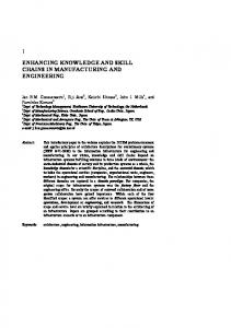
ALL-THRUSTER, also known as closed-driftthruster, experimentation started in the early 1960s, and because of a diligent Russian effort became an enabling technology for onboard propulsion in many low-Earth-orbit and geosynchronous satellites.1 The term “closed drift” refers to the azimuthal drift of electrons that is common to variantsof such thrusters,for example,stationaryplasma thruster (SPT), thruster with anode layer, etc. The SPT thruster is a coaxial device that consists of four main parts: the anode, which serves as a propellant distributor; an annular acceleration channel made of boronnitride;a magneticunit; and a hollowcathode(Fig. 1). The plasma column is contained within two coaxial dielectric cylinders that constitute the discharge channel, with the anode at one end of the channel and the exit at the other end of the channel. The discharge is created between the anode of the thruster and an external hollow cathode located downstream of the channel exit. The magnetic system consists of a series of electromagnetic coils employed inside the inner cylinder and outside the outer cylinder and predominantlyradial eld with a maximum just upstream of the channel exit. The electrons from the cathode enter the chamber and are subject to azimuthal E £ B drift. The electronsin the closed drift undergo ionizing collisions with the propellant gas. Although the magnetic eld is strong enough to capture electrons in an azimuthal drift, it is not strong enough to contain the resulting ions, which are essentially accelerated by the imposed axial electric eld. The suppression of axial electron mobility by the imposed radial eld, while leaving ion mobility unaffected, enables the plasma to support an electric eld with a potential difference close to the applied
Subscripts
c d e el H
= = = = = = = = = =
charge exchange discharge electron element Hall current
Received 29 April 2002;revision received 6 September 2002;accepted for c 2003 by Subrata Roy and B. P. Pandey. publication 9 May 2003.Copyright ° Published by the American Institute of Aeronautics and Astronautics, Inc., with permission. Copies of this paper may be made for personal or internal use, on condition that the copier pay the $10.00 per-copy fee to the Copyright Clearance Center, Inc., 222 Rosewood Drive, Danvers, MA 01923; include the code 0748-4658/03 $10.00 in correspondence with the CCC. ¤ Director, Computational Plasma Dynamics Laboratory and Associate Professor of Mechanical Engineering, 1700 West Third Avenue; sroy@ kettering.edu. Associate Fellow AIAA. † PostdoctoralResearch Associate, ComputationalPlasma Dynamics Laboratory, 1700 West Third Avenue;
[email protected]. Member AIAA. 964
965
ROY AND PANDEY
between similar particles is small in comparison with the drift between electrons and ions. The collisions between electron–neutral, electron–ion, and ion–neutral play an important role. The plasma– neutral collision usually determines the kinetics of the motion. The rate of the ion production in plasma is determined by the ionization frequency. The ionization rate is given as Sioniz D n e n n hVeth ¾i .Veth /i D k i n e n n
Fig. 1 Half-plane schematic of a single-stage stationary plasma thruster.
voltage. The ions are accelerated to kinetic energies within 80% of the applied discharge voltage.2 Present-day Hall thrusters offer speci c impulses over 1600 s, thrust over 80 mN, and power exceeding 1.5 kW at ef ciencies of about 50%. The commercial exploitation of Hall thrusters imposes a stringent constraint of trouble-free operation for more than 8000 hrs.3 The physics inside the Hall thruster has to be reasonably well understood in order to make any signi cant change in ef ciency without compromising the lifetime. This is a challenge, as the choice of thruster size requiresan optimum selectionbetween ef ciency and lifetime.4 Despite signi cant numerical and theoretical advances of the recent past, we lack an adequate numerical model to describe critical regions of a Hall-thruster plasma dynamics in a self-consistentfashion.5;6 Numerical simulation of the plasma dynamics of a Hall thruster has been carried out recently by several authors in the framework of the hybrid as well as the uid models.7¡27 The one-dimensional uid model of the partially ionized plasma incorporating the neutral dynamics and the effect of the plasma-wall interaction has been documented recently.25¡27 This present study extends the twodimensional, two- uid, fully ionized thruster plasma model of Roy and Pandey22 to a two-dimensional, three- uid, partially ionized plasma model in order to investigate the effect of ionization and recombination on the dynamics of the Hall thruster. The neutral dynamics is included in the present work because without neutral dynamics the effect of ionization and recombinationcannot be studied satisfactorily. The self-consistent two-dimensional, three- uid formulation of the bounded thruster plasma is the novel feature of the present work. To the best of our knowledge, such a simulation has not been reported in the literature. Numerical novelty includes the utilization of subgrid embedded (SGM) nite elements,28;29 for convergence and stability of the solution.It is based on a nonlinear, nonhierarchical,high-degree Lagrange nite element basis for use in a discretizedapproximation. SGM elements utilize local mesh, velocity and diffusion parameters to modify the dissipative ux-vector(second-derivative)terms in the equation. For the hyperbolic equation a second-derivativearti cial diffusion term with a vanishing coef cient is added. The theory employs element-level static condensation and eigenvalue analysis for ef ciency, nodal-rank homogeneity, and essentially nonoscillatory solution. Unlike traditional upwind methods, however, nonlinear SGM does not introduce any unnecessary diffusion to distort the solution. The numerical model and the simulation results are presented in the subsequent sections. In Sec. II we discuss pertinent theoretical issues. In Sec. III the solution algorithm is described.The numerical results are documented in Sec. IV. Finally, Sec. V contains conclusions and future work.
II.
Theoretical Issues
The dynamics of a partially ionized, thruster plasma is quite complicated,1¡3;7¡12;15;17¡20;26;27 as several elastic and inelastic processes can occur simultaneously. However, not all processes are equally probable. For example, momentum exchange between electron-electron and ion-ion will not be important in comparison with the electron–ion momentum exchange as the relative drift
(1)
where ¾i is the total cross section of the process, n e is the electron number density, and process constant ki D h¾i .Veth /Veth i, with the averaging done over the velocities of the electrons. A general electron temperature-dependent empirical formula can be tted to the ionization process constant ki D [k i0C , ki0CC , kiI CC ], corresponding to Xe0 !XeC , Xe0 !XeCC , and XeC !XeCC processes, where Xe is Xenon. We shall use the following generalized process rate that is a sum of all three ionization rates26 :
¡
¢
ki D ¡3:2087 £ 10¡5 Te3 ¡ 0:0022Te2 C 0:7101Te ¡ 1:76 £ 10¡14 (2) Electron–ion collisions on the other hand can lead to recombination. The rate of recombination is given as
«
¬
Srecom D ¡n e n i Veth ¾eir .Veth / D ¡®n e n i
(3)
where recombination coef cient ® can be approximated as30 ¡9 2
® D 1:09 £ 10¡20 n e Te
m3 /s
(4)
Slow propellant ions are created as a result of resonant chargeexchange collisions of the following types between the fast “beam” (current) ions and slow thermal neutrals: C 0 0 XeC fast C Xe slow ! Xe slow C Xe fast 0 CC 0 XeCC fast C Xe slow ! Xe slow C Xe fast 0 C C XeCC fast C Xe slow ! Xe slow C Xe fast
The collisional cross section for the preceding processes are comparable31 ¾.Xe ¡ XeC / » 4:38£ 10¡19 m2 and ¾.Xe ¡ XeCC / » 4:98 £ 10¡19 m2 . Thus, it would appear that all of the precedingprocesses are equally important. However, in the last process stripping of an electron is involved, the energy required an exceed 1 keV (Ref. 32), and, thus, the last process is ignored. The cross section for Xe-XeC for example is given by33 ¾ .Xe ¡ XeC / D [a ¡ b log10 .1u/].E i =E H /¡1:5 £ 10¡20 m2 (5) where a D 181, b D 21:2, E i D 12:13 eV, xenon ionizationpotential, and E H D 13:6 eV, hydrogen ionization potential. For a relative velocity 1u between 10 and 2 £ 103 m/s, the charge-exchange cross section varies between 10¡20 to 10¡19 m2 . Having delineated some of the important physical processes in the partially ionized thruster plasma, we shall now give the basic set of equations that describes the dynamics of the process under investigation. We shall assume that the ions are unmagnetized because for typical parameters of a thruster plasma, namely, magnetic eld B » 200 G and ion velocity 4 £ 103 m/s, the gyration radius of ions is about 0.1 m, which is much larger than the size of the thruster (0.02–0.03 m). In the present simulation the maximum value of magnetic eld, near the exit, is 242 G. Therefore, the effect of magnetic eld on the ion transport will be ignored. Further, the pressure term in the ion momentum equation can be ignored as the thermal energy of the ions is much smaller than their kinetic energy, that is, Ti ¿ m i Vi2 . Owing to the small inertia, electron-responsetime is much faster than the ion-response time. As a result, electrons will attain the steady state faster than the ions. Keeping this in mind, electron momentum and energy equations are solved at steady state, whereas for ions and neutrals a set of time-dependentcontinuityand momentum equations are simultaneously solved.
966
ROY AND PANDEY
An annular cylinder can adequatelycharacterizeHall-thrustergeometry. Ignoring any variation in the azimuthal µ direction, we shall take a two-dimensional axisymmetric r , z representation of the thruster. The following set of equations written in the component form is used to describe the dynamics of thruster plasma with the azimuthal ion velocity Viµ , and dependence on the azimuthal angle @=@µ set to zero. The continuity equation for the electron and the ions are @n ® 1 @ @.n ® V®z / C DS .rn ® V®r / C (6) r @r @t @z where S D Sioniz ¡ Srecomb . Assuming that the neutral velocity has axial component only, the neutral continuity equation is @n n @.n n Vnz / C D Srecomb ¡ ki0C n e n n ¡ ki0CC n e n n @t @z
(7)
The right-hand side of the continuity equations (6–7) represents source and sink term caused by ionization and recombination. The sink term of the neutral continuity equation (7) is slightly different than the ionizationsource term of the plasma continuityequation(6) because of the presence of the processes like XeC !XeCC in the Sioniz . The ion momentum equations are, ³ ´ Ti @n i Ze @ Vir @ Vir @ Vir C Vir C Viz D¡ C E r ¡ ºc Vir m i n i @r mi @t @r @r
³ C
´
³
me ºei .Ver ¡ Vir / ¡ 0:5ºin .Vir ¡ Vnr / C mi
Ti @n i @ Viz @ Viz @ Viz C Vir C Viz D¡ C m i ni @ z @t @r @z
³
³
S ni
´ Vir
(8)
E ´ ¡rÁ D .m e ºei =e/.Vi ¡ Ve / C .1=ene /rn i Ti
´
Ze E z ¡ ºc Viz mi
´
³
´
me S C Viz (9) ºei .Vez ¡ Viz / ¡ 0:5ºin .Viz ¡ Vnz / C mi ni The factor 0.5 before ion–neutralcollisionterm comes from reduced mass m i m n =.m i C m n / ¼ m i =2. The electron momentum equations are
¡ ºei .Ver ¡ Vir / ¡ ºen .Ver ¡ Vnr / C
(10)
C Ver
´
S Veµ ¡ .Vei C Ven /Veµ ne
(11)
e @ Vez @ Vez 1 @n e Te C Vez D¡ ¡ .E z ¡ Veµ Br / m e n e @z me @r @z
³ ¡ ºei .Vez ¡ Viz / ¡ ºen .Vez ¡ Vnz / C
´
S Vez ne
(12)
The electron energy equation is, ³ ´ © 3 @ Te C Ve ¢ r Te D ¡Te r ¢ Ve ¡ º Ver2 C Veµ2 C Vez2 2 @t
£
C 2 Ver .Veµ C Vez / C Vez Veµ C ºen .Ver Vnr C Vez Vnz / C 3 me S C3 ºen .Tn ¡ Te / C mn ne
¤ª
C ºei .Ver Vir C Vez Viz /
me ºei .Ti ¡ Te / mi
³
3 Te C ® E i 2
T¤ =m i D 2 £ 103 m/s,
where ¾¤ D ¾0
Ver Veµ e @ Veµ @ Veµ Ver C Vez C D .Vez Br ¡ Ver Bz / r me @r @z
³
p
n ¤ D 0¤ =V¤ D 0:5 £ 1017 m¡3
º¤ D ¾ ¤ n ¤ V¤ D ¾¤ 0¤ ’ 2: £ 105 s¡1
´
S Ver ne
(14)
Equation (14) yields the relationship between the current and strength of the electric eld in the plasma. The electric eld has been written in the moving frame of the plasma, that is, E ´ E0 C V £ B. Before numerically solving the preceding set of equations (6– 14), we normalize the physical variables as follows. Temperature T is normalized using the rst ionization potential of Xenon T¤ D E i D 12:1 eV. All other dependent variables can be normalized from V¤ D
V2 @ Ver @ Ver 1 @n e Te e Ver C Vez ¡ µ D .Er C Veµ Bz / r m e n e @r m e @r @z
³
where º D ºei C ºen . In Eqs. (6–13), Ve , Vi are the electron and ion velocities, respectively; n j is the number density of the j th particle with j D e and i ; ºei , ºen are the electron–ion and electron–neutral collision frequencies respectively; ºc is the ion charge-exchange collision frequency; and the value of ® is between (2–3).18 The electron dynamics are determined by the pressure gradient, electric and magnetic forces, and the collisional exchange of momentum in Eqs. (10–12). The convective term in these equations retains the effect of the electron inertia. The contributionof the electron inertia is small, and on this basis, its effect on the plasma dynamics is generally ignored. However, in the regions of sharp ow gradients the effect of the convective term can become nite, and therefore the convective term is retained in this formulation. Similarly, because collision timescales are much slower than the electron-cyclotrongyration timescale one can ignore elastic and inelastic collision terms in comparison with the Lorentz force term V £ B in the momentum equation. Such an approach will exclude the dynamics of the momentum exchange as well as the effect of ionization and recombination, severely limiting the applicability of the model to the thruster plasma. Therefore, all of the collision terms are retained in the electron momentum equations (10–12). Equation (13) includes the effect of Joule heating, a contribution caused by exchange of random thermal energy and ionization and recombination.The simulationof Katz et al.14 shows that the average ion energy remains nearly constant in the channel. Therefore, we also assume in our model that the ion energy is constant. In closure, Eqs. (6–13) are supplementedwith the simple form of Ohm’s law34
´ (13)
p
m i =m e
The fundamental length scale l0 is de ned in terms of characteristic velocity and collisional frequency l0 D V¤ =º¤ . The timescale is t0 D 1=º¤ . To solve numerically the formulation (6–14), proper initial and boundary condition speci cations are necessary to make the problem well posed. The axial velocities of electrons and ions are not xed at the inlet. Under typical conditions, next to the anode, a plasma sheath (typical width » Debye length) forms, and ions must ow into the sheath from the quasi-neutralregion.The axial velocity is near zero close to anode and then begins to rise at the edge of the acceleration zone, reaching a maximum velocity beyond the exit.21 Such ow behavior has also been observed in the classical nozzle problem, where ow changes smoothly from subsonic (in the narrow region) to supersonic ow in the divergent region. Therefore, a sonic point, where the ow velocity equals the characteristic speed of the medium, is always expected at the exit.We shall impose the choked-exit18 boundary condition for the ion axial velocity. Furthermore, axial electron ow will be assumed inward at the channel exit. We impose zero radial velocity for the electrons and ions at the inlet and leave it oating elsewhere. At the inlet the plasma density is equated to the reference value. The neutral density at the inlet depends upon the mass- ow rate. In the present calculationthe mass- ow rate is »6 mg s¡1 , a value relevant to a thruster operating at 1.5-kW power level.2;13 The correspondingneutral density is
967
ROY AND PANDEY
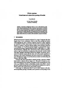
n n » 1018 m¡3 . The homogeneous Neumann condition is imposed on the electrostatic potential at the inlet. Because at the cathode the potential is zero, a vanishing potential is assumed at the outlet. For ion density a homogeneous Neumann condition is assumed. At the upstream boundary (thruster inlet plane) we specify an electron temperatureof Te D 5 eV, which is close to the experimentaldata.5;24 In a typical Hall-thruster experiment the radial magnetic eld is dominant compared to the axial eld. The radial magnetic eld decreases from a typical maximum of about 200 G near the channel exit to a much lower value (»30–40 G) near the anode,thoughhigher values of radial magnetic elds (»350 G) have been utilizedrecently for P5-class of thrusters.2 The presence of this radial magnetic eld inhibits electron ow to the anode and in the process considerably enhances the ionization caused by electron impact. In the presence of a very strong radial magnetic eld and in the absence of any collision, the axial electron current can be completely inhibited. Thus, the current is mainly carried by the ions jz ¼ ji . Assuming a quasineutral (n i ¼ n e / plasma, the Hall current per unit radius is
The spatially semidiscrete FE implementation of the weak statement W S h for Eq. (17) leads to
E B
where U.t / is the time-dependent nite element nodal vector. The time derivative dU=dt is generally replaced with a # -implicit or ¿ -step Runge–Kutta time-integration procedure. In Eq. (19), M D Sel .Mel / is the mass matrix associatedwith element-levelinterpolation, and R carries the element convection information and the diffusion matrix resulting from genuine (non-Eulerean) or numerical elemental viscosity effects and all known data. Equation (19) is usually solved using a Newton–Raphson scheme29 :
Z r³ ´
JH ¼ en e
0
dr ¼
ene Ád B
(15)
where Ád is the dischargepotential.Note that the dischargepotential is the sum of the column potential drop Á, the cathode fall potential, and the possible potential drop in the plasma region next to the exhaust and outside the cylinders. The corresponding Hall current density can be expressed as j H D ene E=B ¼ ene E z =Br For ji ¼ en e Vi we have
q
J H ¼ ji Ád =B Vi ¼ ji
m i Ád
¯
µZ W S D Sel
M
µ
(16)
Finite Element Based Modeling
Z w L.U/ dÄ D 0
1Ui D ¡ M C #1t
(17)
where w denotes any admissible test function. Thereafter, the nite element (FE) spatial semidiscretization of the domain Ä of Eqs. (6–14) employs the mesh Ä h D [el Äel and Äel is the generic computational domain where subscript el denotes a nite element. Using superscript h to denote spatial discretization, the FE weak statement implementation for Eq. (17) de nes the approximationas
el
u el .x j /;
i X
U pC1
pD0
u el .x j / D N k Uel
where the trial space FE basis set N k .x j / typically contains Chebyshev, Lagrange, or Hermite interpolation polynomials complete to degree k, plus perhaps “bubble functions.”35
³
@R @U
´¶¡1
R.U/
(20)
In Eq. (20) # is the implicitness of the numerical algorithm, and 0 < # < 1. The obvious numerical issues will be associated with calculation of the Jacobian, @R=@U, and inversion of the M C #1t .@R=@U/ matrix with suf cient accuracy. Equations (6– 14) are strongly coupled, and the Jacobian matrix for this problem becomes very stiff for a realistic mass ratio of electron and ion. This results in solution divergence for a standard Galerkin nite element approach on a moderate to ne mesh. As a remedy, we utilized a high-order-accurate SGM nite element28;29 method to achieve a stable monotone solution on a relatively coarse grid. SGM elements use statically condensed higher-degree polynomial basis functions N S for high solution delity. The choice of time step is dictated by the Courant–Friedrich– Lewy condition.37 The solution at any time step is declared convergent when the maximum residual for each of the state variables becomes smaller than a chosen convergence criterion of 2 D 10¡4 . The steady state is declaredwhen the precedingconvergencecriteria is met at the rst iteration of any time step. Here, the convergence of a solution vector U on node j is de ned as the norm: kU j ¡ U j ¡ 1 k ·2 kU j k
35
[
(19)
where 2eB 2
This work is an extension of the multivariable design code development of Roy35 and Balagangadhar and Roy.36 Using L as a differential operator, a general formulation for Eqs. (6–14) can be expressed as L.U/ D 0, where U D fn ® , Viz , Vir , Vez , Ver , Veµ , Te , ÁgT . The weak statement formed by multiplying L.U/ with an appropriate weighting function w and integrating over the computational domain (and thus weakening the continuity requirement of the nite element basis function29 / underlines the development of a range of computational- uid-dynamicsalgorithms.Such an integral statement associated with Eqs. (6–14) is
u.x j / ¼ u h .x j / D
(18)
dU C R.U/ D 0 dt
U¿i CC 11 D U¿i C 1 C 1U i D U¿ C
(15a)
where the maximum ion velocity is pVi D .2eÁ d =m i / . Clearly, for a given magnetic eld, J H =ji » Á d . For an ef cient operating system current is carried by the ions, and ions attain maximum velocity. Thus we shall anticipate that the ensuing potential distribution (and the resultant accelerating electric eld) will be in the region of maximum magnetic eld strength.
Ä
Nk L el .U/ d¿ Äel
Sel symbolizes the assembly operator carrying local (element) matrix coef cients into the global arrays. Application of Green–Gauss divergence theorem in Eq. (18) will yield natural homogenous Neumann boundary conditionsand the surface integral that contains the unknown boundary uxes wherever Dirichlet ( xed) boundary conditions are enforced. Independentof the physicaldimensionof Ä, and for generalforms of the ux vectors, the semidiscretized weak statement of Eq. (18) always yields an ordinary differential equation system:
1=2
III.
¶
h
IV.
(21)
Numerical Results and Discussion
We recall that the thruster plasma is modeled by a twodimensional axisymmetric .r -z/ geometry. The µ direction is along the azimuth. We consider a two-dimensionalmagnetic eld with radialand axialcomponents,where the radial eld is dominant(Fig. 2). The magnetic eld lines near the exit close outside the thruster indicating that the near-plume region plasma will be affected by the presence of the magnetic eld. However, the simulation domain in the present work corresponds only to the bounded region. Equation set (6–14) is solvedusing SGM nite elementson a biquadratic9 £ 9 mesh with 361 equidistant nodes. We have employed a trapezoidal
968
ROY AND PANDEY
Fig. 2 Measured radial magnetic eld in Gauss inside the thruster acceleration channel (Manzella, D., and Peterson, P., Private Communication, 2001).
time-stepping procedure, that is, # D 0:5 in Eq. (20), for this paper. In the present formulation the ion dynamics are time dependent, whereas electron dynamics have been assumed time independent. This is a plausible assumption because, owing to their small inertia, the electron will reach a steady state over the ion dynamic scale.9 The code uses variable time steps until the transient features die down and the iteration converges to a steady state. All solutions presented in this section have iterated to a steady state. Figure 3a describes the neutral density contours. We use the reference values of physical parameters pertaining to a typical 1.5-kW class thruster that has a mass- ow rate »6 mg s¡1 corresponding to n n D 1018 m¡3 . As is clear from the gure, neutral density is the highest at the inlet region and gradually decreases towards the channel exit. As ionization increases towards the exit (caused by an increase in the electron temperature), the neutral number density should decrease, and we see such a behavior. This is consistent with the fact that as a neutral enters the thruster chamber it undergoes impact ionization. Some experiment in the literature9 suggests that the minimum in neutral density is not necessarily correlated to the correspondingincrease of the ion density. However, in the present work the plasma density predictiondisplays a correlationbetween ion and neutral number densities that is similar to the reported experimental data.2;5 We attribute this correlation to the temperature-dependent, self-consistentcalculation of the ionization rate. Figure 3b plots the plasma number density contours. The ion (electron) number density increases rapidly from a base value of 1017 m¡3 and attains a maximum value 7 £ 1017 m¡3 upstream of the acceleration channel before decreasing near the exit. The experimental results2;13 show that the plasma density reaches its peak value inside the acceleration channel, near the inner wall before the exit plane. In this region the radial magnetic eld is the maximum, and thus a large number of electronsare inhibitedfrom moving in the axial direction, resulting in a high probability of impact ionization and plasma production. The maximum plasma density inside the accelerationchannel agrees with the fact that the ionization channel is well inside the thruster. There is no signi cant effect of ionization and recombination on the plasma number density. This could have been anticipated on the grounds that in a Hall thruster, where the pressure is low and ion currents exceed the electron current, the effect of the ion productionand loss to the ion continuity equation (6) is negligible.19 The experimental result for a 1.6-kW class thruster13 displays two distinct peaks in the ion number density pro le located at about 0.02 and 0.032 m from the anode. These peaks are attributed to different ionization mechanisms—to the electron thermal energy upstream (0.02 m) and to the availability of electron gyration energy at 0.032 m. These results underline the complexity of the thruster plasma dynamics and inadequacies of the existing numerical models. Several important questions need to be addressed in order to explain the physical mechanism behind the experimentally observed transition from double-hump to single-hump ion density pro le when operating at 1.6 and 3 kW.13 If at 1.6 kW plasma undergoes
Fig. 3a Neutral number density contours in meters¡3 .
Fig. 3b
Plasma number density contours in meters¡3 .
a unique ionization–recombination–ionization cycle, then such behavior should be re ected in the neutral velocity and density pro les. We anticipate that at higher operating powers of the thruster the neutral velocity will exhibit an initial increase (corresponding to the loss of slow neutrals caused by ionization, i.e., number of fast neutrals increase), then a decrease, and again an increase. Also, the neutral number density should exhibit an initial decrease, then an increase, and again a decrease in its number density. It points to the necessity of generalizing the numerical model on the one hand and further experimental investigation of the thruster plasma dynamics on the other hand. The direction of ion streamlines as plotted in Fig. 4 shows that the ion ow diverges towards the side walls in the downstream section of the channel, indicating the presence of a radial electric eld. Haas2 has experimentally inferred the presence of this radial eld, where the radial asymmetry in the ion number density has been attributed to the presence of such a eld. Figure 5 shows that the magnitude of the radial velocity contours increases in the region of strong magnetic eld Br con rming the experimental observation.2 The interaction of ions with the ambient magnetic eld could be another possible reason for divergence of the ion streamlines. The magnetic eld, which con nes the electrons in the azimuthal direction and inhibits their axial motion, can exert its in uence on ions as a result of the collisional coupling of ions with the electrons—like ambipolar diffusion in the interstellar plasma.38 Thus, even though ions are not directly coupled to the magnetic eld, they can interact with the magnetic eld through the electrons. We also anticipate that an additional divergencein the ion beam might appear once the thermal pressure gradient is included in the ion dynamics. When the ion pressure gradient is taken into account, it will give rise to a radial electric eld that can cause a dispersion of the accelerated beam. The decollimation of the ion beam in the radial direction will reduce the thrust.
969
ROY AND PANDEY
Fig. 4 Directed ion trajectories show the decollimation of ions near the channel exit. Fig. 6
Fig. 5
Radial velocity contours in meters/second.
In addition,in the presenceof ionization and recombinationthere is a slight increase in the ion radial velocity near the exit. This increase in the radial velocity could be caused by the depletion of the slow ions to the walls. However, a de nite correlation between the velocityand density can only be made if plasma-wallinteractions are also included in the model. Recent numerical studies20 suggest that plasma-wall interaction can affect the plasma density, near the exit plane. Figure 6 describes the electron temperature contours. We note that the increase in the temperature is not uniform in the channel. The maximum increase of »28 eV occurs just downstream of the center of channel towards the inner wall. The peak in the temperature can be attributed to the Ohmic heating caused by the maximum gyration energy in this region. The rise in temperature is similar to the measured electron temperature near the exit of the 1.6-kW class thruster of Haas and Gallimore.13 However, the experimental electron temperature peak is spread along a radial line concentratednear the channel exit. Our numerical electron temperature results do not clearly reproduce this pro le and can point to the limitation of the present model. Secondary electron emission, ion sputter yield, the electron near-wall conductivity,the near-wall sheath effect, etc., can all affect the electron temperature pro le. The present model will be extended to include plasma-wall interactions for better benchmarking with the experimental data. Figure7 shows the potentialcontoursinsidethe accelerationchannel. The potential is highest at the inlet (near the anode) and is set to
Fig. 7
Electron energy distribution in electon volts.
Potential distribution inside the acceleration channel in volts.
zero at the outlet (near the cathode). This is similar to the numerical approach presented by Haas.2 Although the computed potential is set to zero at the channel exit, observations2;13;16 indicate that only one-half to one-third of the potential drop actually takes place downstream of the thruster. In this numerical model the full potential drop is forced to occur inside the channel. We further note that the potential inside the channel is very sensitive to the boundary conditions on the plasma velocities. Such effects will be evaluated in more detail in subsequent versions of the model. In Fig. 8 the plasma number density,electron temperature,plasma potential along with the electric eld, and electron gyration energy are given at radial cross section r D 0:056 m, centrally located between the outer and the inner wall. We see that the plasma number density exhibits a narrow half-width at full maximum (hwfm) just upstream of z D 0:1 m, suggesting a localized ionization region. It was noted by Bishaev and Kim5 in one of the early experiments on SPT that a very small ionization region precedes the acceleration zone. Our numerical result is consistent with the experimental observations.2;5 The electron temperature Te pro le in Fig. 8 predicts a sharp increase near the inlet and then a gradual rise before reaching the maximum of about 22 eV near the two-third length downstream of the channel. This is not consistent with the trend in plasma density pro le. One would expect that the plasma density maximum will coincide with the electron temperature maximum and that the rst local maximum in electron temperature at around 14 eV at normalized axial location of 0.11 will be re ected in a
970
ROY AND PANDEY
electron dynamics is assumed time independent. By using a thirdorder electron temperature-dependent polynomial, a self-consistent calculation of the ionization rate has been carried out in the model. Our simulation results suggest that the increase in the plasma number density is correlated with the decrease in the neutral number density. The plasma density prediction is similar to the reported experimental data.2;5 There is no signi cant effect of the ionization and recombination on the plasma number density. This fact is consistent with reported observation.19 The electron temperature inside the channel shows a gradual increase at the centerline and predicts a hump upstream of the exit at a location between the centerlineand the inner wall, which is in agreement with the experimental observation2 that shows a peak next to the exit for a 1.5-kW-class thruster. The potentialpro le agrees with recent experimental studies.16 The ion streamlines suggest that ions are primarily acceleratedbecause of the axial electric eld and reach the maximum velocity near the exit plane. The ions are moving towards the side walls near the thruster exit, indicating the presenceof a nite radial electric eld. Experimental data2 con rm the presence of such a radial electric eld. The numerical results are very sensitive to boundary conditions.In the present simulation a choked-exit boundary condition has been imposed on the ion velocity. It needs to be relaxed. The ion velocity reaches the sonic velocity well inside the thruster. Therefore, boundary condition issues require a detailed investigation. The present uid model also requires further generalization to include plasma-wall interactions.The effect of inelastic processes, namely, secondary emission and sputter yield, should be incorporated.Also, proper modeling of the plasma-sheathdynamics is necessary.
Acknowledgments This work is supported by NASA Research Grant NAG3-2520 with David Jacobsonas the technicalmonitor.The authorsgratefully acknowledge the support of the Electric Propulsion group of NASA Glenn Research Center for providing magnetic eld data used in this work.
References 1 Zurin,
Fig. 8 Distribution of the density, temperature, potential,and gyration energy below the centerline (r = 0:056 m) of the acceleration channel.
small peak in the plasma density. However, the rst local maximum in the temperature might re ect the loss of slow electrons caused by recombination; because plasma number density is not a sensitive function of source or sink term,19 the local electron temperature maximum of 14 eV (at z=L D 0:11) does not affect the plasma density pro le. The computed potential pro le is consistent with the known experimental data (with uncertainty of ¡3V=C6V) for a 1.5-kW thruster that operated at 300 V.16 The potential pro le is at in most of the channel and approaches zero at the exit. Because potential is forced to zero at the exit, the simulation result starts diverging with the experimentalresult near the exit. The gyrationenergy (last frame in Fig. 8) displays an increasing trend, reaching maximum near the exit, which agrees well with the published Hall contours2;20 that display a maxima upstream of the channel exit for 1.6- and 3-kW-class thrusters. Finally, the thrust at the exit plane of the thruster acceleration channel is calculated via Eq. (24) of Haas and Gallimore.39 The simulation result shows a steady-statethrust of 79.4 mN, which is within the measured data of 95 3 mN and the calculated value of 68 mN at the exit plane of the 1.6-kW thruster.39
V.
Conclusions
In this paper a nite element based two-dimensional formulation of partially ionized plasma using multicomponent uid equation is developed in the presence of ionization and recombination. The model is then applied to study the dynamics inside the Hall thruster. The ion and neutral dynamics are time dependent,whereas
V. V., Kaufman, H. R., and Robinson, R. S., “Physics of Closed Drift Thrusters,” Plasma Sources Science and Technology, Vol. 8, No. 1, 1999, pp. R1–R20. 2 Haas, J. M., “Low-Perturbation Interrogation of the Internal and Near Field Plasma Structure of a Hall Thruster Using a High-Speed Probe Positioning System,” Ph.D. Dissertation, Dept. of Aerospace Engineering, Univ. of Michigan, Ann Arbor, 2001. 3 Choueiri, E. Y., “Plasma Oscillations in Hall Thruster,” Physics of Plasmas, Vol. 8, No. 4, 2001, p. 1411. 4 Jankovsky, R., Tverdokhlebov,S., and Manzella, D., “High Speci c Impulse Hall Thruster Technology,” AIAA Paper-99-2949, June 1999. 5 Bishaev, A. M., and Kim, V., “Local Plasma Properties in a Hall Current Accelerator with an Extended Acceleration Zone,” Soviet Physics, Technical Physics, Vol. 23, No. 9, 1978, pp. 1055–1057. 6 Kim, V., “Main Physical Features and Processes Determining the Performance of Stationary Plasma Thrusters,” Journal of Propulsion and Power, Vol. 14, No. 5, 1998, p. 736. 7 Komurasaki, K., and Arakawa, Y., “Two-Dimensional Numerical Model of Plasma Flow in a Hall Thruster,” Journal of Propulsionand Power, Vol. 11, 1995, pp. 1317–1323. 8 Fife, J. M., “Hybrid Pic Modeling and Electrostatic Probe Survey of Hall Thrusters,” Ph.D. Dissertations, Massachusetts Inst. of Technology, Cambridge, MA, 1998. 9 Boeuf, J. P., and Garigues, L., “Low Frequency Oscillations in a Stationary Plasma Thrusters,” Journal of Applied Physics, Vol. 84, No. 7, 1998, p. 3541. 10 Fruchtman, A., and Fisch, N., “Modeling of a Hall Thruster,” AIAA Paper 98-3500, July 1998. 11 Guerrini, G., and Michaut, C., “Characterization of High Frequency Oscillations in a Small Hall-Type Thruster,” Physics of Plasmas, Vol. 6, No. 1, 1999, p. 343. 12 Morozov, A. I., and Savelyev, V. V., “Fundamental of Stationary Plasma Thruster Theory,” Reviews of Plasma Physics, Vol. 21, edited by B. B. Kadomtsev and V. D. Shafranov, Consultants Bureau, New York, 2000, p. 261.
ROY AND PANDEY 13 Haas, J. M., and Gallimore, A. D., “An Investigation of Internal Ion Number Density and Electron Temperature Pro les in a Laboratory-Model Hall Thruster,” AIAA Paper 00-3422, July 2000. 14 Katz, I., Mandell, M., and Mikellides, Y., “1-D HET Code,” Maxwell Tech., Internal Memo to D. Manzella, Cleveland, 2000. 15 Litvak, A. A., and Fisch, N. J., “Resistive Instabilities in Hall Current Plasma Discharge,” Physics of Plasmas, Vol. 8, No. 2, 2001, p. 648. 16 Haas, J. M., and Gallimore, A. D., “Internal Plasma Potential Pro les in a Laboratory-Model Hall Thruster,” Physics of Plasmas, Vol. 8, No. 2, 2001, p. 652. 17 Fruchtman, A., Fisch, N. J., and Raitses, Y., “Control of the Electric Field Pro le in the Hall Thruster,” Physics of Plasmas, Vol. 8, No. 3, 2001, p. 1048. 18 Ahedo, E., Martinez, P., and Martinez-Sanchez, M., “One-Dmensional Model of the Plasma Flow in a Hall Thruster,” Physics of Plasmas, Vol. 8, No. 6, 2001, p. 3058. 19 Choueiri, E., “Fundamental Difference Between the Two Hall Thruster Variants,” Physics of Plasmas, Vol. 8, No. 11, 2001, p. 5025. 20 Keidar, M., Boyd, I. D., and Beilis, I. I., “Plasma Flow and Plasma-Wall Transition in Hall Thruster Channel,” Physics of Plasmas, Vol. 8, No. 12, 2001, p. 5315. 21 Smith, T. B., Herman, D. A., Gallimore, A. D., and Drake, R. P., “Deconvolution of Axial Velocity Distributions from Hall Thruster LIF Spectra,” International Electric Propulsion Conference, Paper IEPC-01-019, Oct. 2001. 22 Roy, S., and Pandey, B. P., “Development of a Finite Element Based Hall Thruster Model for Sputter Yield Prediction,” Proceedings of the 27th International Electric Propulsion Conference, Electric Rocket Propulsion Society, Worthington, OH, Oct. 2001. 23 Gascon, N., Meezan, N. B., and Cappelli, M. A., “Low Frequency Plasma Wave Dispersion and Propagation in Hall Thrusters,” International Electric Propulsion Conference, Paper IEPC-01-56, Oct. 2001. 24 Hargus W. A., Jr. and Cappelli, M. A., “Interior and Exterior Laser Induced Fluorescence and Plasma Measurements Within a Hall Thruster,” Journal of Propulsion and Power, Vol. 18, No. 1, 2002, p. 159. 25 Ahedo, E., Gallardo, J. M., and Martinez-Sanchez, M., “Model of the Plasma Discharge in a Hall Thruster with Heat Conduction,” Physics of Plasmas, Vol. 9, No. 9, 2002, p. 4061.
971
26 Roy, S., and Pandey, B. P., “Numerical Investigation of a Hall Thruster Plasma,” Physics of Plasmas, Vol 9, No. 9, 2002, p. 4052. 27 Roy, S., and Pandey, B. P., “Plasma-Wall Interaction Inside a Hall Thruster,” Journal of Plasma Physics, Vol. 68, No. 4, 2003, p. 305. 28 Roy, S., and Baker, A. J., “A Nonlinear, Sub-Grid Embedded Finite Element Basis for Accurate Monotone Steady CFD Solutions,” Numerical Heat Transfer—Part B, Vol. 31, No. 2, 1997, pp. 135–176. 29 Roy, S., and Baker, A. J., “A Nonlinear, Sub-Grid Embedded Finite Element Basis for Accurate Monotone Steady CFD Solutions—Part II, Navier– Stokes Solutions,” Numerical Heat Transfer—Part B, Vol. 33, No. 1, 1998, pp. 5–36. 30 Mitchner, M., and Kruger, C. H., Partially Ionized Gases, WileyInterscience, New York, 1973. 31 Gulczinski, F. S., III, “Examination of the Structure and Evolution of Ion Energy Properties of a 5 kW Class Laboratory Hall Effect Thruster at Various Operational Conditions,” Ph.D. Dissertation, Dept. of Aerospace Engineering, Univ. of Michigan, Ann Arbor, 1999, p. 142. 32 Golant, V. E., Zhilinsky, A. P., and Sakharov, I. E., Fundamentals of Plasma Physics, Wiley, New York, 1977, p. 66. 33 Pullins, S., Chiu, Y., Levandier, D., and Dressler, R., “Ion Dynamics in Hall Effect and Ion Thrusters: XeC C Xe Symmetric Charge Transfer,” AIAA Paper 2000-0603,38th Aerospace Sciences Meeting and Exhibit, AIAA, Reston, VA, 2000. 34 Spitzer, L., Physics of Fully Ionized Gases, Wiley-Interscience, New York, 1962, p. 35. 35 Roy, S., “Combining Galerkin Matrix Perturbation with Taylor Weak Statement Algorithms,” Computer Methods in Applied Mechanics and Engineering, Vol. 184, No. 1–2, 2000, pp. 87–98. 36 Balagangadhar, D., and Roy, S., “Design Sensitivity Analysis and Optimization of Steady Fluid-Thermal Systems,” Computer Methods in Applied Mechanics and Engineering, Vol. 190, No. 42, 2001, pp. 5465–5479; also “Erratum,” Vol. 191, No. 3–5, pp. 509, 510. 37 Richtmyer, R. D., and Morton, K. W., Difference Methods for InitialValue Problems, 2nd ed., Wiley-Interscience, New York, 1967. 38 Spitzer, L., Physical Processes in the Interstellar Medium, Wiley, New York, 1978. 39 Haas, J. M., and Gallimore, A. D., “An Investigation of Internal Ion Number Density and Electron Temperature Pro les in a Laboratory-Model Hall Thruster,” AIAA Paper 2001-3507, July 2001.