Advance Publication by J-STAGE Mechanical Engineering Journal
DOI:10.1299/mej.15-00570
Received date : 14 October, 2015 Accepted date : 3 July, 2016 J-STAGE Advance Publication date : 11 July, 2016
© The Japan Society of Mechanical Engineers
Development of a local light stimulation device integrated with micro electrode array Hidetaka UENO*, Shoji KOMAI**, Kyohei TERAO***, Hidekuni TAKAO***, Fusao SHIMOKAWA***, Hidetoshi KOTERA**** and Takaaki SUZUKI* *
Division of Mechanical Science and Technology, Gunma University 1-5-1, Tenjin-cho, Kiryu, Gunma 376-8515, Japan E-mail:
[email protected] ** Division of Biomedical Science, Nara Institute of Science and Technology 8916-5, Takayama-cho, Ikoma, Nara 630-0192, Japan *** Department of Intelligent Mechanical System Engineering, Kagawa University 2217-20, Hayashi-cho, Takamatsu, Kagawa 761-0396, Japan **** Department of Microengineering, Kyoto University Yoshida-honmachi, Sakyo-ku, Kyoto 606-8501, Japan
Abstract In this paper, we propose a simple plasma-less fabrication and integration method for biomicrodevice applications. For optogenetics, microlenses and pinholes irradiating local sight of biological tissue with focused visible light and electrodes measuring a biological electropotential are integrated by using organic materials such as polymer. The proposed fabrication method consists of photolithography and wet-etching process only. The shape of fabricated microlenses measured by a white light interferometer was the diameter of 111.5 m, the depth of 45.5 m, and the focal length 320 m. The impedance of Platinum black electroplated on the fabricated electrode pads was reduced to 200 k. As the results, it is succeeded to integrate electrode pads, microlenses and pinholes without plasma etching process. The fabricated dish is assembled with a light irradiation device having two LEDs. By the light irradiation test, the fabricated dish is expected to be utilized in a variety of neuroscience researches. By the test for cytotoxicity, it is succeeded to create neural network on the fabricated dish. Key words : Microlenses, Polymer, Bio MEMS, Integrated device, Neural network
1. Introduction Recently, a lot of researches for a micro device using organic material such as polymer were carrying out (McDonald, 2000; Amato, 2012; Chuang, 2003; Shiraishi, 2014; Yoo, 2015). Organic materials have low Young modulus, high ductility, high chemical resistance and biocompatibility in comparison to inorganic material. In the research field of MEMS (Micro Electromechanical Systems), many kinds of polymer-MEMS devices, such as large-deflection polymer MEMS mirror (Miyajima, 2001; Fujita, 2005) and micro actuator (Ezkerra, 2011), and optical guide plate (Lee, 2007) were proposed by using photoresist as a drive structural material. One of features of the organic material is to deposit as liquid on a substrate and biocompatibility. Since polymer is easy deposited in comparison to inorganic materials deposited by sputtering and vaporization, micro-lens for optical communication is easy fabricated by using polymer. Example of fabrication methods for micro-lens are the reflow process (Lian, 2014) and the gray mask process (Yang, 2007). On the other hand, polymer is used for bio device because of biocompatibility (Esch, 2012). Bio MEMS devices which aims to elucidate biological systems and improve a medical technique have to fulfill not only the suitable design value for a biological tissue and biocompatibility but also the disposability for preventing contamination and sanitation. However, fabrication process of a biomicrodevice tends to become complicated and laborious because of integration with a measuring and a stimulating functions on one dish. Especially, Si plasma etching
© The Japan Society of Mechanical Engineers
such as Bosch process is used for fabricating the complicated three dimensional structures. However, there are concerns about biocompatibility and complex fabrication process. Recent years, a lot of researches about bio MEMS devices made of polymer have carried out because of biocompatibility and easy to fabricate for three dimensional shape (Tamai, 2015). However, integration of organic and inorganic materials is difficult because of different characteristics between each material. So, it is necessary to develop a simple integration method for complicated bio MEMS devices. A bio MEMS device for Optogenetics is as an example of the integrated bio MEMS devices. The purpose of elucidating neural network, one of the most undiscovered organ in human body, is to create treatment method for neural disease such as Alzheimer. The fMRI is used as the method for elucidating about brain (Savoy, 2012). The function of brain parts, formal lobe, temporal lobe and occipital lobe, are elucidated. However, using the fMRI method, it is difficult to elucidate the role of neuron and neural network system. Neural network formed by neurons in the brain communicates by sending sodium ion and chloride ion as electro signal. Electric stimulation is commonly used in the conventional research for neuron and neural network, however it is difficult to elucidate each neuron’s role because of the propagation of electric stimulation. Recently, optogenetics is the novel technique for elucidating neural network. In this method, opsin protein is created in the neuron’s ion channel by gene expression (Deisseroth, 2011). Opsin is one kind of protein and contained in algae such as the Chlamydomonas, Volvox and Natronomonas pharaonic in the natural world. Each opsin has different affection to neuron. For example, channel rhodopsin 2 makes sodium ion pass through when blue light is irradiated. Halorhodopsin makes chloride ion pass through and stop the neuron’s activity when orange light is irradiated. It is possible to control neurons activity by Optogenetics. In conventional methods for Optogenetics, tiny LED or optical fiber is used as light source, and a probe integrated with micro electrodes for measuring neuron’s electro reaction (Kobayashi, 2014; Lu, 2012; Kwon 2013). Fabrication method for tiny electrodes and electrode pads is also developed (Green, 2010; Yand, 2005; Gao, 2013). A probe-formed MEMS device is also integrated with LED or light guide for stimulating inside of the brain (Tagawa, 2010; Wu, 2013). However, this kind of devices stimulates multitude neurons because of light disperse. Thus, it is difficult to elucidate each neuron’s role in neural network by stimulating each neuron. So, it is necessary to make locally concentrated light power of over 1mW/mm2 for irradiating to individual neuron. In this study, we propose a fabrication method for three dimensional microstructures combined polymer and inorganic materials. This proposed method is expected that it is useful for research about biology such as Optogenetics field because it is needed to conduct light stimulation and measuring neuron’s electric reactions. To stimulate local area in biological tissue and acquire reactions from it, three components which are microelectrodes, microlens and pinholes are integrated on one dish. Usability of the proposed dish is evaluated by measuring electrodes impedance, focal length of microlens and brightness of each lights which is pass through pinhole and microlens. Furthermore, we culture neuron from mouse fetus on same environment as the proposed dish to evaluate its cytotoxicity. Our final goal is to fabricate micro device which is capable of using in animal brain for long term. Therefore, we culture neuron and observe the state of that neuron created neural network to certify that the proposed dish had no cytotoxicity and be used in biological tissue for long term. Furthermore, it is evaluated that proposed method is useful for Optogenetics and expected that allow of local stimulation in neural network.
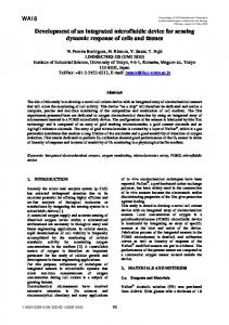
2. Principal of integration method for bio MEMS devices 2.1 Simple integration method for three dimensional microstructures Integration method of three dimensional microstructures made of organic and inorganic materials without plasma etching is proposed. By depositing polymer on three dimensional microstructures fabricated by wet etching, three dimensional polymer structure is fabricated without complicated exposure method. In general, rigid exposure value and contact alignment are necessary to form 3D structures by lithography. On the other hand, 3D microstructures are automatically and simply formed due to directly deposit photoresist on the device double as a photomask. 2.2 Principal of light stimulation and measuring neuron’s electro reaction Figure 1 shows the principal of light stimulation and neuron’s electric reaction measurement on a dish. Electrode pads are fabricated on a glass substrate. Microlenses for creating focused light is distributed in the array of electrode pads. Neurons which create the neural network is place on these electrodes and microlenses. Visible lights having different wave length are focused by each microlenses and irradiated to the local sight in the neural network. Electric reactions of each neuron in the neural network are measured by each electrode pad. The neural network activity is visualized by measuring the neural network’s electric reactions.
© The Japan Society of Mechanical Engineers
Figure 1 Principal of light stimulation and electrical reaction measurement. Focused visible lights by each microlenses are irradiated to neurons on the dish surface. This action makes two kinds of neurons excited and inactive in the neural network. Reaction of neural network is measured by electrodes.
3. Fabrication of local light stimulation dish 3.1 Dish configuration Figure 2 shows the proposed dish integrated with electrode pads and microlenses. A pyrex glass is adopted as a main substrate having high thermal resistance. There are 64 electrode pads fabricated on the center of the pyrex glass substrate within 1 mm square. Since the size of neuron is from 20 to 30 m and the interval of neurons about 50 m, the size of electrode pads is designed to 50 m square and interval of 150 m. Platinum black is electroplated on electrode pads to decrease electric impedance. Four hollows as microlenses are fabricated on the back side of the pyrex glass substrate. Thick negative photoresist SU-8 is deposited on electric wirings to protect wirings and restrict the measuring area. SU-8 is also deposited on the back side of the substrate for fabricating microlenses by using difference of refractive index between pyrex glass and SU-8. Pinholes are fabricated on the microlenses by sputtering and patterning Cr layer.
Figure 2 Schematic of the proposed dish. (a) The dish has 64 electrode pads in the center of the dish. Each pad side is 50 m square and the interval of which is 150 m. (b) The dish is composed by 6 layers. The layers except platinum black layer are fabricated by simple photolithography and wet etching. Platinum black is electroplated on Au electrodes for decreasing the electrode’s impedance.
© The Japan Society of Mechanical Engineers
3.2 Fabrication process Figure 3 shows fabrication process of the proposed dish. Firstly, Au layer is deposited on each sides of a pyrex glass (Matsunami glass ind.,ltd.). The thickness of Au layer for electrode pads and electrodes is 1000nm. The thickness of Au layer for protective layer of the hollows as microlenses is 400nm. Each Au layer is deposited by RF magnetron sputtering (Canon Anelva Corp.). Four hollow patterns having the diameter of 10 m are fabricated on the back side of Au layer by photolithography using positive photoresist s1805 (Rohm and Hass Electronic Materials Corp.) and etching process using iodine-potassium iodide solution composed of iodine and potassium iodide and ultrapure water with ratio of 3:20:250. Then, hemisphere shape for microlenses at the hollow patterns are formed by isotropic wet etching by using hydrofluoric acid. For fabricating electrode pads and electrodes, Au layer is formed by photolithography using s1805 and wet etching using the iodine-potassium iodide solution. Au layer on the back side is etched at same time. For restricting measuring area, SU-8 3005 (Microchem Corp.) is coated on the electrodes except for electrode pad’s surface. After SU-8 3005 is cross linked, SU-8 3050 is deposited as the thickness of 100 m on the back side of the substrate by spray coater (Nanotec Corp.). SU-8 3050 is patterned for microlenses by feeding into the hollows fabricated by hydrofluoric acid (Oh, 2010). On SU-8 3050 layer, Cr layer is deposited by sputtering and wet-etched for 4 pinholes to restrict light passing through the microlenses. Finally, platinum black layer is electroplated on electrode pads by using the electroplating apparatus (Yamamoto-MS corp.).
Figure3 Fabrication process of the proposed dish. First, hollows are fabricated by HF wet etching (a). Second, electrodes are fabricated on dish by wet etching using iodine-potassium iodide solution (b). SU-8 3005 is deposited as a polymer layer for protecting on upper-side of the substrate (c), and SU-8 3050 as a polymer layer for forming microlens (d). For each microlens, pinholes are fabricated by patterning Cr layer (e). Finally, platinum black is electroplated (f). 3.3 Fabrication results Figure 4 shows photographs of the fabricated dish and the center of the dish. 64 electrode pads and electrodes are fabricated. Irradiated light is transmitted through the dish. Diameter and depth of the fabricated microlens was measured by a white light interferometer (Bruker AXS Corp.). The diameter of microlens d is about 111.5 m, and the depth hL about 45.5 m. The curvature radius R is calculated by equation (1).
R K 1
hL d / 2 , 2 2hL 2
(1)
where Conic constant K is 0. So, radius R is about 56.9 m. Then, the focal length f is calculated by Equation (2).
© The Japan Society of Mechanical Engineers
f
R , n2 n1
(2)
where refraction index of glass n1 is 1.47, and refraction index of SU-8 n2 1.65. The calculated result is about 316 m. Moreover, for evaluating the surface of the microlens, SEM images of the transferred profile of the microlens were taken. The mold was fabricated by PDMS molding. It is confirmed that there are no cracks and warps on lens’s surface by the SEM image (Furjes, 2014; Byun 2014).
Figure 4 Photographs of the fabricated dish (a). In the center of fabricated dish, there are 64 electrode pads (b). Transmitted light from back side the dish is observed on the dish surface (c).
Figure 5 Surface profile of the fabricated microlenses. (a) The image capture of the lenses is taken by the white light interferometer. The diameter of the lens is 111.5 m, depth 45.5 m, and the focal length 320 m. (b) To evaluate the lens surface profile, the lens is transferred by PDMS molding. It is confirmed that there are no cracks and warps on lens’s surface observed by a SEM image. Figure 6 shows photographs of the fabricated electrode pads observed by a digital optical microscope and a scanning electron microscope. It is confirmed that platinum black is electroplated for each electrodes on the dish. The impedance of electrode pads measured in KCl solution are shown in Table 1. The impedance was reduced by electro plating.
© The Japan Society of Mechanical Engineers
Figure 6
Photographs of electrode pads covered by platinum black. All electrode pads are electroplated. Table 1
Electric properties of electrode pads.
Electrodes
Impedance (average) [kΩ]
Standard deviation [kΩ]
Impedance (maximum) [kΩ]
Impedance (minimum) [kΩ]
Au Platinum black
1176.0 221.5
48.0 92.5
1350.0 460.0
1090.0 28.0
4. Assembly with light irradiation device Figure 7 shows schematics of the proposed light irradiation device. The device is composed of a print circuit board, aluminum jigs and two LEDs having the power of 3 W. The LED changes the irradiating wavelength within visible light. The jigs are made of aluminum for heat dissipation from the LEDs. Each jig has alignment structures. Inside the assembled jig is separated into two rooms for installing the LEDs. The fabricated dish is fixed on the top of the light irradiation device for observing neurons by an optical microscope. Figure 8 shows photographs of the fabricated device. Two LEDs are installed in the Al jig. Table 2 shows photographs of visible light irradiated from the LED through the pinhole and the microlens, and the brightness measured by the image analysis. Since the RGB color light is stimulated, the proposed device is expected to locally stimulate neural network with visible light.
Figure 7 Schematics of light stimulating device. (a) Configuration of the dish and the light source device. The device size is 100 mm square. (b) The device is composed of the fabricated dish, printed wiring board and Al jig having two LEDs to irradiate multi-wavelength of visible lights.
© The Japan Society of Mechanical Engineers
Figure8 Photographs of the fabricated device. (a) the fabricated dish combined with the light source device. (b) the light source device made of Al jig integrated with LEDs. Table 2 Color
Brightness and locality of light irradiation with each wavelength. Red Green Blue White
Picture
Brightness
173
156
177
255
5. Cell culture on fabricated device The cytotoxicity of the proposed dish is depended on surface materials which is touched cells or medium. Thus, it is necessary to evaluate the effects from surface materials to neurons. Almost the proposed dish surface was covered by SU-8. Cytotoxicity about surface materials was evaluated for each kind of cells (Hennemeyer, 2008). In this research, cytotoxicity for neurons was evaluated by cell culture. The purpose of this research is to measure the electrical reaction from neurons. Thus, it is necessary that neurons maintain their function on the fabricated dish. Neurons which was cone cell from mouse fetus were placed on materials used for the proposed dish, and cultured over one week. In general, normal neurons connect each other by making axis cylinders and create neural network. So, the cytotoxicity of surface materials was evaluated by observing the growth of axis cylinders between each neuron. An inverted microscope is suitable to observe neurons. However, the proposed dish has Cr layer on the back side of the substrate and it is difficult to observe neurons by using the inverted microscope. So, we fabricated a cytotoxicity test dish having same condition without Cr layer. Figure. 9 shows the fabrication process of the test dish for evaluating cytotoxicity of the proposed dish. First, Au electrodes were patterned. Second, SU-8 layer was formed by photolithography. Then, glass ring was adhered for fabricating chamber for cell culture. Finally, Platinum black was electroplated on each electrode pads. Figure 10 shows the fabricated dish which is visible to use the inverted microscope. For finding optimum condition for neurons, three items were compared. First, the hard bake temperature for SU-8 was modified from 120 °C to 200 °C. Second, adhesive agent was modified epoxy resin (Duralco 7050-2, TAIYO WIRE CLOTH) or PDMS. Third, coating material was modified Poly-D-lysine or Nutragen collagen. Poly-D-lysine is one of the basic amino acid and support to connection between substrate and neurons by ion binding. Nutragen collagen is made of skins from cattle. Figure 11 shows the neurons cultured over one week on the fabricated test dish. On a general polystyrene dish, there were a lot of neurons and axis cylinders. (Fig. 11a) On the test dish having 120 °C hard bake and using epoxy resin (Duralco 7050-2, TAIYO WIRE CLOTH) for adhesive agent and using only Poly-D-lysine, there were no axis cylinders and neural network was not created. (Fig. 11b) When using 200 °C hard baked SU-8 and Poly-D-lysine and Nutragen collagen, it was succeeded to create neural network on the test dish. (Fig 11c) This result was seemed to be caused by changing temperature of hard baking for SU-8. Since the proposed dish is fabricated by same fabrication process, it is possible to create neural network on the proposed device.
© The Japan Society of Mechanical Engineers
Figure.9 Fabrication process of a cytotoxicity test dish with no pinhole layer. (a) Fabricating electrodes on glass substrate by photolithography and etching process. (b) Patterning SU-8 layer by photolithography. (c) Adhering glass ring for fabricating chamber for cell culture. (d) Electroplating platinum black layer on every electro pads.
Figure.10
Photograph of the fabricated test dish having no pinhole layer and microlens on the backside.
Figure.11 Photographs taken by the inverted microscope of neurons in three types of dishes. (a) Cultured cell on a general polystyrene dish. (b) Cultured cell on the test dish having SU-8 surface baked 120 °C, using only poly-Dlysine for coating. (c) Cultured cell on the test dish having SU-8 surface baked 200 °C, using poly-D-lysine and nutragen collagen (Type I) for coating.
6. Conclusions We proposed a simple integration method for polymer MEMS device to fabricate three dimensional microstructures without complicated exposure method and contact alignment. Electrode pads, microlenses and pinholes were integrated in center of the fabricated dish within the area of 1 mm square for optogenetics. After combining the fabricated dish and the light source device, light irradiation through microlenses were evaluated by a fluorescent microscope and the brightness were suitable for stimulating neurons. Neurons from mice cultured on same surface of the fabricated cytotoxicity test dish were created neural network, it was shown that proposed dish had high bioavailability for neurons. From these results, the proposed method is expected to be utilized for fabricating bio device especially which is for neuro science such as optogenetics researches.
© The Japan Society of Mechanical Engineers
Acknowledgements This work was partly supported by JSPS KAKENHI Grant Number 26289067, Kagawa University Characteristic Prior Research fund 2013-2015, Nanotechnology Platform by MEXT and Research Fellow of the Japan Society for the Promotion of Science (16J12039).
References Amato, L., Keller, S., Heiskanen, A., Dimaki, M., Emneus, J., Boisen, A., and Tenje, M., “Fabrication of high-aspect ratio SU-8 micropillar arrays”, Microelectronic Engineering, Vol.98, pp. 483-487, 2012. Byun, I., Coleman, A., and Kim. B., “SAM meets MEMS: reliable fabrication of stable Au-patterns embedded in PDMS using dry peel-off process”, Microsystem Technologies, Vol.20, pp.1783-1789, 2014. Chuang, Y., Tseng, F., Cheng, J., and Lin, W., “A novel fabrication method of embedded micro-channels by using SU-8 thick-film photoresists”, Sensors and Actuators A, Vol.103, pp. 64-69. 2003. Deisseroth, K., “Optogenetics”, Nature Methods, Vol.8, No.1, pp.26–29, 2011. Esch, M., Sung, J., Yang, J., Yu, C., Yu, J., March, J., and Shuler, M., “On dish porous polymer membranes for integration of gastrointestinal tract epithelium with microfluidic ‘body-on-a-dish’ devices”, Biomedical Microdevices, Vol.14, pp.895–906, 2012. Ezkerra, A., Fernandez, L., Mayora, K., and Ruano-Lopez, J., “A microvalve for lab-on-a-dish applications based on electrochemically actuated SU8 cantilevers”, Sensors and Actuators B, Vol.155, pp.505-511, 2011. Fujita, T., Maenaka, K., and Takayama, Y., “Dual-axis MEMS mirror for large deflection-angle using SU-8 soft torsion beam”, Sensors and Actuators A, Vol.121, pp.16–21, 2005. Furjes, P., Holczer, E., Toth, E., Ivan, K., Fekete, Z., Bernier, D., Dortu, F., and Giannone, D., “PDMS microfluidics developed for polymer based photonic biosensors”, Microsystem Technologies, Vol.21, pp.581-590, 2014. Gao, K., Li, G., Liao, L., Cheng, J., Zhao, J., and Xu, Y., “Fabrication of flexible microelectrode arrays integrated with microfluidic channels for stable neural interfaces”, Sensors and Actuators A, Vol.197. pp. 9-14, 2013. Green, R., Ordonez, J., Schuettler, M., Poole-Warren, L., Lovell, N., and Suaning, G., “Cytotoxicity of implantable microelectrode arrays produced by laser micromachining”, Biomaterials, Vol.31, pp.886–893, 2010. Hennemeyer. M, Walther. F, Kerstan. S, Schürzinger. K, Gigler. A, and Stark. R, “Cell proliferation assays on plasma activated SU-8”, Microelectr. Eng. Vol. 85, pp. 1298-1301, 2008. Kobayashi, T., Masuda, H., Kitsumoto, C., Haruta, M., Motoyama, M., Ohta, Y., Noda, T., Sasagawa, K., Tokuda, T., Shiosaka, S., and Ohta, J., “Functional brain fluorescence plurimetry in rat by implantable concatenated CMOS imaging system”, Biosensors and Bioelectronics, Vol. 53, pp. 31–36, 2014. Kwon, K., and Li, W., “Integrated Multi-Led Array with Three-Dimensional Polymer Waveguide for Optogenetics”, Journal of Microelectromechanical Systems, Vol.10, pp.1017-1020, 2013. Lee, J., Lee, H., Lee, B., Choi, W., Choi, H., and Yoon, J., “Simple liquid crystal display backlight unit comprising only a single-sheet micropatterned polydimethylsiloxane (PDMS) light-guide plate”, Optics Letters, Vol. 32, No. 18, pp.2665-2667, 2007. Lian, Z., Hung, S., Shen, M., and Yang, H., “Rapid fabrication of semiellipsoid microlens using thermal reflow”, Microelectronic Engineering, Vol.115, pp. 46-50, 2014. Lu, Y., Li, Y., Pan, J., Wei, P., Liu, N., Wu, B., Cheng, J., Lu, C., and Wang, L., “Poly(3,4ethylenedioxythiophene)/poly(styrenesulfonate)-poly(vinyl alcohol)/ poly(acrylic acid) interpenetrating polymer networks for improving optrode-neural tissue interface in optogenetics”, Biomaterials, Vol.33, pp.378-394, 2012. McDonald, C., Duffy, D., Anderson, J., Chiu, D., Wu, H., Schueller, O., and Whitesides, G., “Fabrication of microfluidic systems in poly (dimethylsiloxane)”, Electrophoresis, Vol.21, pp.27-40, 2000. Miyajima, H., Asaoka, N., Arima, M., Minamoto, Y., Murakami, K., Tokuda, K., and Matsumoto, K., “A Durable, ShockResistant Electromagnetic Optical Scanner With Polyimide-Based Hinges”, Journal of Microelectromechanical Systems, Vol.10, No.3, pp.418-424, 2001. Oh, H., Kim, G., Seo, H., Song, Y., Lee, K., and Yang, S., “Fabrication of micro-lens array using quartz wet etching and polymer”, Sensors and Actuators A, Vol.164, pp.161–167, 2010. Savoy, R., “Evolution and current challenges in the teaching of functional MRI and functional brain imaging”, NeuroImage, Vol.62, pp.1201–1207, 2012. Shiraishi, N., Kimura, M., and Ando, Y., “Basic characteristics of polycarbonate-based dual cantilever sensors for
© The Japan Society of Mechanical Engineers
detecting VOC”, Mechanical Engineering Journal, Vol.1, No.5, MN0055, 2014. Tagawa, A., Minami, H., Mitani, M., Noda, T., Sasagawa, K., Tokuda, T., Tamura, H., Hatanaka, Y., Ishikawa, Y., Shiosaka, S., and Ohta, J., “Multimodal Complementary Metal–Oxide–Semiconductor Sensor Device for Imaging of Fluorescence and Electrical Potential in Deep Brain of Mouse”, Japanese Journal of Applied Physics, Vol.49, 01AG02, 2010. Tamai, H., Maruo, K., Ueno, H., Terao, K., Kotera, H., and Suzuki, T., “Development of low-fluorescence thick photoresist for high-aspect-ratio microstructure in bio-application”, Biomicrofluidics, Vol.9, 022405, 2015. Wu, F., Stark, E., Im, M., Cho, I., Yoon, E., Buzsaki, G., Wise, K., and Yoon, E., “An implantable neural probe with monolithically integrated dielectric waveguide and recording electrodes for optogenetics applications”, Journal of Neural Engineering, Vol.10, 056012, 2013. Yang, J., Kim, D., Hendricks, J., Leach, M., Northey, R., and Martin, D., “Ordered surfactant-templated poly (3,4ethylenedioxythiophene) (PEDOT) conducting polymer on microfabricated neural probes”, Acta Biomaterialia, Vol.1, pp.125–136, 2005. Yang, J., Liao, Y., and Chen, C., “Fabrication of long hexagonal micro-lens array by applying gray-scale lithography in micro-replication process”, Optics Communications, Vol.270, pp.433-440, 2007. Yoo. S., and Toi, Y., “Numerical simulation of mechanical sensors using hydrated IPMCs”, Mechanical Engineering Journal, Vol.2, No.1, 14-00326, 2015.
© The Japan Society of Mechanical Engineers