Available online at www.sciencedirect.com
Procedia Engineering 41 (2012) 1469 – 1475
International Symposium on Robotics and Intelligent Sensors 2012 (IRIS 2012)
Development of a Low Cost Small Sized In-Pipe Robot Md Raziq Asyraf Md Zin, Khairul Salleh Mohamed Sahari*, Juniza Md Saad, Adzly Anuar, Abd Talip Zulkarnain Centre for Advanced Mechatronics and Robotics, Universiti Tenaga Nasional, Jalan IKRAM-UNITEN, 43000, Kajang, Selangor, Malaysia.
Abstract This thesis reports the process of design and development of a low cost small sized in-pipe inspection robot. Problem of a pipe inspection operation surfaces when the robot only has a limited coverage of the inner surfaces of the pipe. Moreover, current solutions are largely sized and are not appropriate for smaller sized pipelines. Feasibility study completed produced a set of design requirements to be met for the final design to be able to operate inside a pipeline with inner diameter ranging from 80 mm to 180 mm. The use of magnets was decided as an adhesion system to allow the robot a full range of motion inside the pipe. Technical analyses were completed in parallel with the design work to ensure the design remains up-to-date in case there are changes in the off-the-shelf components used. A prototype of the final design was fabricated. Tests completed successfully demonstrated the robot traversing vertically and upside down on ferromagnetic surfaces, further proving the feasibility of the motor selection analysis. Moreover, the final design prototype managed to successfully satisfy the main objective of the project by being able to fit in a pipe environment with inner diameter ranging from 80 mm to 180 mm.
© 2012 The Authors. Published by Elsevier Ltd. Selection and/or peer-review under responsibility of the Centre of Humanoid Robots and Bio-Sensor (HuRoBs), Faculty of Mechanical Engineering, Universiti Teknologi MARA. Open access under CC BY-NC-ND license.
Keywords: mechanical design, pipe inspection robot, mobile robot, magnetic wheel
1. Introduction Pipelines have been a major component for many industries that keep the world running. Water supply, oil and gas, power plants, and even beverage manufacturers, among others, are some of the industries that rely on working pipelines. However, due to agents such as aging and physical damage from other sources, defects can occur in these piping systems. Inspection of pipeline is an important task so as to ensure there are no defects that may eventually lead to problems such as leakage, which in the worst case scenario may lead to a fatal hazard such as an explosion. The main concern in designing a mobile platform or robot for traversing through pipelines is how to tackle varying pipe geometry such as pipe branch, changing diameters, and pipe elbows [1]. There are a number of robot designs that feature advantages and disadvantages when utilized to traverse through these types of pipe geometry. Pipe branch however presents a larger obstacle for the design when compared to pipe elbows and changing diameters. Varying diameters in a pipeline are still a linear path and will only pose a problem to some robot designs where their working principle is based on the internal diameter of the pipe such as the wall press robot. Similarly, pipe elbows are also a linear path for the robot to traverse through and will only need little extra consideration for the design. Pipe branches, on the other hand, does not present a linear path and may be geometrically complex [1].
* Corresponding author. Tel.: +603-8921-2020 E-mail address:
[email protected]
1877-7058 © 2012 Published by Elsevier Ltd. Open access under CC BY-NC-ND license. doi:10.1016/j.proeng.2012.07.337
1470
Md Raziq Asyraf Md Zin et al. / Procedia Engineering 41 (2012) 1469 – 1475
There are several journals and articles [4-9] documenting different designs for an in-pipe inspection robots such as the Magnebots [2], Kantaro [3], and MRINSPECT II [1]. These robot designs differ in varying aspects such as the locomotion which includes the wall-press designs and the simpler four wheel configuration reminiscent of a remote controlled car. These designs feature their own advantages and disadvantages when utilized for the different types of pipe geometry. This paper presents the processes undertaken during the design and development of a small size in-pipe inspection robot for the purpose of boiler header inspection. The robot will be used for pipeline internal inspection tasks where human insertion is not possible or difficult. Inspection will be done visually through a camera probe which will be loaded onto the robot, which acts as a mobile platform. The design will also incorporate an adhesive system to allow vertical motion within the pipe ensuring maximum inspection coverage. The main obstacle in designing an inspection robot for a small size environment such as a boiler header lies within the geometry of the boiler header itself. The boiler header consists of two main dimensions any design will have to adhere to, the internal diameter of the entry point (nipple) and the internal diameter of the boiler header itself. For this particular design, the diameter of the boiler header ranges from 80 mm (nipple) to 180 mm. While it is possible to design a platform small enough to fit the entry point of 80 mm diameter, the problem occurs in providing maximum inspection coverage of the main part of the boiler header where the size is considerably larger and movement of the fiber optic camera is limited. Thus, to negate this issue an adhesive system is incorporated into the design to allow full 360° motion within the boiler header, ensuring all internal surfaces can be reached by the fiber optic camera. 2. Robot Design The final design work has been based mostly on the robot’s capability to fit inside the entry point of 80 mm diameter and to be able to sustain the robot weight and extra payload at any position in the pipeline. 2.1. Required Wheel Torque Considering the small size requirements of the design, it is imperative for the driver of the robot to be as small as possible. A smaller motor would allow for a more forgiving tolerance for other parts of the robot without interfering with the dimensional constraints. In lieu with the attempt to create a simple design to drive cost down, RC Servo motor type was selected citing its small size potential and high torque capability as its advantages.
Fig. 1 Free body diagram of acting forces on the wheel
Referring to Fig. 1, in order to calculate the required torque, three sources of forces were taken into account namely the gravitational forces, rolling frictional forces, and sliding frictional forces. The equation derived towards calculating the required wheel torque by taking into account the gravitational, sliding frictional and rolling frictional forces is given by (1) Referring to Eq. 1, for gravitational force, both the mass of the whole robot structure and the fibre optic camera cable were taken into account. While initially the preliminary calculations were completed using estimated values, the final calculation however was completed using final values where the mass of the robot is 0.398 kg with the mass of the fibre optic camera cable set at 1.0 kg. For the rolling frictional force, the pulling strength of the magnet was also taken into
Md Raziq Asyraf Md Zin et al. / Procedia Engineering 41 (2012) 1469 – 1475
1471
account due to its effect on the wheel’s rolling capability. Using a factor of safety of two, an assumption value of 3kg magnet pulling strength was used. The magnet strength and the total weight of both the robot and cable were then summed up to calculate the rolling frictional force to be overcome. For the sliding frictional force, assuming no slippage occurs between the wheel and the pipe surface, the only source of sliding frictional force is provided by the dragging of fibre optic camera cable along the surface of the pipe. As such, only the mass of the cable was taken into account in calculating the sliding frictional force. The required motor torque can then be calculated using the maximum value of required force to move the robot multiplied with the radius of the wheels. Assuming a wheel diameter of 32 mm, the maximum torque required to drive the robot is 6.26 kg-cm when the robot is inclined at an angle of 90 degrees. Using this value, the Hitec HS-225MG mini servo (see Fig. 2) was selected for the final design as the robot driver. Capable of producing up to 4.8 kg-cm of torque each, the HS-225MG servo is also reasonably small sized, making it optimal for the final design citing the dimensional constraints, while the cost is also cheap.
Fig. 2 Hitec HS-225MG Servos
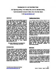
The HS-225MG servo is also modifiable to allow for continuous rotation, a key requirement for the selection of the RC servo. Two of this servo is used for the final design, totalling up to 9.6 kg-cm of torque which is sufficient to overcome the maximum required torque. 2.2. Magnetic Wheel The magnet disc used for the inspection robot wheel rim is the Neodymium (NdFeB) magnet type, a type of rare-earth magnet widely used for modern equipment such as hard disk drives and motors. This type of magnet presents the only viable solution for the magnet wheel application due to its high strength to size ratio. The wheel rim (see Fig. 3) was designed to house the magnet discs and was fabricated using a ferromagnetic alloy; Low Carbon 1018. The timing pulley was also designed into the wheel rim as a method of reducing the robot’s overall width. Three screw holes were placed along the wheel perimeter to serve as a locking mechanism for the magnet discs. A rectangular slot was designed on the wheel rim to accommodate the removal of the magnet discs using small tools, taking into account the strength of the magnets and the difficulty to remove them without using any tools. The effects of the magnet discs on the wheel rim were analysed using FEMM 4.2 software (see Fig. 4). This analysis was done to see how much pulling strength was provided by the magnet discs using the wheel rim as a magnet conductor.
(a)
(b)
Fig. 3 (a) Designed empty wheel rim and (b) completed prototype of wheel rim with magnet disc slotted in
1472
Md Raziq Asyraf Md Zin et al. / Procedia Engineering 41 (2012) 1469 – 1475
Fig. 4 Magnetic field plots and effects when the wheel rim is at different angles
From the plots produced, it was observed that the maximum pulling strength provided by the magnet discs are at a vertical position (same values facing up and down) with a total value of 49.1 N (5.00 kg). The pulling force reaches a minimum value when the magnet discs are at a horizontal position, totalling 32.8 N (3.34 kg). The mass of the robot including fibre optic camera cable totals 1.398 kg (13.71 N). Taking safety factor of 2 into account, the required magnetic force is 27.42 N. Therefore, since the minimum pulling force is higher than the required magnetic force, it was concluded that the wheel rim and magnet disc design is able to sustain the total weight of the robot. 2.3. Power Transmission with Timing Belts Timing belt was selected as method of power transmission between the front and rear wheels. As an alternative to using combinations of shaft and bevel gears, the timing belt proved to be the simpler choice for this particular robot design due to fewer components needed, resulting in better space economy. The use of timing belt also allowed for space clearance between the front and rear wheels which are required to overcome 90 degrees pipe intersections (see Fig. 8(b)). With the robot driver set as the HS-225MG servo (see Fig. 2), the power transmitted and tension forces induced on the tensioner shaft can be calculated using the following equations: P = v (F1 – F2) = v F1 (1- e-PT ) Fi = F1 + F2
(2) (3)
where P is the power transmitted, μ is the coefficient of friction, Fi is the initial belt tension, F1 and F2 are the tension values at the two ends of the timing belt lapping the wheel rim pulley, and θ is the timing belt lap angle around the wheel rim pulley. Since the initial tension of the belt can be adjusted using a tensioner designed to be adjustable, a range of initial tension ranging from 0 to 1 N was used to calculate the forces F1, F2, and power transmitted. Assuming the initial tension is set at 4 N, the power transmitted using the timing belt will be 0.47 W. 2.4. Robot Steering Mechanism Utilizing differential drive system, the method of controlling the robot depends on the synchronization between the servo controlling the left side wheels and the servo controlling the right side wheels of the robot. As the left and right wheel rotates at different speeds to turn the robot, the fixed-orientation wheels are then dragged or skids across the ground as the robot turns. This type of steering is called skid steering. 2.5. Major Robot Dimensions The design of the robot has been scrutinized at every level to ensure that all the design requirements (see Table 1) laid out during the quality function development process of the project are met, especially to ensure the final design is able to fit through the entry diameter of 80 mm.
Md Raziq Asyraf Md Zin et al. / Procedia Engineering 41 (2012) 1469 – 1475
1473
Table 1. Final Design Characteristics
No.
Engineering Characteristics
Threshold Target (Maximum or Minimum)
Final Value
1
Width of robot
80mm
73.00mm
2
Height of robot
80mm
51.65mm
3
Length of robot
170mm
79.70mm
4
Wheelbase distance
70mm
40.8mm
5
Weight
3.5kg
1.398kg
6
Magnetic wheel Force
32.8N – 49.1N
7
Max capable wheel torque
0.941Nm (9.6 kg-cm)
8
Operating voltage
5V – 6V
The threshold target values represent the absolute maximum for the major dimensions of the robot to be able to operate within the target working environment. Successfully achieving these values meant that the final design is operable within the target working environment (see Fig. 5(a)).
(b)
(a)
Fig. 5 Final design (a) in an entry point with 80 mm internal diameter and (b) completed prototype
3. Experimental Results and Discussion 3.1. Prototype Testing Prior to the testing process, a set of objectives to be achieved by the test describing the design functionality was laid out. The prototype testing objectives are: 1. 2. 3. 4.
To ensure the robot is capable of moving forward and backward in a straight line. To ensure the robot is capable of steering, and turning on its axis (on axis rotations). To ensure the robot is capable of traversing through sharp intersections (90° intersections). To ensure the robot is capable of achieving Objectives (1)-(3) on an inclined (90° and 180° inclinations) ferromagnetic metallic surface (for servo motor and magnetic wheel testing).
For the first test, in order to move the robot in a straight line, the left and right wheels will have to be rotating in the same direction with matching speed. Depending on the direction of rotation of both left and right wheels, the robot can then be made to move forward or backward. The prototype was then moved onto the steel plate to test its linear movements when inclined at an angle of 90° and 180° (upside down) (see Fig. 6). This test also served as a proof of concept for the motor selection analysis where it was calculated that the load is highest when the robot is vertically inclined due to the effects of the magnetic force and the servos having to sustain the robot weight which reaches its maximum effect when the angle of inclination is 90°.
1474
Md Raziq Asyraf Md Zin et al. / Procedia Engineering 41 (2012) 1469 – 1475
(a)
(b) Fig. 6 Linear steering on (a) 90° inclined steel surface and (b) 180° inclined steel surface
The second test aims to test the ability of the robot to be steered in different directions using its differential drive system. Largely known as skid steering or differential steering, there are two methods of steering the robot. The main method of steering the robot is called on-axis rotation. To turn the robot on its axis (on the spot), the rotation direction of the left wheel will have to be the opposite of the rotation direction of the right wheel (see Fig. 7).
Fig. 7 On-axis rotations on a vertically inclined steel surface
The clearance space between the front and rear wheels, and the use of timing belts with tensioner shaft for power transmission were designed specifically to allow the robot to be able to clear the sharp edge at the boiler header entry point exit (see Fig. 8).
Fig. 8 Sharp intersection in a boiler header
Fig. 9 Prototype robot clearing 90° intersections
Md Raziq Asyraf Md Zin et al. / Procedia Engineering 41 (2012) 1469 – 1475
1475
The prototype was tested to ensure that it is capable of traversing sharp intersections. Referring to Fig. 9, it was observed that the clearance space between the front and rear wheels was sufficiently designed as it was able to clear the sharp edge of a 90° intersection. 3.2. Limitations During the testing of the completed design prototype, it was observed that the magnetic force provided by the NdFeB magnet discs was sufficient to sustain the robot’s total weight. However, as more weight was applied to the robot (to simulate the weight of the fiber optic camera cable), wheel slippage also starts to occur. The slippage is most evident during linear motion up a vertically inclined steel surface. The cause of the wheel slippage can be contributed to the very low coefficient of friction between two metallic surfaces. A solution to reduce or eliminate wheel slippage is by using rubber padding to cover the outside surface of the wheels. This will contribute towards a higher coefficient of friction between the steel pipe surface and the robot wheels. The use of Low Carbon 1018 Steel for the fabrication of the wheel rim also posed a problem as it is prone to oxidation or rust. While not very damaging at the early stage, rusting could be problematic considering the working environment of pipe inspection robots. The material for the wheel rim should be replaced with rust-resistant alloy such as galvanized high carbon steel which features a thin coating of electro-statically bonded zinc to prevent oxidation. 4. Conclusions This paper proposed a highly mobile robot for pipeline exploration utilizing magnetic wheels as means of vertical travel that can be used for the inspection of pipelines with internal diameter ranging from 80mm upwards. The use of magnetic wheels allows the robot to be operated in any pipeline sizes provided its minimum allows entry for the robot. The final design also has the advantage of being highly mobile while also mechanically simple, consisting of two servos directly connected to the wheels with timing belts for power transmission. Furthermore, having RC servos also helped to reduce the cost of the robot. Limitations of the robot remain at the material selection level and its inability for use with non-ferromagnetic alloy pipelines. The integration of a control system onto the robot chassis along with wireless control for long range operation remains as a future work. Acknowledgements The authors would like to thank TNB Research for the funding and also technical support. References [1] Roh, S.G., Choi, H.R., 2005. Differential drive in-pipe robot for moving inside urban gas pipelines. IEEE Transactions on Robotics 21(1), pp. 1-17. [2] Alexander, H. S., Shorya, A., John, H., 2002. “Magnebots – A Magnetic Wheels Based Overhead Transportation Concept,” Proc. of the 2nd IFAC Conference on Mechatronics Systems, Berkeley, USA, December. [3] Amir, A. F. N., Yoshinori, K., Alireza, A., Yoshikazu, M., Kazuo, I., 2007. “Concept and Design of a Fully Autonomous Sewer Pipe Inspection Mobile Robot Kantaro,” Robotics and Automation, 2007 IEEE International Conference, April, pp. 136-143. [4] Bretl, T., Rock, S., Latombe, J., Kennedy, B., Aghazarian, H., 2004. “Free climbing with a multi-use robot,” Proc. International Symposium on Experimental Robotics, pp. 449-458. [5] Choi, H.R., Ryew, S.M., 2002. Robotic system with active steering capability for internal inspection of urban gas pipelines. Mechatronics 26(1), pp. 105-112. [6] Horodinca, M., Doroftei, I., Mignon, E., Preumont, A., 2002. “A simple architecture for in-pipe inspection robots,” International Colloquium on Mobile and Autonomous Systems, Magdeburg, Germany, June. [7] Ryew, S.M., Baik, S.H., Ryu, S.W., Jung, K.M., Roh, S.G., Choi, H.R., 2000. “In-pipe inspection robot system with active steering mechanism,” Intelligent Robots and Systems (IROS 2000), Proc. IEEE/RSJ International Conference 2000, November, pp. 1652-1657. [8] Tache, F., Fischer, W., Moser, R., Mondada, F., Siegwart, R., 2007. “Adapted magnetic wheel unit for compact robots inspecting complex shaped pipe structures,” Proc. of the 2007 IEEE/ASME International Conference on Advanced Intelligent Mechatronics (AIM’2007) Zurich, Switzerland, pp. 1-6. [9] Tǎtar, O., Mândru, D., Ardelean, I., 2007. Development of mobile minirobots for in-pipe inspection tasks. Mechanika Journal 6(68), pp. 60-64.