Advances in Aircraft and Spacecraft Science, Vol. 2, No. 1 (2015) 17-44 17
DOI: http://dx.doi.org/10.12989/aas.2015.2.1.017
Development of a multidisciplinary design optimization framework for an efficient supersonic air vehicle Darcy L. Allison1, Craig C. Morris1a, Joseph A. Schetz1b, Rakesh K. Kapania1c, Layne T. Watson2d and Joshua D. Deaton3e 1
Department of Aerospace and Ocean Engineering, Virginia Tech, Blacksburg, VA, 24061, USA Department of Computer Science and Mathematics, Virginia Tech, Blacksburg, VA, 24061, USA 3 Department of Mechanical and Materials Engineering, Wright State University, Dayton, OH, 45435, USA 2
(Received July 2, 2014, Revised September 4, 2014, Accepted September 5, 2014)
A modular multidisciplinary analysis and optimization framework has been built with the goal of performing conceptual design of an advanced efficient supersonic air vehicle. This paper addresses the specific challenge of designing this type of aircraft for a long range, supersonic cruise mission with a payload release. The framework includes all the disciplines expected for multidisciplinary supersonic aircraft design, although it also includes disciplines specifically required by an advanced aircraft that is tailless and has embedded engines. Several disciplines have been developed at multifidelity levels. The framework can be readily adapted to the conceptual design of other supersonic aircraft. Favorable results obtained from running the analysis framework for a B-58 supersonic bomber test case are presented as a validation of the methods employed. Abstract.
aircraft design; multidisciplinary design optimization; supersonic air vehicle; conceptual design; embedded engine and airframe integration Keywords:
1. Introduction 1.1 Background A multidisciplinary design optimization (MDO) framework has been developed for design studies of the so-called efficient supersonic air vehicle (ESAV). An ESAV is an advanced concept vehicle that is required to operate in the subsonic, transonic, and supersonic regimes. However, the majority of its flight would be at a cruise Mach number in the range of 2.2 to 2.5. It has a long mission radius, must be capable of carrying a payload, and must be designed for survivability. A
Corresponding author, Ph.D. Student, E-mail:
[email protected] a Ph.D. Student, E-mail:
[email protected] b Professor, E-mail:
[email protected] c Professor, E-mail:
[email protected] d Professor, E-mail:
[email protected] e Ph.D. Student, E-mail:
[email protected] Copyright © 2015 Techno-Press, Ltd. http://www.techno-press.org/?journal=aas&subpage=7
ISSN: 2287-528X (Print), 2287-5271 (Online)
18
Darcy L. Allison et al.
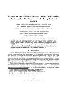
Fig. 1 A notional efficient supersonic air vehicle concept
Fig. 2 An efficient supersonic air vehicle notional mission profile
notional ESAV configuration is shown in Fig. 1 and a typical mission profile is shown in Fig. 2. This aircraft is to be designed under the constraints that it must be tailless and have embedded engines. The highly coupled aero-structural-propulsive phenomena associated with an ESAV create a formidable set of design challenges not seen in more conventional supersonic aircraft design and create a higher level of design complexity. That is, open literature aircraft MDO frameworks cannot treat this particular design problem with its specific operational requirements (Giunta 1997, Ozoroski et. al. 2010, Choi et. al. 2009). The framework remains under active development and includes components for propulsion, geometry, aerodynamics, engine exhaustwashed structures, structures, weights, mission performance (including take-off and landing), stability and control, radar cross section, noise, and optimization. Currently, a low fidelity structures model is used; however, a higher fidelity FEM model is under development. This higher fidelity structures model and the stability and control model are currently being prepared for framework integration. The ESAV framework is to be used for exploring the design space and performing ESAV MDO. This work details the development of the novel aspects of this supersonic aircraft MDO framework. The resulting framework has the capacity to model the pertinent physics required by the specific ESAV application, and find an optimum aircraft design to perform the constrained long-range mission.
Development of a multidisciplinary design optimization framework...
19
1.2 ESAV mission A representative ESAV mission is shown in Fig. 2. This simplified mission profile begins with take-off and climb while accelerating to the supersonic cruise Mach number. The runway length is not specified but is taken as a maximum of 10,000 ft. (3048 m). The supersonic cruise phase is next followed by a 2.5g, 180° turn. The return trip to the originating airfield consists of a supersonic cruise, descent, 20 minute hold/loiter, and landing. The amount of reserve fuel is assumed to be 5%. In addition, a standard atmosphere is assumed for the entire mission profile. 1.3 Design goal The measure of what makes one design better than another is a pivotal choice in the design process. Let 𝑋 0 ⊂ ℝ𝑛 and let 𝑓: 𝑋 0 → ℝ, 𝑔: 𝑋 0 → ℝ𝑚 , and : 𝑋 0 → ℝ𝑘 . The optimization problem can be stated as (Mangasarian 1969) 𝑚𝑖𝑛 𝑓(𝑥⃗),
𝑥⃗∈𝑋 0
𝑠𝑢𝑏𝑗𝑒𝑐𝑡 𝑡𝑜: 𝑖 (𝑥⃗) = 0, 𝑖 = 1, … , 𝑘,
(1)
𝑔𝑗 (𝑥⃗) ≤ 0, 𝑗 = 1, … , 𝑚. f(x⃗⃗) is called the objective function, dependent on the vector 𝑥⃗ of design variables. The problem can be constrained by both equality, 𝑖 (𝑥⃗) = 0, and inequality constraints 𝑔𝑗 (𝑥⃗) ≤ 0. The set 𝑋 = *𝑥⃗ ∈ 𝑋 0 | (𝑥⃗) = 0, 𝑔(𝑥⃗) ≤ 0+ is called the feasible set. The traditional design goal, or objective function, for aircraft is to minimize the take-off gross weight (TOGW). Jensen et al. (1981) selected seven different, but valid, figures of merit to optimize, and made comparisons. These figures of merit are TOGW, life cycle cost (LCC), acquisition cost, flyaway cost, LCC/productivity, direct operating cost, and fuel weight. An accumulative penalty was calculated for each figure of merit by summing penalties imposed by the other six figures of merit on the design with a given minimum (optimal) figure of merit. It was assumed that each of the seven figures of merit had the same weighting and were therefore equally important. The results showed that minimizing the TOGW had a relatively low accumulative penalty. That is, minimizing the TOGW caused only minor detrimental effects to the other important considerations. Choosing the minimization of the TOGW as the optimization objective function is more than just a traditional design goal; it does well to balance the other important considerations represented by the other figures of merit. The TOGW not only indicates the aircraft cost to the first order (Nicolai and Carichner 2010), but also indicates the efficiency of the whole resulting aircraft system in performing the proposed mission. Therefore, the definition of the best ESAV design herein will be the feasible design that has the minimum TOGW. It is noted that the MDO framework itself is designed to be flexible and is, therefore, capable of easily working with a different objective function (including a multiobjective function).
2. Multidisciplinary design optimization framework Typical MDO frameworks for an aircraft include analyses for aerodynamics, structures,
20
Darcy L. Allison et al.
performance, and propulsion among others. These have been previously demonstrated in other works (Ozoroski et al. 2010, McCullers 2011, Rallabhandi and Mavris 2008, Choi et al. 2008). The current framework has been built with some similar tools as these previous works, but has added a suite of critical capability central to the ESAV concept. Propulsion analyses have been done before, and even Numerical Propulsion System Simulation (NPSS) models in MDO frameworks (Lee et al. 2011). However, the NPSS models have been implemented into the MDO framework via a surrogate model that will introduce additional error that would not be present with a direct NPSS analysis. Therefore, this work takes one step further and incorporates a stable direct NPSS simulation capability that can be tractably used in the ESAV MDO framework. Other nonconventional MDO analyses have not been included together in known previous MDO frameworks in the literature. These are an engine exhaust-washed structures (EEWS) analysis, a radar cross section (RCS) analysis, and a planned stability and control analysis that assesses dynamic stability and flying qualities for conceptual design (Morris et al. 2012). The EEWS analysis was desired due to an expensive lesson learned from the B-2 bomber where the hot engine exhaust adversely affected the aircraft's aft-deck, causing premature structural cracking and expensive and frequent rework (Haney 2006). It is desired in this work to include these physical effects in the ESAV conceptual design stage. The RCS analysis was added due to the criticality of survivability to the success of the proposed mission. The stability and control analysis in this conceptual design effort was identified for the unique problems associated with the tailless design of the assumed configuration. Optimization is necessary to find the best design, not just a good enough design that works. However, optimization specifically requires an automated framework to be constructed within which the design process can be completed. The ESAV MDO framework defines and organizes all analyses required to characterize the ESAV response in its mission envelope and puts the optimizer in control of the chosen design parameters or variables so it can find the optimal design point. For this optimization problem, the objective function is computed from the output of the analyses, given a design point. The (globally) optimal design (𝑥̅ ) is 𝑥̅ ∈ 𝑋 = *𝑥⃗ |𝑥⃗ ∈ 𝑋 0 , (𝑥⃗) = 0, 𝑔(𝑥⃗) ≤ 0+
(2)
𝑓(𝑥̅ ) = min 𝑓(𝑥⃗).
(3)
such that 𝑥⃗∈𝑋
It must be remembered, however, that the optimal design only has meaning as related to the choices made by the design engineer in setting the design space boundaries, expressed in the set 𝑋 0 and the functions 𝑓, 𝑔, and . Although this expression is for the global optimum, there are no current optimization methods that can guarantee an identified optimal design as being the global optimum for the ESAV, or any other nonconvex optimization problem. The choices of the design engineer are critical to the eventual optimal ESAV design. Some of these choices are what base/starting configuration of the vehicle/system is to be optimized (often referred to as a design sketch), the choice of analysis methods to be used and their fidelity level, the selection of design parameters and their bounds, and the choice of the objective function of the design. Several more could be listed. Each of these are examples of important design functions that are prerequisite to performing any aircraft MDO. It is easy to see that choosing a different alternative for any of these by the designer will typically lead to a different optimal design. Therefore, the engineer or group of engineers in control of the multidisciplinary design
Development of a multidisciplinary design optimization framework...
21
Fig. 3 A representative ESAV N2 diagram indicating the structure of the ESAV MDO framework
optimization process wield a significant influence on the eventual final design. A convenient tool to represent a MDO framework is the N2 diagram (Lano 1977). A representative ESAV N2 diagram is shown in Fig. 3. The shaded boxes on the diagonal indicate the analysis models and the implementation of the optimization method. The MDO framework is set up so that each analysis indicated in the diagonal boxes, starting on the top left, is performed
22
Darcy L. Allison et al.
sequentially towards the lower right. This does not preclude each individual analysis from being performed using parallel computing methods, but output from upstream analyses is the input for downstream analyses, so the upstream analyses must be done first. The off-diagonal boxes on the upper triangle indicate data passed forward to ensuing analyses, while the lower triangle boxes indicate data passed back to previous analyses for either the next sequential analysis run, or for an iteration between discipline analyses. If there is a pass-back data relationship that requires iteration, the sequence is halted at that point, and the analysis is returned to the earlier discipline model until the iteration has converged. A successful pass completely through the diagonal constitutes a complete analysis run of one aircraft configuration, the output being the objective function value for a single vector of design variables. An example of an internal iteration within an individual is the one performed between propulsion and geometry (see Fig. 3) explained in Section 3. The optimizer is in control of the global design variables, and these are changed according to its specific algorithm after a complete diagonal pass for the next sequential analysis run. The ESAV MDO framework has been developed under the philosophy of preserving modularity. That is, a specific discipline model can be replaced by another model of the same discipline without having to change other framework disciplines' input/output interfaces to the new model. This feature of the framework allows for multifidelity modeling capability. It also allows different models at the same fidelity level to be used interchangeably. The modularity goal is important because, in practice, the input/output of the analysis computer programs are rarely compatible, requiring considerable effort for translator/wrapper programs represented in the offdiagonal (data transfer) boxes of the N2 diagram. In some instances, the physics of one fidelity level model may be inadequate to supply required information to another disciplinary model. In this case a helper or linking code will be required to produce the missing output or provide a value through some other method, like empirical data fits or surrogate models. The optimizer's changed design variables could be either perturbations on the last design point 𝑥⃗, as in many gradient-based optimization schemes, a point randomly chosen by a stochastic method, as in many genetic algorithms, or a point deterministically chosen as most promising, as in direct search algorithms. Thus, the framework must be able to analyze any configuration whether it is related to the previous one or not. There are both global and local design variables that are part of this MDO framework. The global design variables are represented by the vector 𝑥⃗ . The analyses that are underlined (propulsion, structures, and stability and control) in Fig. 3 signify a local optimization on local design variables or an iterative loop on local design variables. These local variables cannot change the global design variables and are thus constrained. For example, the structures model will be free to choose the optimal structural design as long as it fits within the outer mold line (OML) that is defined by a subset of the global design variables, 𝑥⃗. The geometric OML design variables are central to the MDO of the ESAV (and any airplane MDO in general), and thus show the significance of the geometry model as part of the analysis. In addition to the geometric global design variables that define the OML and mission parameters like cruise altitude and Mach number (see Table 3), the engine parameters of thrust, pressure ratios, bypass ratio, and internal variable geometry parameters are also global design variables. The OML variables for the ESAV are listed in Table 1, and further details are in another work (Morris et al. 2014). The choice of which variables to use as design variables is a good example of how the choices of the engineer influence the final optimum aircraft. Although global ESAV design variables are listed herein, this in no way limits the framework's ability to add many more different variables available in the disciplinary analyses. The construction of the framework allows great
Development of a multidisciplinary design optimization framework...
23
ease in choosing other possible variables when desired. The classification of the chosen framework used for the ESAV MDO follows the work of Martins and Lambe (2013) where all known MDO architectures are divided and subdivided into specific headings. Based on the descriptions of these architectures, this work uses the monolithic multidisciplinary feasible architecture. From Fig. 3 it can be seen that the problem is highly coupled, and therefore the monolithic architecture is chosen to simplify the problem solution. The specific advantage of the monolithic multidisciplinary feasible approach is that the optimizer is only in direct control of the design variables and constraints making the optimization problem as small as it can be for a monolithic architecture. Also, if the optimization process ends early for whatever reason, the best design up to that point is feasible (unless no feasible design had been found at the time of the cessation of optimization) and can be used either as is, or as a starting point for a new optimization.
3. Propulsion The propulsion analysis is critical to the design of an ESAV. By looking at the technical specifications of past supersonic aircraft, like the B-58, the B-70, and the Concorde, a general trend emerges that about half of their TOGW is fuel weight. This highlights the importance of having a propulsion model that is able to accurately predict engine operation (and thereby fuel burn). In addition to fuel weight, the dry engine weight is not a negligible part of the TOGW of the aircraft. Its effects are from the weight of the actual engine, its placement on the aircraft (e.g., wing engines tend to decrease the weight of the wing), and its secondary effects like structural weight, drag, and inertial properties that affect the control system design. The engine dimensions are an important factor in determining the aircraft size. This includes the inlet, cowls, and engine itself. The fuel burn, measured with the specific fuel consumption (SFC) throughout the specified mission, is the most important factor in determining the interior volume required for fuel tanks. The ESAV MDO framework has two available propulsion models. The first is the propulsion module that is part of NASA’s Flight Optimization System (FLOPS) software (McCullers 2011). To use the FLOPS propulsion model in the framework, the user first makes a selection from a list of predefined engine cycles (or a custom cycle can be defined). Various other parameters can also be chosen, such as whether to include boattail drag or not, the power extraction value, or if there is an afterburner or not. The program then generates an engine input deck on the order of a second that is used by other FLOPS modules in the MDO framework – weights, mission, and noise. Due to the criticality of the propulsion analysis for a supersonic aircraft, the principal propulsion analysis in the ESAV MDO framework uses the state-of-the-art NPSS software. NPSS was developed by a collaborative partnership between NASA Glenn, the U.S. aeropropulsion industry, and the U.S. Department of Defence (NPSS 2010). NPSS is a component-based objectoriented engine cycle simulator. An engine model is built up in an NPSS input file, component by component, using related built-in objects (called elements) in its own programming language (very similar to C++). These components are appropriately linked together in the same input file. Other input files instruct the code on the NPSS solver details of the defined engine cycle and off-design cases, specify the format the results will be written in and which results will actually be written, provide data maps of engine components, and give instructions on how to put all of these files together to run the NPSS analysis for the engine of interest. The ESAV MDO framework has three different parameterized engine cycle models available
24
Darcy L. Allison et al.
Fig. 4 Four-shock inlet configuration with ramp angle design parameters
for use in optimization studies. The first is a simple single spool turbojet engine, the second is a low bypass two spool engine, and the third is a simple variable cycle engine. The variable cycle engine model is the default in the ESAV MDO framework because of its increased efficiency over the three flight regimes encountered in an ESAV mission over the other two fixed-geometry cycles. The engine weight is calculated using the program Weight Analysis of Turbine Engines (WATE). Specifically, an object-oriented version, with improvements over the original FORTRAN code (Tong and Naylor 2009, Tong et al. 2004), was chosen. This code, called WATE++, has been directly integrated into NPSS by NASA. Therefore, all of the required thermodynamic data from the NPSS solution is immediately and easily available to WATE++ for engine and component weight estimation. The combined NPSS/WATE++ propulsion model is considered a medium- to high-fidelity model. It runs on the order of a minute on a desktop PC, which is relatively quick for this level of fidelity. This run time is acceptable for the ESAV conceptual design level studies employing the model. The ESAV inlet is designed based on a four-shock external compression ramp design. This design has three oblique shocks followed by the terminating normal shock as shown in Fig. 4. A four-shock design (rather than a three- or two-shock design) was chosen for efficiency based on the high cruise Mach number and the long duration flight at this Mach number. An additional oblique shock could have been added for a five-shock design, but an additional ramp would increase complexity and weight. Also, the expected increase in total pressure recovery going from three to four oblique shocks is relatively small (Seddon and Goldsmith 1999). The resulting twodimensional flow problem's simplicity aided in reducing the computational expense required of a more complex three-dimensional flow problem inlet, which is desired for conceptual design. The inlet design parameters are the three ramp angles, 𝜃1 − 𝜃3 . A local optimization is performed in order to choose the three angles that maximize the value of the total pressure ratio from the freestream to the flow behind the normal shock at the cruise Mach number and maximum cruise altitude. The height of the cowl and length of the ramp are determined based on the idealized constraint that all shocks meet at the cowl lip. This information is sufficient to determine
Development of a multidisciplinary design optimization framework...
25
Fig. 5 The weight-only WATE++ model of an example low bypass engine with extended inlet
the dimensions of the inlet geometry and cowl height. The cowl width is determined based on the required area to allow sufficient air mass flow into the engines, calculated by NPSS, to obtain the required thrust. The flow density into the cowl behind the terminating normal shock comes from the previously-solved inlet compression problem. The density is required, along with the required air mass flow rate, to calculate the required inlet area and thus the cowl width (the cowl height is already computed). This is the basic iteration that was seen in the N2 diagram in Fig. 3. Embedded engines employ a serpentine inlet (S-bend duct). These inlets are known to cause flow distortion and swirl (Kurzke 2008). These undesirable effects can lead to engine damage or destruction, degraded compressor stability, compressor surge, and overall engine performance losses. Within the ESAV MDO framework, a penalty is imposed that acknowledges the existence of the serpentine inlet before the compressor but can be applied without the involved and expensive CFD analyses usually employed to determine the complicated duct flow (Chima et al. 2010, Florea et al. 2005). One promising method for controlling the flow in the serpentine inlet is boundary layer suction (Florea et al. 2009, Owens et al. 2008). Therefore, in order to assess a penalty for the serpentine inlet on the propulsion system performance, a significant boundary layer bleed flow was taken from the inlet's core stream in the NPSS model of the engine, as well as imposing a total pressure loss through the inlet. Bleed flow drag was neglected for this analysis. The weight of the serpentine inlet was modeled by adding an extra-long standard inlet onto the WATE++ analysis, due to the fact that a longer serpentine inlet is less prone to flow disturbances (Florea et al. 2005). This allows the core of the engine to be calculated correctly by NPSS while extra weight expected by the serpentine inlet is added to the correct location on the engine, which has the beneficial effect of moving the total propulsion subsystem center of gravity (including the inlet) closer to its actual location. It also allows a better estimate for the required engine cowl length. A picture of the WATE++ model of a low bypass engine cycle with the extended inlet is shown in Fig. 5. The propulsion model is integrated into the ESAV MDO framework via the developed NPSS/WATE++ model analysis, a local optimization, and a convergence loop. The analysis designs the engine and writes an engine input deck over the flight envelope that is suitable for input to the FLOPS mission performance module. This step takes the bulk of the propulsion analysis computation time. Next, the local optimization determines the best angles of the fourshock inlet to minimize the total pressure loss. Finally, the inlet and cowl dimensions are determined by iteration between the geometry model and the cowl entrance area converging to the correct engine air flow demanded by the designed engine. Once this iteration converges, the propulsion subsystem is considered fully defined; that is, it captures engine effects on the whole aircraft system. Among many detailed parameters output from the NPSS propulsion model, the parameters that are expected to have the largest system influence are the specific fuel consumption, propulsion system weight, and engine and inlet dimensions.
26
Darcy L. Allison et al.
4. Geometry During the conceptual design stage, the primary goals of aircraft designers are to define the weight, size, performance, and configuration of the vehicle (Raymer 1999). The configuration and size are explicitly related to the aircraft's outer mold line, and weight and performance can be calculated from the various disciplinary analyses that are, in turn, largely based on the geometry. Thus, the centrality of the geometry model to the MDO process makes this discipline very important to the complete framework. It is with this view that the majority of the global design variables for the aircraft configuration have been chosen to reside within the geometry representation of the aircraft. The idealized parametric geometry model for MDO would have the characteristics of being intuitive to its users, detailed enough to support high fidelity analysis, and simple enough to be altered hundreds or thousands of times in a single optimization without excessive computing time. Kulfan’s Class Shape Transformation (CST) method was chosen as the foundation for the geometry generation module due to the CST's alignment with the idealized requirements (Kulfan and Bussoletti 2006). The CST method offers intuitive design variables, water tight models, and flexible outer mold lines capable of describing many different aircraft configurations. The developed geometry module, called VT-CST, is coded in-house at Virginia Tech in the objectoriented language C++ (Morris et al. 2014). It executes relatively quickly compared to other MDO framework disciplines, on the order of a few seconds. Appropriate assumptions were made that simplify the framework's application of CST to represent the OML of an ESAV geometry. These assumptions permitted the timely coding of the geometry model while maintaining its applicability to the ESAV MDO objective. An example of a notional ESAV drawn with the VT-CST geometry program is shown in Fig. 6. The program's input is a simple single text file that is easily incorporated into the ESAV MDO framework through file wrapping. Because the geometry representation is parameterized, each parameter can potentially become a global design variable. Table 1 lists the global design variables used in the MDO framework, which are a subset of all of the possible parameters used to define an ESAV.
Table 1 Global design variables Global DV L shear1 twist0 twist2 Hcowl Hramp Htop LEbreak croot λLE bsemi Kmag
Description Fuselage total length First order wing shear coefficient Wing zero order twist Wing second order twist Height of cowl Height of ramp Fuselage height above X–Y plane Nondimensional leading edge break location(s) Root chord length Leading edge sweep angle(s) Wing semispan Area ruling magnitude gain
Global DV W shear2 twist1 X0 Lcowl Wramp Hbot TEbreak ctip λTE Kloc Kwidth
Description Fuselage total width Second order shear coefficient Wing first order twist Fuselage X-offset from origin Length of cowl Width of ramp Fuselage height below X–Y plane Nondimensional trailing edge break location(s) Tip chord length Trailing edge sweep angle(s) Area ruling location gain Area ruling width gain
Development of a multidisciplinary design optimization framework...
27
Fig. 6 VT-CST geometry model of a notional ESAV OML with wing, fuselage, cowls, and inlets
Fig. 7 Increasing amplifier density with increasing Bernstein Polynomial order
4.1 Variable fidelity geometry model The choice of the analysis models to be used in the MDO framework takes into consideration differing levels of fidelity to balance the cost of computation time with computational accuracy. The VT-CST module is in itself a multifidelity geometry model. While not described in detail here, the CST method has at its core a polynomial partition of unity (Kulfan and Bussoletti 2006). The order of these polynomials effectively controls the number of design variables distributed about the surface of the OML that are available to locally vary the surface, and thereby the airplane's thickness. The coefficients of the polynomial terms are called thickness amplifiers. By changing just one integer in the input file, the order of the polynomials can be increased or decreased, and the designer can work with a more or less refined distribution of thickness amplifiers. The cost for a more refined distribution is an increase in the number of design variables. A great benefit to easily changing polynomial order is that early efforts in the design process to narrow the design space can be performed with fewer design variables. This means that geometric refinement can take place after the scope of the design space is reduced for later design efforts. This feature offers a possible solution to balancing fidelity and computational cost, as
28
Darcy L. Allison et al.
Fig. 8 VT-CST drawings with different viewpoints of a notional ESAV OML in the STL format
fewer design variables are used for the larger design space and more design variables are used for the smaller design space. Fig. 7 shows an example of the increase in amplifier density (Nx is the polynomial degree in the chordwise direction and Ny is the polynomial degree in the spanwise direction) achieved by changing the degree of the polynomials by one. 4.2 Geometry interfaces Each disciplinary analysis must rely on the ability of the geometry generation tool to interface with the analysis package. Each different disciplinary analysis model has its own interface requirements. Even within a single discipline, different models for different fidelity levels have their own unique geometry interface requirements. While there are many currently available geometry representation forms, the power of the VT-CST module is realized in this critical task. The CST geometry model is an analytic function, therefore the model is able to represent almost any discretized geometry format. For instance, the radar cross section (RCS) code requires a stereolithographic (STL) file format to define the OML. This file is generated using the analytic geometry representation and nested for loops in VT-CST, with some logic. An example STL rendering of a notional ESAV geometry can be seen in Fig. 8. The STL files are convenient, but most of the analysis programs require alternative or unique input formats. For instance, the low fidelity aerodynamics module in the ESAV MDO framework makes use of simplified versions of the aircraft based on the Craidon geometry format (Craidon 1975). The higher fidelity ZONAIR aerodynamic solver requires its own input paneling format. The capability of VT-CST to interface with each solver is crucial to the ability of the MDO framework to perform design optimization.
Development of a multidisciplinary design optimization framework...
29
Fig. 9 Low-fidelity aerodynamics analysis flow starting from VT-CST geometry to output results
Possibilities for geometry export formats are not limited to paneling. Tecplot® point cloud formats are also regularly used for configuration visualization, and any other discretized format is possible. The key is that one single parameterized geometry model is the sole source to provide the design variable interface with all disciplinary analyses within the ESAV MDO framework.
5. Aerodynamics The aerodynamics model chosen for the ESAV framework must be able to supply the required aerodynamic data and fit within the computational resource constraints of a multidisciplinary design optimization framework. A multifidelity approach to analysis has been used for some disciplines and is very clearly exemplified in the aerodynamics module. The varying aerodynamic models allow the user to balance computational cost with simulation fidelity. 5.1 Low-fidelity aerodynamics Initial choices for aerodynamic software focused on simplicity of implementation and minimizing run times. A suite of legacy codes are integrated together to provide the necessary lift and drag coefficients at both subsonic and supersonic Mach numbers. The first of which, WINGDES, was developed by Carlson et al. (1997), as a tool for the optimal design of a cambered wing in both subsonic and supersonic flight. Estimations for attainable leading-edge thrust make the program particularly attractive, and it quickly calculates the lift CL and induced drag CDi coefficients of the aircraft. In order to take skin friction drag CDf into account, an in-house Virginia Tech program FRICTION that was written by Mason (2006) is used. This program estimates the skin friction drag on arbitrary aircraft geometries for both turbulent and laminar flow. It also estimates the form drag CDp. Wave drag is accounted for by AWAVE. This program last developed by McCullers (1992) at NASA, makes use of the well-known Harris far-field wave drag program to calculate the wave drag coefficient CDw at a given Mach number. WINGDES, FRICTION, and
30
Darcy L. Allison et al.
AWAVE together can provide all necessary aerodynamic data to characterize an aircraft throughout the whole mission envelope. This is portrayed graphically in Fig. 9. The execution speed and simplicity of the low-fidelity aerodynamics analysis package helped establish the data input/output relationships within the MDO framework, but its limitations inhibit other disciplines. None of the low fidelity codes are capable of producing aerodynamic results for any configuration other than a clean wing, that is, no control surfaces. They also were not able to provide stability derivatives. The clean wing assumption sometimes causes problems with the mission analysis module, where ESAV designs regularly fail to complete the climb segment of the mission due to the unnecessarily large aircraft angles of attack that need to be achieved to generate sufficient lift. In addition, the stability and control module being developed (Morris et al. 2012) becomes limited in scope and applicability with the absence of aerodynamic and stability derivatives. For these reasons, another aerodynamic tool is also part of the ESAV MDO framework. 5.2 Medium-fidelity aerodynamics The chosen higher fidelity aerodynamics code ZONAIR (Zona 2013, Erickson 1990) is a higher order panel method based on the vortex lattice method with a viscosity correction. This provides the desired capabilities of aerodynamic and stability derivatives, and the capability to model high-lift devices not available in the lower fidelity legacy aerodynamics model. It also adds nonlinear drag polar behaviour at higher angles of attack. ZONAIR was chosen for its relative speed of computation and capability. With both subsonic and supersonic panel methods, ZONAIR produces stability and control derivatives, computes a three-dimensional load distribution, and offers an interface with finite element-based structural analysis software to include static aeroelastic effects. Unlike other panel codes that make use of thickness approximations, ZONAIR actually panels the true aircraft OML generated by the geometry model at the cost of longer run times. This is appealing from a computational accuracy standpoint expected at a higher fidelity level. By running concurrent ZONAIR analyses in parallel using the Message Passing Interface (MPI) standard (MPI Forum 2014), this higher order panel method does indeed become tractable in conceptual aircraft multidisciplinary design optimization as it completes all runs on the order of fifteen to thirty minutes on an eight-core Xeon 2.27 GHz machine. The panelling density was chosen based on the results of a parametric study on a representative ESAV planform comparing panel density, runtime, and accuracy of results. ZONAIR has been incorporated into the ESAV MDO framework. It is fully automated, with the geometry model supplying the paneling generation, to obtain the desired aerodynamic results. A sample ZONAIR run result at Mach 1.6 is shown in Fig. 10. The solution shown was part of the larger ESAV MDO framework validation case discussed later.
6. Engine exhaust washed structures Engine exhaust-washed structures are structural components unique to embedded engine aircraft and are located aft of the embedded engines. They consist of the structures that make up the exhaust flow path as it is directed to the rear of the aircraft. This includes a ducted nozzle and supporting substructure. Due to their positioning, these structures are subjected to an extreme
Development of a multidisciplinary design optimization framework...
31
Fig. 10 ZONAIR solution example showing the coefficient of pressure results
Fig. 11 Notional reference EEWS design with individual components and primary loading
loading environment characterized by elevated temperatures from the hot exhaust gases and mechanical loading, which has caused premature failure on previous aircraft (Haney 2006). In addition, ESAV configuration-specific design requirements related to low observability place constraints on exhaust structures that supersede traditional structural design practices in a thermal environment (Haney 2006). A notional reference EEWS is shown in Fig. 11. The responses necessary for developing reliable exhaust-washed structures, including component level stress and strain limits, displacements, and buckling, are generally beyond the scope of conceptual design. However, failure to adequately account for the effects of exhaust structures for the ESAV configuration at this stage of design can result in weight penalties and significant concept modification once EEWS constraints are considered in later stages of design. This results from both a misrepresentation of limitations that exhaust structures may place on other disciplines, especially propulsion, and the challenging thermal/structural design environment that
32
Darcy L. Allison et al.
exists for exhaust structures. The EEWS model pragmatically addresses engine exhaust-washed structures in the ESAV MDO framework. Since the majority of loading on exhaust-washed structures results from the thermal environment, it is necessary to perform both a pure heat transfer and structural analysis to determine the structural response for design. The boundary conditions and loading required for these analyses are dependent on parameters related to the overall vehicle configuration, including engine operating conditions and engine size. As a result, the design conditions for an optimal EEWS design constantly change with each design perturbation of a candidate vehicle concept during optimization. Inside the MDO framework, it is not computationally feasible to perform the necessary finite element analyses and structural optimization required to determine the contribution of the EEWS system to the overall TOGW objective. To address this, a surrogate EEWS model was created by fitting a second degree polynomial to optimal EEWS weights from subsystem level EEWS optimizations. A reference EEWS design model, similar to that shown in Fig. 11, was parameterized with several input variables that strongly influence the weight of exhaust structures. These parameters include the temperature and pressure of the engine exhaust, the overall engine size, and the Mach number and altitude at critical conditions. After placing reasonable upper and lower bounds on these parameters derived from configuration level constraints and engineering intuition, an experimental design was utilized to select points throughout the parameter space at which to run detailed EEWS structural optimizations. The objective of these optimizations was simply to minimize EEWS weight subject to preliminary level design constraints, including stresses and bifurcation buckling, using structural design variables like member thicknesses and dimensions. The optimization problem was solved using a thermal/structural optimization framework previously developed to account for the design dependency of thermal loads in structural optimization (Deaton and Grandhi 2011). A second degree polynomial with all terms was then fit to the optimal EEWS weight data. This response surface approximation then provides a relationship between EEWS weight and the important system-level input parameters determining EEWS weight. This process is summarized in Fig. 12. By simply querying the surrogate model, the EEWS analysis block in the MDO framework can rapidly provide the required EEWS weight to the weight module for the given important systemlevel configuration parameters. This is done without the need for additional finite element analysis or optimization of EEWS components themselves. This allows for the basic first order effects of an important subsystem of the ESAV aircraft, which would otherwise not be addressed until later stages of design, to be incorporated at the conceptual level. Doing so helps to ensure the practical feasibility of the resulting ESAV designs by taking into account the EEWS system-wide effects.
Fig. 12 Process utilized to develop EEWS surrogate weight model
Development of a multidisciplinary design optimization framework...
33
Table 2 Available FLOPS Modules FLOPS Module Used In ESAV MDO Framework Used in What Fidelity Level Weight Yes Both Aerodynamics No N/A Engine Cycle Analysis Yes Low Propulsion Data Scaling and Interpolation Yes Low Mission Performance Yes Both Takeoff and Landing Yes Both Noise Footprint Yes Both Cost Analysis No N/A Program Control No N/A
7. FLOPS – weights, mission, noise, takeoff, and landing The Flight Optimization System (FLOPS) is a prominent aircraft conceptual and preliminary design tool (McCullers 2011), although other new tools are being developed (Fioriti 2014). Nine primary modules make up the suite of multidisciplinary design tools but only a few are used in the ESAV MDO framework as shown in Table 2. The FLOPS aerodynamics module, which is a modified version of the empirical drag estimation technique, is not used because the ESAV concept is a supersonic aircraft. Although capable of supersonic flight aerodynamics calculations, physics-based supersonic tools, as discussed previously, are employed for the aerodynamics analysis. The interface between other FLOPS modules used in the framework that require aerodynamic results (e.g., mission performance) is replaced by either the low-fidelity legacy codes, or the higher fidelity ZONAIR model. This interface is in the form of tables that encompass the flight conditions found throughout the entire flight envelope. The FLOPS engine cycle analysis module is user-friendly and executes quickly. It is based on Quick NEP (QNEP) (Geiselhart et al. 1991), which is in turn based on the Navy NASA Engine Program (NNEP) (Fishbach and Caddy 1975). This propulsion code has a small computational footprint, and is designed specifically for conceptual and preliminary design studies. It produces an engine input deck at different Mach-altitude-throttle conditions. The propulsion data scaling and interpolation module takes the generated engine deck and scales the data for use by other FLOPS modules. In the current ESAV MDO framework, neither of these two modules is currently used except as a low fidelity propulsion analysis. Instead, the state-of-the-art Numerical Propulsion System Simulation (NPSS) software is used as detailed in Section 3. The FLOPS cost analysis module is not used in the ESAV MDO framework for two reasons. First, this module's primary purpose is for subsonic transport aircraft. Second, the focus of the current ESAV MDO framework is to explore the technical design space only, rather than including cost constraints at this stage. The FLOPS program control module is also not used because these functions are handled by the chosen optimization package in the MDO framework. The FLOPS weights, mission performance module, take-off and landing module, and noise footprint are part of the ESAV MDO framework and are explained in the following sections.
34
Darcy L. Allison et al.
7.1 Weights The FLOPS weights model is empirical, which has advantages and disadvantages. The disadvantage, especially to a new concept aircraft like the ESAV, is that it potentially breaks the curve fit trends of past aircraft in its database. However, the main advantage to empirical weight estimation techniques is the ability to account for all the unknowable weights that appear on a real aircraft. A good example of a weight that can only be estimated empirically at the conceptual/preliminary design level is the fastener weight. The FLOPS weight database, from which the empirical weight models are derived, includes the following supersonic bomber aircraft: 1. Convair B-58A Hustler (Mach 2), 2. North American B-70 Valkyrie (Mach 3), 3. North American A-5 Vigilante (attack bomber), 4. General Dynamics F-111A/B Aardvark (tactical fighter-bomber), 5. Republic F-105D Thunderchief (tactical fighter-bomber), and 6. McDonnell Douglas F-4B/E Phantom (multi-mission including ground support bomber). The B-58 and B-70 airplanes are important inclusions in the database as far as the ESAV configuration is concerned, because they share the supersonic bomber mission with the ESAV (albeit from the mid-20th century). In addition, a study supersonic transport called the Boeing 969336C was included in the database. This is significant in that a supersonic transport has a similar mission to a supersonic bomber, that is, deliver a payload using supersonic cruise. Several fighter aircraft capable of supersonic flight are also included (e.g., F-104G, F-16A, F-18A, etc.). The database captures the weights of these various aircraft by component. Major items include the weights of the wing, tails, fuselage, landing gear, nacelles, and engines. The minor weights are also captured and include the thrust reverser, propulsion system weight, fuel system, surface controls, APU, instruments, hydraulic system, avionics, electrical system, air conditioner, antiicing, engine oil, etc. All relevant aircraft in the database are metallic, whereas an ESAV will most likely have a significant amount of composite material. The inevitable weight difference from the database was captured in the ESAV design by utilizing a built-in option within FLOPS that allows the user to specify that the maximum amount of composite material is to be present in the wings. Some major weights are calculated externally to the FLOPS weights module by other modules in the ESAV MDO framework and are input as set weights that override the empirical equations' weights for those components. The structures analysis will calculate the load bearing weight of the wing. The propulsion analysis calculates the weight of the engines. The EEWS analysis discussed in Section 6 calculates the weight of the nozzle and its surrounding structure. FLOPS is flexible enough to allow these weights to be input into the weights module analysis. Therefore, the expandability of the FLOPS weights module as well as its ability to account for properly-sized secondary weights makes it a good choice for the ESAV MDO framework. 7.2 Takeoff and landing The FLOPS take-off and landing module is used within the ESAV MDO framework because it provides all required capability needed and runs in a fraction of a second. It calculates the field length of the all-engine take-off, the balanced field length including one-engine-out take-off and aborted take-off for one-engine-out and all-engines-operating, the landing field length, and the approach speed (McCullers 2011).
Development of a multidisciplinary design optimization framework...
35
Table 3 Design variables for ESAV mission Global Mission Design Variables 𝑖
𝑖
Description Maximum Cruise Mach Number Maximum Cruise Altitude
Almost all FAR Part 25 and MIL-STD-1793 requirements are enforced by this module and must be met for a particular ESAV design to be considered feasible. For take-off, the departures from MIL-STD-1793 are that the gear begins retraction at liftoff rather than when the climb gradient has reached 2.5%, and there is no ramp-up time from the start of braking to get the full benefit of the spoiler and thrust reverser effects for an aborted take-off. However, these effects are assumed to be minor for the ESAV as its design studies have shown it to never be constrained by the field length. However, if the field length does become a constraining factor in the optimization, then these departures from MIL-STD-1793 can be revisited. The approach speed is the main parameter necessary to correctly analyze the landing performance. The critical condition to get the approach speed is the flare altitude that results in a soft landing. To this end, an additional constraint beyond the standard requirements is applied in the FLOPS module. This constraint is that the velocity cannot fall below the maximum of either the minimum power-off unstick speed, or 1.1 ∙ 𝑉𝑠𝑡𝑎𝑙𝑙. Here, 𝑉 𝑡𝑎𝑙𝑙 is the velocity at which the aircraft stalls at the maximum lift coefficient, 𝐶𝐿𝑚𝑎𝑥 . There is a subroutine within this module that captures the ground effect based on empirical relationships from a NASA contractor report (LTV Aerospace Corp. 1973). The takeoff and climb profiles calculated in this FLOPS module are used in the FLOPS noise footprint module, which is also included in the MDO framework. 7.3 Mission performance and noise footprint The FLOPS mission performance module is based on an energy analysis and takes inputs from several different disciplines in an attempt to fly the ESAV through the desired mission profile (see Fig. 2). This mission module has all the functionality required, plus more if changes to the profile are desired in the future, for the ESAV mission. It runs very fast – on the order of a second. For the ESAV, a standard atmosphere is assumed, although options exist to include deviations from the standard day. The data this module needs comes from the aerodynamics, propulsion, and weights analyses performed previously in the MDO framework (see Fig. 3). In addition to the limits set by the data that come from the other disciplines, the maximum cruise altitude and cruise Mach number design variables are used to define the mission. The mission design variables are listed in Table 3. The mission profile is segmented into its various main parts --- start (taxi etc.), climb, accelerate, cruise, turn, cruise, decelerate, hold, and descend. Optimal climb, descent, and cruise flight paths are calculated using the energy method. The cruise segments are not constrained to fly at a fixed altitude but can vary (usually increase) based on the changing weight during the flight due to fuel burn. Alternate missions to the primary mission can also be specified and analyzed in the same call to this module for the same ESAV design as used in the primary mission profile. The mission performance analysis holds most of the feasibility constraints. That is, a particular aircraft design is feasible only if it can fly through the entire specified mission. For supersonic aircraft concepts it is often not the supersonic cruise part of the mission profile, but the low-speed
36
Darcy L. Allison et al.
flight segments that can be the most challenging. The FLOPS noise module is based on NASA’s FOOTPR program (Clark 1981). The FLOPS noise module calculates the noise levels at the FAR 36 observer locations. Again, like the other FLOPS modules used in the ESAV MDO framework, this module runs very fast and outputs all desired information about ESAV noise generation. The noise sources are assumed to be the fan, exhaust jet, burner, turbine, flaps, and the airframe. By far, the jet exhaust is the greatest contributor to ESAV noise, and could potentially be the only noise source included for ESAV conceptual design. Ground reflection and attenuation effects as well as atmospheric attenuation are included. Noise shielding effects are also allowed in the noise calculation. The ESAV concept can take advantage of engine noise shielding because it has embedded engines that are mounted on the top of the wings – a benefit to the required low-observability engine design.
8. Radar cross section Given that an ESAV is an advanced bomber concept vehicle, low observability is an obvious critical characteristic of the final configuration. The measure of whether one configuration has a lower radar cross section (RCS) as compared to another is an important consideration. A freely available code, POFACETS (Jenn 2014), developed at the Naval Postgraduate School (Chatzigeorgiadis 2004) offers a way to analyze the RCS of a particular aircraft configuration and has therefore been integrated into the ESAV MDO framework. The basic radar range equation is (Paterson 1999) 4 𝑅𝑚𝑎𝑥 =
𝑃𝑡 𝐺 2 𝜆2 𝜎 (4𝜋)3 𝑃𝑚𝑖𝑛
(4)
where, 𝑅𝑚𝑎𝑥 is the maximum detection range, 𝑃𝑡 is the power transmitted, 𝐺 is the gain of the radar antenna, 𝜆 is the radar wavelength, 𝑃𝑚𝑖𝑛 is the smallest power level that can be detected by the radar antenna given a signal-to-noise ratio, and 𝜎 is the aircraft RCS, that is, the ratio of reflected power per unit solid angle to the incident power per 4𝜋. RCS is measured in dBsm. A dBsm is the decibel measure of RCS relative to a perfectly reflecting target with an area of one square meter. Assuming the radar has fixed characteristics, then the relationship between the maximum detection range and the aircraft RCS becomes simply 1
(5)
𝑅𝑚𝑎𝑥 = 𝑅0 𝜎 4 2
where 𝑅0 is the maximum detection range for a 1 m object. Eq. (5) can be used to generate a RCS rule of thumb. For every 12 dBsm of RCS increase, 𝑅𝑚𝑎𝑥 will double. Conversely, every 12 dBsm reduction in RCS means 𝑅𝑚𝑎𝑥 will be halved (Paterson 1999). The detailed design phase is very important to the RCS signature of the final aircraft (Jenn 2005) as small details can affect the RCS significantly, but this is beyond the scope of the current early design stage effort. Generally, the higher and faster an aircraft flies, the higher the survivability (Paterson 1999). Both of these characteristics are major features of an ESAV concept mission that has an optimal cruise altitude much higher than subsonic aircraft and will cruise supersonically. For conceptual and preliminary design, the two main tools available to reduce the RCS of an aircraft are OML design and the use of radar absorbing material (RAM). An earlier work lists several design guidelines for shaping the aircraft: minimizing the size of the aircraft, placing edge returns away from threat sectors, and causing unavoidable spikes from body lines to be aligned in the same
Development of a multidisciplinary design optimization framework...
37
Fig. 13 Comparison of original Matlab® POFACETS code and C++ version without RAM
direction, to name but a few (Patterson 1999). The POFACETS code along with the VT-CST geometry code opens both shaping and RAM analysis for RCS design within the ESAV MDO framework. The original POFACETS code is based on a Graphical User Interface (GUI), therefore it is not suitable for easy automation and integration into the MDO framework. In addition, Matlab® requires a license and is a scripting language so it does not execute as quickly as a compiled code would. To address these challenges, a compiled language code (C++) was used to rewrite the monostatic RCS part of the original POFACETS Matlab® code so that the GUI and need for a licence was eliminated, and the execution speed was increased. Using the perfect electric conductor as the material, the C++ RCS output of a full notional ESAV configuration was compared to the original Matlab® POFACETS code with excellent agreement, as shown in Fig. 13. Here, the RCS is plotted in units of dBsm, and 𝜃 is the azimuthal angle in the ESAV’s X-Y plane starting at the nose coordinate (𝜃 = 0). To include a more realistic material than a perfect electrical conductor (PEC) to address the RAM method of RCS reduction, the material polyphenylene oxide was chosen from the POFACETS database as a representative generic radar absorbing material. This particular material has a specific gravity close to 1.0, so the weight penalty associated with using it was ignored. The RAM material code was then likewise transferred to the C++ RCS code and another comparison between the original Matlab code and the C++ code with the new material was done. This material is assumed to cover the entire outer skin of the ESAV for the RCS analysis. The results again show good agreement as seen in Fig. 14. It may appear that these results are not as good as those for the PEC case. However, first, the data is on a decibel scale, and second, the RCS values of the RAM data points in Fig. 14 are much smaller than the PEC RCS values Fig. 13 data. This is encouraging because RAM RCS values would be expected to be much smaller than PEC RCS values. Thus, these two differences in scaling between the two cases produce the illusion that Fig. 13 has better agreement than Fig. 14.
38
Darcy L. Allison et al.
Fig. 14 Comparison of original Matlab® POFACETS code and C++ version with RAM Table 4 Available FLOPS modules Disciplinary Analysis Propulsion Geometry Aerodynamics Engine Exhaust-Washed Structures Structures Weights Mission Performance Radar Cross Section Noise Footprint
Low Fidelity FLOPS VT-CST Linear Codes N/A FLOPS FLOPS FLOPS N/A FLOPS
Higher Fidelity Direct NPSS and WATE++ VT-CST ZONAIR EEWS Code FLOPS FLOPS FLOPS C++ RCS Code Based on POFACETS FLOPS
9. Summary of ESAV framework disciplines Now that all disciplinary analyses that are a part of the ESAV MDO framework have been described, this section summarizes each one by fidelity level within Table 4.
10. Validation of ESAV framework with B-58 In order to validate all of the analysis codes integrated together in the framework, an existing aircraft (and its engine) that had a similar mission as the proposed ESAV mission was chosen. The aircraft chosen for validation was the Convair B-58 Hustler Mach 2 supersonic bomber. The B-58 had four, under-wing, J79-GE-5B engines and a vertical tail. A NPSS/WATE++ afterburning turbojet J79-GE-5B model was constructed to model the propulsion system using documented engine characteristics (Jane’s 1963). A separate validation of the NPSS/WATE++ propulsion model was done at the same time. The results of this validation showed very good agreement between the results of the model and the real engine as shown in Table 5.
Development of a multidisciplinary design optimization framework...
39
Table 5 Comparison of original J79-GE-5B Specifications to the NPSS/WATE++ model Specification Overall Length Maximum Diameter Dry Weight
J79-GE-5B 202.17 inches 38.0 inches 3635.0 lbs.
NPSS/WATE++ Model 205.4 inches 38.0 inches 3576.4 lbs.
Percent Error 2 1 2
Fig. 15 The B-58 VT-CST geometry model representation in stereolithographic format found from matching airfoils and conical camber of actual aircraft via an optimization process
The VT-CST geometry model was enhanced to allow for engine cowls below the wing. In addition, the B-58 employs conical camber in the wings as well as having specific NACA airfoil shapes for wing cross sections. The power of the VT-CST geometry model was tapped to match the three-dimensional wing shape of the original B-58 bomber given the NACA root and tip airfoils and the conical camber profile at several different span stations. New functionality to define the conical camber was added to the VT-CST geometry model and the wing shape handles were changed so as to smoothly vary between the defined root and tip chord airfoil shapes. These are NACA 0003.46-64.069 for the wing root and NACA 0004.08-63 for the wing tip (Phelps 1956, Paulson 1959). The conical camber dimensions were found in a wind tunnel test paper for a scale model of the B-58 (Phelps 1956). These coordinates were nondimensionalized for use in the full-scale geometry model. The known airfoil sections and conical camber geometry were then used as constraints in an optimization process in order to match the VT-CST geometry model definition of the wing to the actual wing. The design variables were the wing shaping handles (thickness amplifiers), and the objective function was the difference (error) between the geometry model shape and the actual shape. The geometry representation found after the geometry model enhancements matched very closely with the actual B-58. The VT-CST geometry model representation of the B-58 is shown in Fig. 15 (note that the conical camber can be observed in the wing shape). There was no need of EEWS for the B-58 (it has podded engines so there is no aft-deck), and
40
Darcy L. Allison et al.
Table 6 Comparison of results of B-58 supersonic bomber validation case with the ESAV MDO framework Parameter TOGW Empty Weight Fuel Weight
Actual B-58 Value 163,000 lbs. (max.) 55,560 lbs. 100,000 lbs. (max.)
ESAV MDO Framework Value 160,136 lbs. 58,364 lbs. 90,073 lbs. (less than max.)
Fig. 16 A representative aerodynamics run of many used for the B-58 tail drag surrogate model
no RCS comparison could be performed with the B-58 since its RCS characteristics are unavailable, so these were omitted from the validation. The FLOPS weight and mission performance modules were used. The mission profile specified as input to the mission performance FLOPS module was a 1750 n.mi. combat radius broken up into segments. These segments in order are 1. taxi and takeoff, 2. climb, 3. subsonic cruise at M=0.78 for 1167 n.mi., 4. accelerate to M=2.0 5. supersonic cruise at M=2.0 for 1166 n.mi., 6. decelerate to M=0.78 7. subsonic cruise at M=0.78 for 1167 n.mi., 8. hold for 20 min., and 9. land and taxi in. There was no release of the fixed-weight stores assumed during the mission to make it a worstcase mission for weight. The aerodynamics module used for the validation was ZONAIR. It may be noticed that there is no vertical tail on the VT-CST B-58 geometry representation (see Fig. 15) while the actual B-58 has a large tail. This is due to the assumption of an ESAV being tailless so this functionality was not included in the VT-CST geometry model (although this does not mean that a vertical tail function could not be added to VT-CST in the future). In order to improve the comparison for validation, a ZONAIR tail model was constructed. This model was then used to build a surrogate drag model. The surrogate model was integrated into the normal ZONAIR runs via a Python script that added the tail drag to the drag of the rest of the aircraft. The FLOPS structural model input file was similarly constructed so that the weight of the vertical tail was
Development of a multidisciplinary design optimization framework...
41
included even though it was not present in the geometry model. A single representative case of many ZONAIR tail aerodynamics runs required to build the surrogate model is shown in Fig. 16. The B-58 analysis validation test case showed close agreement between the actual B-58 and the ESAV framework's analysis of the B-58. The chosen objective function for the ESAV is the TOGW, therefore the validation case weights are compared in Table 6.
11. Conclusions A multidisciplinary design analysis and optimization framework tool has been built with the goal of optimally designing a supersonic aircraft concept referred to as an efficient supersonic air vehicle (ESAV). An ESAV is an efficient long range supersonic bomber aircraft. Specific challenges in designing an ESAV have been addressed in this MDO framework. Besides normal disciplinary analyses like aerodynamics, mission performance, and weights, several disciplines have been included in this framework specifically required by an advanced supersonic aircraft that is tailless and has embedded engines. These are an NPSS/WATE++ propulsion model that takes into account performance and weight considerations inherent in an embedded engine, an engine exhaust-washed structures analysis that designs the aft-deck affected by the supersonic hot gas exhaust environment from the engines, and a radar cross section analysis model that allows shaping and radar absorbing material effects to be quantified so that different ESAV configurations can be compared based on their calculated RCS signatures. In addition, an advanced stability and control module that is under development to handle the issues inherent with a tailless supersonic aircraft will be included in the ESAV MDO framework in the future. A validation of the ESAV analysis framework with an existing aircraft that performs a similar supersonic bomber mission was undertaken. The Convair B-58 Hustler was modeled by the tools in the ESAV framework. The corresponding B-58 results (airframe and engine) from the ESAV framework analysis tools matched very closely with the actual B-58 data. The optimal ESAV design will be based on the minimization of the take-off gross weight although other objective functions can easily be incorporated into the modular ESAV MDO framework. TOGW is a traditional aircraft design goal and has also been found, in a previous study, to effectively balance other important aircraft design considerations represented by other figures of merit. The TOGW not only indicates the aircraft cost to the first order, but also indicates the efficiency of the whole resulting aircraft system in performing the proposed mission. The ESAV MDO framework was developed to commence the multifidelity exploration of the ESAV design space. The results of this MDO process are to be published in a future paper.
12. Future work Future development of the ESAV MDO framework will focus on the structures and stability and control analyses. The physics-based structures model will design and optimize the wingfuselage structure, and will replace the empirical methods internal to FLOPS for structural weight estimation. Secondary weights and fuel weight, however, will still be estimated by the FLOPS weight and mission performance module respectively. A stability and control analysis is also under development that includes airframe static and dynamic performance metrics that will be included in the ESAV MDO framework. The absence of a vertical tail and the slenderness of the
42
Darcy L. Allison et al.
configuration lead to an aircraft that is particularly challenging to control. In addition to the static methods common to conceptual design, the model will also include military specification flying qualities as a dynamic requirement. Currently, this model is being developed and tested on a more conventional subsonic aircraft configuration (Morris 2012). Future work centers on the structures analysis model and the stability and control analysis model. The structures model (not EEWS) is under development and will first add a physics-based wing weight which will replace the FLOPS weight module's estimate of wing weight. The stability and control model will eventually bring both static and dynamic design and analysis capability. Of particular concern is the need to model innovative control effectors due to the lack of a tail on the ESAV concept.
Acknowledgments This material is based on research sponsored by Air Force Research Laboratory under agreement number FA8650-09-2-3938. The U.S. Government is authorized to reproduce and distribute reprints for Governmental purposes notwithstanding any copyright notation thereon. The views and conclusions contained herein are those of the authors and should not be interpreted as necessarily representing the official policies or endorsements, either expressed or implied, of Air Force Research Laboratory or the U.S. Government.
References Carlson, H.W., Chu, J., Ozoroski, L.P. and McCullers, L.A. (1997), “Guide to AERO2S and WINGDES Computer Codes for Prediction and Minimization of Drag Due to Lift”, National Aeronautics and Space Administration, NASA-TP-3637, Hampton, VA, USA. Chatzigeorgiadis, F. (2004), “Development of code for a physical optics RADAR cross section prediction and analysis application”, M.S. Thesis, Naval Postgraduate School, Monterey, CA, USA. Chima, R.V., Arend, D.J., Castner, R.S., Slater, J.W. and Truax, P.P. (2010), “CFD Models of a Serpentine Inlet, Fan, and Nozzle”, 48th AIAA Aerospace Sciences Meeting, AIAA-2010-0033, Orlando, FL, January. Choi, S., Alonso, J.J., Kroo, I.M. and Wintzer, M. (2008), “Multifidelity design optimization of low-boom supersonic jets”, J. of Aircraft, 45(1), 106-118. Choi, S., Alonso, J.J. and Kroo, I.M. (2009), “Two-level multifidelity design optimization studies for supersonic jets”, J. of Aircraft, 46(3), 776-790. Clark, B.J. (1981), “Computer Program To Predict Aircraft Noise Levels”, National Aeronautics and Space Administration, NASA-TP-1913, Cleveland, OH, USA. Craidon, C.B. (1975), “A Computer Program for Fitting Smooth Surfaces to an Aircraft Configuration and Other Three-Dimensional Geometries”, National Aeronautics and Space Administration, NASA-TM-X3206, Hampton, VA, USA. Deaton, J.D. and Grandhi, R.V. (2011), “Thermal-structural design and optimization of engine exhaustwashed structures”, 52nd AIAA/ASME/ASCE/AHS/ASC Structures, Structural Dynamics, and Materials Conference, AIAA-2011-1903, Denver, CO, USA. Erickson, L.L. (1990), “Panel Methods - An Introduction, National Aeronautics and Space Administration”, NASA-TP-2995, Mountain View, CA, USA. Fioriti, M. (2014), “Adaptable conceptual aircraft design model”, Adv. Aircraft Spacecraft Sci., 1(1), 43-67. Fishbach, L.H. and Caddy, M.J. (1975), “NNEP - The Navy NASA Engine Program”, National Aeronautics
Development of a multidisciplinary design optimization framework...
43
and Space Administration, NASA-TM-X-71857, Cleveland, OH, USA. Florea, R., Haas, M., Hardin, L.W., Lents, C.E. and Stucky, M.B. (2005), “Optimization of bleed-flowcontrol for an aggressive serpentine duct”, 43rd AIAA Aerospace Sciences Meeting, AIAA-2005-1205, Reno, NV, January. Florea, R.V., Reba, R., Vanslooten, P.R., Sharma, O., Stucky, M., O’Brien, W. and Arend, D. (2009), “Preliminary design for embedded engine systems”, 47th AIAA Aerospace Sciences Meeting, AIAA-20091131, Orlando, FL, January. Geiselhart, K.A., Caddy, M.J. and Morris, S.J. (1991), “Computer Program for Estimating Performance of Air-Breathing Aircraft Engines”, National Aeronautics and Space Administration, NASA-TM-4254, Hampton, VA, USA. Giunta, A.A. (1997), “Aircraft multidisciplinary design optimization using design of experiments theory and response surface modeling methods”, Ph.D. Dissertation, Virginia Tech, Blacksburg, VA, USA. Haney, M.A. (2006), “Topologoy optimization of engine exhaust-washed structures”, Ph.D. Dissertation, Wright State University, Dayton, OH. Jane’s All The World’s Aircraft: 1963-1964 (1963), Ed. Taylor, J.W.R., The McGraw-Hill Book Company, Inc., USA. Jenn, D.C. (2005), Radar and Laser Cross Section Engineering, American Institute of Aeronautics and Astronautics, Reston, VA, USA. Jenn, D.C. (2014), http://faculty.nps.edu/jenn, Website, Accessed April 2014. Jensen, S.C., Rettie, I.H. and Barber, E.A. (1981), “Role of figures of merit in design optimization and technology assessment”, J. Aircraft, 18(2), 76-81. Kulfan, B.M. and Bussoletti, J.E. (2006), “Fundamental parametric geometry representations for aircraft component shapes”, 11th AIAA/ISSMO Multidisciplinary Analysis and Optimization Conference, AIAA2006-6948, Portsmouth, VA, USA, September. Kurzke, J. (2008), “Effects of inlet flow distortion on the performance of aircraft gas turbines”, J. Eng. Gas Turbin. Power, 130(4), 041201-1-041201-7. Lano, R. (1977), The N2 Chart, TRW Software Series, Redondo Beach, CA, USA. Lee, K., Nam, T., Perullo, C. and Mavris, D.N. (2011), “Reduced-order modeling of a high-fidelity propulsion system simulation”, AIAA J., 49(8), 1665-1682. LTV Aerospace Corporation (1973), “Advanced Supersonic Technology Concept Study Reference Characteristics, National Aeronautics and Space Administration, NASA-CR-132374, Hampton, VA, USA. Mangasarian, O.L. (1969), Nonlinear Programming, McGraw-Hill Book Company, New York, NY, USA. Martins, J.R.R.A. and Lambe, A.B. (2013), “Multidisciplinary design optimization: a survey of architectures”, AIAA J., 51(9), 2049-2075. Mason, W.H. (2006), FRICTION User’s Guide, Virginia Tech, Department of Aerospace and Ocean Engineering, Blacksburg, VA, USA. McCullers, L.A. (1992), “AWAVE- User's Guide for the Revised Wave Drag Analysis Program”, National Aeronautics and Space Administration, Hampton, VA, USA. McCullers, L.A. (2011), Flight Optimization System User's Guide Release 8.20, NASA Langley Research Center, Hampton, VA, USA. Morris, C.C., Sultan, C., Allison, D.L., Schetz, J.A. and Kapania, R.K. (2012), “Flying quality constraints in a multidisciplinary design optimization of a supersonic tailless aircraft”, 14th AIAA/ISSMO Multidisciplinary Analysis and Optimization Conference, Indianapolis, September. Morris, C.C., Allison, D.L., Schetz, J.A., Kapania, R.K. and Sultan, C. (2014), “Parametric geometry model for design studies of tailless supersonic aircraft”, J. Aircraft, 51(5), 1455-1466. MPI Forum (2014), “Message Passing Interface Forum”, http://www.mpi-forum.org. Nicolai, L.M. and Carichner, G.E. (2010), Fundamentals of Aircraft and Airship Design, Volume 1 - Aircraft Design, American Institute of Aeronautics and Astronautics, Reston, VA, USA. NPSS™ User Guide (2010), The Ohio Aerospace Institute, Release 2.3.0, Revision 2, July. Owens, L.R., Allan, B.G. and Gorton, S.A. (2008), “Boundary-layer-ingesting inlet flow control”, J.
44
Darcy L. Allison et al.
Aircraft, 45(4), 1431-1440. Ozoroski, L.P., Geiselhart, K.A., Padula, S.L., Li, W., Olson, E.D. et al. (2010), “Initial Multidisciplinary Design and Analysis Framework”, National Aeronautics and Space Administration, NASA-TM-2010216711, Hampton, VA, USA. Paterson, J. (1999), “Overview of low observable technology and its effects on combat aircraft survivability”, J. Aircraft, 36(2), 380-388. Paulson, J.W. (1959), “Low-Speed Measurements of Oscillatory Lateral Stability Derivatives of a Model of a 60° Delta-Wing Bomber, National Aeronautics and Space Administration, NASA-TM-X-13, Hampton, VA, USA. Phelps, E.R. (1956), “Pressure Distributions at Mach Numbers of 1.6 and 1.9 of a Conically Cambered Wing of Triangular Plan Form With and Without Pylon-Mounted Engine Nacelles”, National Advisory Committee for Aeronautics, NACA-RM-A56B03, Moffett Field, CA, USA. Rallabhandi, S.K. and Mavris, D.N. (2008), “Simultaneous airframe and propulsion cycle optimization for supersonic aircraft design”, J. Aircraft, 45(1), 38-55. Raymer, D.P. (1999), Aircraft Design: A Conceptual Approach Third Edition, American Institute of Aeronautics and Astronautics, Inc., Reston, VA, USA. Seddon, J. and Goldsmith, E.L. (1999), Intake Aerodynamics, Second Edition, American Institute of Aeronautics and Astronautics, Reston, VA, USA. Tong, M.T., Halliwell, I. and Ghosn, L.J. (2004), “A computer code for gas turbine engine weight and disk life estimation”, J. Eng. Gas Turbin. Power, 126(2), 265-270. Tong, M.T. and Naylor, B.A. (2009), “An Object-Oriented Computer Code for Aircraft Engine Weight Estimation”, National Aeronautics and Space Administration, NASA-TM-2009-215656, Cleveland, OH, USA. Zona Technology Inc. (2013), “Zonair User’s Manual”, http://www.zonatech.com/Documentation/ZONAIR_USERS_MANUAL_4.4.pdf.
EC