DEVELOPMENT OF A PAVEMENT CONDITION RATING PROCEDURE FOR INTERLOCKING CONCRETE PAVEMENTS
David Hein, P.Eng. *, Robert Burak, P.Eng.** *Applied Research Associates Inc. 5401 Eglinton Avenue West, Suite 204 Toronto, ON, Canada, M9C 5K6, tel: 416-621-9555 fax: 416-621-4719,
[email protected] **Interlocking Concrete Pavement Institute P.O. Box 85040 561 Brant Street Burlington, ON, Canada, L7R 4K2 tel: 905-639-7682, fax: 905-639-8955
[email protected]
Paper prepared for the session: Cost-Effective Assessment/Rehabilitation of the Condition of Materials for the Transportation Association of Canada Fall 2007 meeting Saskatoon, Saskatchewan
ABSTRACT Most North American cities are using a pavement management system (PMS) for their streets to budget maintenance and future rehabilitation costs. PMS is a programming tool that collects and monitors information on current pavement conditions and forecasts future performance and conditions. This enables city officials to evaluate and prioritize alternative reconstruction, rehabilitation, and maintenance strategies to achieve a "steady state" of system preservation at an optimal level of performance. The condition data in a PMS database can also be used as an engineering tool to evaluate the real-life performance of pavement thickness design, mix design, material composition, and construction specifications. Many municipal PMS programs incorporate pavement condition evaluation guidelines that follow the U.S. Army Corps of Engineers MicroPAVER distress guide (published by ASTM) to evaluate flexible and rigid pavements. The procedure consists of a methodology to evaluate pavement surface distresses in terms of type, extent and severity and combines this information to develop a standard pavement condition index. While there has been some research completed to develop methods of evaluating the condition of interlocking concrete pavements (ICP’s), there is no common methodology currently in practice in North America. This paper outlines the procedures used to develop a pavement distress guide for flexible ICP’s following the MicroPAVER protocol. The paper provides an overview of the procedures used to develop the distress guidelines for interlocking concrete block pavements, summarizes the results of the analysis and provides an example of the use of the procedures to determine the pavement condition index for a roadway constructed using ICP’s as a running surface. In support of this effort, a detailed literature survey of pavement management tools was completed and a list of typical interlocking concrete block pavement distress features and photographs of these features was compiled. The influence of each of the distresses on the performance of the pavement was determined through consultation with industry and other design professionals. Influence functions were then developed for each distress type and severity to permit the calculation of “deduct” values. The deduct values are then combined to determine the overall pavement condition index (PCI) for the pavement section. Keywords: Interlocking concrete block, pavement management, MicroPAVER, lifecycle costing, pavement condition monitoring. BACKGROUND Segmental paving has been used very successfully for thousands of years. The Roman Empire was one of the first to use the concept of interlocking concrete pavements for the road system. The Romans first built pavements by tightly fitting paving units or pavers on a compacted flexible granular base. The basic paving stone concept was later revised and introduced in the Netherlands in the late 1940’s as a replacement for clay brick streets. Interlocking concrete pavements later spread to Germany in the 1960’s, and, in the 1970’s, began to emerge in the United Kingdom, Australia, South Africa, and North -1-
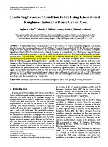
America. The production and use of interlocking concrete block pavers has risen substantially over the past 10 years or so as shown in Figure 1. Interlocking concrete block pavements provide high resistance to freeze-thaw and deicing salts, high abrasion and skid resistance, and protection from petroleum products or deformation/indentations due to high ambient temperatures. Joint sand between the individual concrete pavers facilitates vehicle wheel load transfer and controlled crack locations in order to minimize stress cracking and surface degradation. Concrete pavers are set in bedding sand, which is typically placed over an untreated aggregate base. They can also be placed over bituminous or cement treated base, asphalt concrete, or Portland cement concrete. The spaces between the individual paving units are filled with clean, durable high quality joint sand.
80
72 66
70 60
52
50 34
40 30
40
57
45
28
20 10 0 1998
1999
2000
2001
2002
2003
2004
2005
Year Millions of Square Metres Figure 1. Canadian and U.S. Paver Production – 1998 to 2005. Source: Interlocking Concrete Pavement Institute Currently, there are approximately 80 million square metres of concrete pavers produced annually in North America and 300 million square metres in Europe [1]. Concrete pavers are used successfully in many municipal pavement applications such as parking lots, plazas, city streets, intersections and crosswalks. With the increasing usage of concrete pavers in the municipal setting in North America, and the need for complete asset management, comes the need to assist municipal engineers who either own or are considering interlocking concrete pavements. Many municipal PMS programs incorporate pavement condition evaluation guidelines that follow the U.S. Army Corps of Engineers MicroPAVER distress guide (published by ASTM) to evaluate flexible and rigid pavements. The procedure consists of a methodology to evaluate pavement surface distresses in terms of type, extent and severity and combines this information to develop a standard pavement condition index. While -2-
there has been some research completed to develop methods of evaluating the condition of interlocking concrete pavements (ICP’s), there is no common methodology currently in practice in North America. This paper outlines the procedures used to develop a pavement distress guide for flexible ICP’s following the MicroPAVER protocol.
AN HISTORICAL LOOK AT PAVEMEMT CONDITION RATING SYSTEMS FOR INTERLOCKING CONCRETE PAVEMENTS Over the past 30 years or so, there has been extensive work advancing the theory and practice of the structural design of interlocking concrete block pavements particularly in countries such as Australia, Canada, England, the Netherlands, South Africa and the United States. This has resulted in the increasing use of these types of pavements for municipal applications. With the increasing use of interlocking concrete block pavements, there is a need to expand the focus from design to maintenance and management. Pavement management tools have been developed in Australia [2], Israel [3], the United States [4] and the Netherlands [5], however, much of this work focuses on specific pavement distress types and all recognize that additional work is necessary to come up with an overall pavement condition index. Without a composite condition index, predicting the future pavement condition for use in an overall pavement management system is quite difficult. The Dutch methodology used by the VIAVIEW pavement management system [5] is perhaps the most advanced of the pavement management tools for interlocking concrete block pavements available today. This system, however, is somewhat limited as it considers only rutting and local unevenness as distresses in calculating the composite condition index. The VIAVIEW deterioration model is based on the percentage of equivalent moderate damage with factors used to translate low and severe damage to moderate damage. The percentage of moderate damage is then compared to an established allowable/threshold value of moderate damage to obtain the remaining life of the pavement. While this methodology is relatively sound, it is based on calibration for the Netherlands and extensive performance modeling would be necessary to validate this methodology for use in North America. In a paper by Shackel [2], the development of a pavement management system for concrete block pavements in Australia is discussed. This PMS is based on five primary distress types including rutting, horizontal creep, spalling, cracking and lipping. The paper suggests that while other distresses such as joint width, staining etc. can affect the performance of the pavement, they are insufficiently defined to warrant their inclusion in the pavement management system. In the Australian methodology, the individual distresses are categorized and quantified, multiplied by their individual weight and extent and then summed to determine an overall “deduct” value. This deduct value is then subtracted from 100 to determine an overall pavement condition index (PCI). High PCI values indicate pavements in good condition. A key factor in developing accurate PCI values is in the determination of the values of the individual distress weighting functions
-3-
which can only be done through accelerated testing or pavement performance condition monitoring with time (years). In work completed in 1992 by PCS/LAW Engineering [6], a distress measuring system for interlocking concrete block pavers was created based on the U.S. Army Corps of Engineers MicroPAVER pavement management system. This system was adapted and used by the ICPI for airport pavements as published in the ICPI publication, “Airfield Pavement Design with Concrete Pavers”. The procedure identifies the following interlocking concrete block pavement distresses: • • • • • • • •
Loss of sand in joints; Inconsistent joint widths; Corner or edge spalling; Cracked blocks; Joint seal damage; Disintegration; Depressions/distortions; and Settlement or faulting.
Each distress is identified by type with severity rating ranging from low to high. Suggested remedial action is provided for each distress type and severity. The system does not calculate an overall pavement condition index for the section, but rather, only identifies maintenance treatments. In work completed in Ontario [7], the procedure outlined above was further adapted to develop an overall pavement condition index for interlocking concrete block pavers. The method included the distresses identified by PCS/LAW as well as rutting, pumping and polished aggregates. For each distress, three levels of severity were assigned deduct values based on the type of distress and its expected impact on the overall pavement condition. The density level of distress was not based on individual measurements but rather 5 levels of distress density as follows: • • • • •
Few – up to 5 percent of the surface; Intermittent – up to 15 percent of the surface; Frequent – up to 35 percent of the surface; Extensive - up to 65 percent of the surface; and Throughout – 100 percent of the surface.
The higher the deduct value, the greater the impact that the particular distress, severity and extent has on the overall condition of the pavement. For example, a few extent rating (less than 5 percent of the surface) low severity loss of joint sand would have a deduct value of 3 points resulting in an overall pavement condition index of 100 – 3 = 97. Whereas, frequent (up to 35 percent of the surface) moderate severity rutting (ruts of about 15 to 25 mm) would result in an overall pavement condition index of 100 – 60 = 40. A pavement with a condition index of 40 would represent a pavement in immediate need of rehabilitation. -4-
PCI procedures for asphalt concrete and concrete pavement evaluation were first published by the U. S. Army Construction Engineering Research Laboratory (CERL) in the 1970s for the United States Air Force [8]. Procedures were soon adopted verbatim by the other military branches, the American Public Works Association (APWA) and the Federal Aviation Administration (FAA). Procedures for collecting data and calculating PCI remained unchanged until 1993, when the American Society for Testing and Materials (ASTM) published D5340, “Standard Test Method for Airport Pavement Condition Index Surveys” and D6433, “Standard Test Method for Roads and Parking Lots Pavement Condition Index Surveys”. The PCI guidelines for interlocking concrete block pavements described in this paper are modeled on the U.S. Army Corps of Engineers MicroPAVER distress guide as published by ASTM [9]. The procedures used for completing the condition surveys and calculating the PCI are as per the ASTM procedures. A DIRECTION FORWARD The development of a rational system to determine the condition and provide maintenance and rehabilitation guidelines for interlocking concrete block pavements in North America is considered to be very important in the development of the industry’s drive to expand the municipal market for interlocking concrete block pavements for the following reasons: • •
•
•
Similar pavement evaluation and management tools are already in place for the competing products including gravel, seal coat, flexible and exposed concrete pavements. The pavement maintenance and management tools for gravel, seal coat, flexible and exposed concrete pavements, allow direct one-on-one comparisons of pavement condition through the use of pavement condition parameters such as the PCI. The regular update and tracking of pavement condition through the use of the PCI will permit the development of pavement performance curves (pavement condition versus time) which will assist in the development of appropriate lifecycle cost models for interlocking concrete block pavements. The regular update of the condition of interlocking concrete block pavements through the use of PCI and pavement performance curves will provide the municipal engineers and planner with scientific data showing the benefits of interlocking concrete block pavement.
The pavement management work described above by the Australians, Canadians, Dutch and Americans is the most relevant to assist in developing engineering tools to assist in the life-cycle management of interlocking concrete block pavement. Based on the results of the literature review, the logical sequence to develop the pavement maintenance and management tools is as follows:
-5-
• • • • • •
Develop an interlocking concrete block pavement distress guide. Using the distress guide, develop distress deterioration curves based on the impact of the individual distresses to pavement performance. Develop an overall pavement condition index method for interlocking concrete block pavements. Develop pavement maintenance and rehabilitation trigger values for municipal pavements. Select representative pavement test locations and begin collecting PCI data and validating the methodology. Begin promoting the PCI method at international conferences and through agencies such as the American Public Works Association with the eventual intent of having this method added to ASTM D6433 (Standard Practice for Roads and Parking Lots Pavement Condition Index Surveys).
The following steps were established to develop a MicroPAVER based pavement inspection and rating guideline for interlocking concrete block pavements: • • • • • •
Identify the primary distresses that would affect the performance of interlocking concrete block pavements. Describe how to identify the individual distresses. Determine the method of measurement of the quantity of the distress. Quantify the method of determining the severity of the distress. Establish a deduct curve for each distress type and severity to determine the influence of the distress on the overall condition of the pavement. Establish a means of combining the extent, type and severity of each pavement distress to calculate the overall impact of the distresses on the condition of the pavement and determine and overall pavement condition index for the section.
DISTRESS IDENTIFICATION The MicroPAVER procedure requires the identification of the type of pavement distress, its extent and severity. These values are then used to calculate an overall PCI for the pavement section (Figure 2). The pavement distress, extent and severity are combined using “deduct” curves to establish the impact of the individual distress on the overall condition of the pavement.
-6-
100
Distress Quantity Distress Type
85 70 55 40 25 10 0
PCI Distress Severity
PCI Rating Excellent Very Good Good Fair Poor Very Poor Failed
Figure 2. Flowchart for Determination of PCI. The common distress types for interlocking concrete pavements along with a numerical distress type designation are proposed as follows: 101 102 103 104 105 106 107 108 109 110 111
Damaged Pavers Depressions Edge Restraint Excessive Joint Width Faulting Heave Horizontal Creep Joint Sand Loss/Pumping Missing Pavers Patching Rutting
A detailed description of each of the distresses along with guidelines for the measurement of their extent and severity has been developed in more detail. Each distress is described in terms of low, medium, and high severity level. The proposed criteria and guidelines for each distress type are outlined in the following sections. 101 Damaged Pavers Description: Damaged pavers describe the condition of the paver blocks. Damaged pavers would include paver distresses such as a chip, crack, or spall. Damaged pavers would be indicative of load related damage such as, inadequate support causing shear breakage, etc. Identification: Damaged pavers would include paver distresses such as a chip, crack, or spall. Cracked pavers with little to no opening will not affect performance.
-7-
How to Measure: Damaged pavers are measured in square metres of surface area. Random individual cracked pavers are not counted. The severity is evaluated by degree of distress. Proposed Severity Levels: Severity Level Low Medium High
102
Criteria Individual cracks, spalls, or weathering Advanced cracking, spalling, or weathering Blocks are in multiple pieces or are disintegrated
Depressions
Description: Depressions are areas of the pavement surface that have elevations that are lower than the surrounding areas. Depressions are caused by settlement of the underlying subgrade or granular base. Settlement is common over utility cuts and adjacent to road hardware. Depressions can cause roughness in the pavement, and when filled with water, can cause hydroplaning of vehicles. Identification: Visual examination is not always a reliable technique for detection of depressions, especially for low severity depressions. The most reliably method to identify depressions is to utilize a 3 m straight edge. Changes in shades of color on a pavement surface can give the impression of differential elevation where none exists. The apparent depth of differential elevation is often exaggerated by shadows in the early morning and late afternoon, as well as the chamfer on the paver edges. Standing water and stains can be used to visually identify depressions, however, the boundaries and depth should be established using the straight edge. Be careful to distinguish heaves from depressions. How to Measure: Depressions are measured in square metres of surface area. The maximum depth of depression defines the severity. Depressions larger than 3 m across should be measured with a stringline. Proposed Severity Levels: Severity Level Low Medium High
Maximum Depth of Depression 5 – 15 mm 15 – 30 mm > 30 mm
-8-
103
Edge Restraint
Description: Edge strips and curbing are forms of restraints that provide lateral support for paver pavements. Lateral restraint is considered essential to resist lateral movement, minimize loss of joint and bedding sand, and prevent block rotation. Edge strips/curbs can comprise prefabricated angle supports, concrete curbs, etc. This distress is accelerated by traffic loading. Identification: Loss of lateral restraint is characterized by widening of the paver joints at the outer pavement edge or at the transition of pavement types. Locally pavers at the pavement edge can exhibit both vertical and horizontal rotation as well as local edge settlement. The distress is most notable within 0.3 to 0.6 m of the pavement edge. How to Measure: Loss of edge restraint is measured in linear metres of the movement of the pavement edge restraint from its original position at the pavement edge. Proposed Severity Levels: Severity Level Low
Medium
High
104
Criteria Evidence of increased joint width, (6 – 10 mm) no evidence of paver rotation at curb Increased joint width (11 – 15 mm), with evidence of paver rotation at curb Increased joint width (> 15 mm), with noticeable evidence of paver rotation at curb and local settlement
Excessive Joint Width
Description: Excessive joint width is a surface distress feature in which the joints between blocks have widened. Excessive joint width can occur from a number of factors including; poor initial construction, lack of joint sand, poor edge restraint, adjacent settlement/heave, etc. As joints get wider, the block layer becomes less stiff and can lead to overstressing the substructure layers. Identification: Optimal block spacing is typically specified as 2 to 5 mm. As joints get wider, the individual blocks may show signs of rotation. How to Measure: Excessive joint width is measured in square metres of surface area. The average joint widening defines the severity. As concrete pavers are manufactured with a beveled edge, care must be taken to ensure the actual joint width is measured.
-9-
Proposed Severity Levels: Severity Level Low Medium High 105
Average Joint Width 6 – 10 mm 11 – 15 mm > 15 mm
Faulting
Description: Faulting are areas of the pavement surface where the elevation of adjacent blocks differ or have rotated. Faulting can be caused by surficial settlement of the bedding sand, poor installation, pumping of the joint or bedding sand. Local roughness can reduce the ride quality. Faulting can be corrected by resetting the blocks. Identification: Faulting is characterized by small areas of individual blocks standing proud of each. This distress is often associated with more severe distresses such as settlement, heave, rutting, etc. How to Measure: Faulting is measured in square metres of surface area. The maximum elevation difference defines the severity. Proposed Severity Levels: Severity Level Low Medium High
Elevation Difference 4 – 6 mm 6 – 10 mm > 10 mm
It should be noted that excessive faulting of the blocks can represent a pedestrian trip hazard particularly in cross walk areas. 106
Heaves
Description: Heaves are areas of the pavement surface that have elevations that are higher than the surrounding areas. Heaves are typically caused by differential frost heave of the underlying soils. Heaves can also occur as a result of subgrade instability and can also occur in conjunction with settlement/rutting. Identification: Visual examination is not always a reliable technique for detection of heaves, especially for low severity depressions. The most reliably method to identify heaves is to utilize a 3 m straight edge. How to Measure: Heaves are measured in square metres of surface area. The maximum height of heave defines the severity. Heaves larger than 3 m across should be measured with a stringline.
- 10 -
Proposed Severity Levels: Severity Level Low Medium High
107
Maximum Height of Heave 5 – 15 mm 15 – 30 mm > 30 mm
Horizontal Creep/Shoving
Description: Horizontal creep, or shoving, is the longitudinal displacement of the pavement caused by traffic loading. Identification: Regardless of the block bond, the pavement surface should have a uniform pattern. Shifting of the joints or pattern signify horizontal creep. How to Measure: Horizontal creep, or shoving, is measured in square metres of surface area. The deviation from the original position defines the severity. Proposed Severity Levels: Severity Level Low Medium High 108
Horizontal Movement 6 – 10 mm 11 – 20 mm > 20 mm
Joint Sand Loss/Pumping
Description: Joint sand loss is a distress feature in which the joint has been removed. Joint sand loss can occur from a number of factors including; heavy rain, sweeping, pressure washing, pumping under traffic loading, etc. Joint sand is considered essential to providing interlock and stiffness of the paver course. How to Measure: Joint sand loss/pumping is measured in square metres of surface area. The depth of sand loss defines the severity. As concrete pavers are manufactured with a beveled edge, care must be taken to ensure that the measurement is from the bottom of the chamfer downwards into the joint with a blunt edged measuring tool. Proposed Severity Levels: Severity Level Low Medium High
Depth of Sand Loss 5 – 10 mm 11 – 25 mm > 25 mm
- 11 -
109
Missing Pavers
Description: Missing pavers, as the name implies, refers to sections of pavement that are missing pavers, that may have resulted from removal or disintegration/damage. Missing pavers can compromise the integrity of the pavement structure and promote surface roughness similar to potholes in flexible pavements. Identification: Sections that are missing pavers. How to Measure: Missing pavers are measured in square metres of surface area. The severity is evaluated by degree of distress. Random individual paver damage would not be counted. Proposed Severity Levels: Severity Level Low Medium
High
110
Criteria Random individual missing pavers. Missing (2 or more) multiple pavers (in one area) and ride quality unaffected. Missing (2 or more) multiple pavers and ride quality affected.
Patching
Description: Patching refers to sections of pavement that are missing pavers and have been reinstated with a dissimilar material. Patch quality can compromise the integrity of the pavement structure and promote surface roughness similar to potholes in flexible pavements. Identification: Sections of dissimilar materials such as asphalt, etc. . How to Measure: Patches are measured in square metres of surface area. The severity is evaluated by the quality of the patch. Proposed Severity Levels: Severity Level Low Medium
High
Patch is in good condition and ride quality is unaffected. Patch is in good to fair condition and ride quality is starting to deteriorate. Patch is in poor condition and ride quality is affected.
- 12 -
111
Rutting
Description: Rutting is a surface depression in the wheel path. Depressions are areas of the pavement surface that have elevations that are lower than the surrounding areas. Rutting is typically caused by settlement of the underlying subgrade or granular base under vehicle loading. Depressions can cause roughness in the pavement and, when filled with water, can cause hydroplaning of vehicles. Identification: Locate rutting by visual assessment and measure rutting with a straight edge. Rutting in a single wheel path is usually quite evident. However, depressions caused by static wheel loads are measured as rutting. How to Measure: Rutting is measured in square metres of surface area. The maximum rut depth defines the severity. To determine the rut depth, a straight edge should be placed across the rut and the depth measured in millimetres. Rut depth measurements should be taken along the length of the rut. Varying severities of rutting along the length of the rut should be measured individually. Proposed Severity Levels: Severity Level Low Medium High
Maximum Depth of Rut 5 – 15 mm 15 – 30 mm > 30 mm
An example field condition evaluation form is shown in Figure 3.
- 13 -
INTERLOCKING CONCRETE BLOCK ROADS AND PARKING LOTS CONDITION SURVEY DATA SHEET FOR SAMPLE UNIT ROAD __________________________________________________________DATE______________ SECTION______________________________________________________ SAMPLE UNIT_______ SURVEYED BY ___________________________
SAMPLE AREA (sq m) ________
DISTRESS NUMBER AND TYPE 101 104 107 110
Damaged Pavers Excessive Joint Width Horizontal Creep Patches
DISTRESS/ SEVERITY
102 105 108 111
Depressions Faulting Joint Sand Loss/Pumping Rutting
QUANTITY
103 Edge Restraint 106 Heave 109 Missing Pavers
TOTAL
DENSITY %
DEDUCT VALUE
SKETCH
NOTES:________________________________________________________________ ________________________________________________________________________ ________________________________________________________________________ Figure 3. Example Interlocking Concrete Block Pavement PCI Field Form
- 14 -
DISTRESS GUIDE PHOTOGRAPHS AND DEDUCT CURVES In order to assist field surveyors in the identification and assessment of interlocking concrete block pavement distresses, the interlocking concrete block pavement distress guide includes photographs of typical distresses and their severity levels. Examples of the distress guide photographs for excessive joint width are shown in Figures 4 to 6. The distress guide contains similar photographs for each of the identified distresses.
Figure 4. Low Severity Excessive Joint Width. (less than 6 mm wide with or without joint sand loss and performing well)
Figure 5. Medium Severity Excessive Joint Width.
- 15 -
Figure 6. High Severity Excessive Joint Width. (greater than 10 mm with loss of joint sand and misalignment) CALCULATION OF DEDUCT VALUE The deduct value for an individual distress is determined by entering the distress extent in terms of a distress density (measured distress area divided by the total area of the pavement area being inspected) and the distress severity and determining the deduct value from a curve similar to that shown in Figure 7. EXCESSIVE JOINT WIDTH
PAVERS 104
100 90 80
H DEDUCT VALUE
70 60 50
M
40 30
L
20 10 0 0.1
1
10 DISTRESS DENSITY (%)
Figure 7. Deduct Curve for Excessive Joint Width. - 16 -
100
Similar deduct curves were developed for each distress type and severity based on engineering experience and input from the industry. It is intended to validate these distress curves as a part of a field evaluation to take place in 2007. CONCLUSIONS The information outlined in this paper combined with the PCI calculation methodology standardized by ASTM outlines the proposed methodology and tools for the pavement practitioner to objectively evaluate the condition of interlocking concrete block pavements. The intent is to establish an overall pavement condition and monitor that condition for pavement management and pavement maintenance management purposes. Field evaluation will be completed in 2007 to validate the severity distress levels and the accompanying distress curves. REFERENCES 1.
Interlocking Concrete Block Paving Institute, www.icpi.org, Washington, D.C.
2.
Shackel, B., Pearson, A., and Vella, A., Progress Towards a Maintenance Management System for Concrete Block Pavement in Australia, Third International Workshop on Concrete Block Paving, Columbia, May 1998.
3.
Geller, R., Concrete Block Paving Condition Survey and Rating Procedures, Pave Israel, Tel Aviv, Israel, 1996.
4.
Stephanos, P.J. and Rada, G.D., Guideline for Defining Visual Distress in Interlocking Concrete Pavements, PCS/LAW Engineering, January 1992.
5.
The Netherlands Centre for Research and Contract Standardization in Civil and Traffic Engineering, Pavement Management System, C.R.O.W., 1993.
6.
Rada, G.R., Stephanos, P.J. and Tayabji, S.D., Performance of Interlocking Pavements in North America, National Research Council, Washington, D.C., 1993.
7.
IPCI, Life-Cycle Cost Analysis – Interlocking Concrete Pavements, John Emery Geotechnical Engineering Limited, March 2000.
8.
Shahin, M.Y., Pavement Management for Airports, Roads and Parking Lots, Chapman & Hall, 1994.
9.
ASTM, Annual Book of ASTM Standards, Section 4, Construction, ISBN 0-803127758-8, Washington, D.C.
- 17 -