World Electric Vehicle Journal Vol. 7 - ISSN 2032-6653 - ©2015 WEVA
Page WEVJ7-0166
EVS28 KINTEX, Korea, May 3-6, 2015
Development of a Plug-In HEV Based on Novel Compound Power-Split Transmission Tong Zhang1, Chen Wang1,2, Zhiguo Zhao2, Wentai Zhou1,2 1
Corun CHS Technology Co., Ltd., NO.2888 Wanfeng Road, Fenjing Industry Park, Jinshan District Shanghai 201501, China 2 Clean Energy Automotive Engineering Center, Tongji University, N0.4800 Caoan Road, Jiading District, Shanghai 201804, China,
[email protected]
Abstract In order to extend the product applications into plug-in hybrid electric vehicle field, a high capacity lithium-ion battery is configured and matched to the previous compound power-split hybrid transmission which is based on a modified ravigneaux gear set with two additional brake clutches. The equivalent lever diagrams are used to investigate the operating modes for the hybrid system, and its dynamic and kinematic characteristics in equations are derived. To evaluate the economy and power performance of the plug-in hybrid vehicle, a forward-looking simulation platform and components model are established. In addition, the simulating results of key power and economy tests are demonstrated. Results show that the proposed powertrain configuration can be well used for plug-in applications, and the economy and power performance can be further improved. Keywords: PHEV, Hybrid Transmission, E-CVT, Ravigneaux Gear Set
1
Introduction
The class of plug-in hybrid electric vehicle (PHEV), where the power battery with high capacity can be recharged from an external source, dramatically improved the vehicle economy and emission performance. Several powertrain configurations, including series, parallel, and power-split were selected with respect to component sizes and fuel economy for PHEV applications. It is complex to decide the optimal powertrain configuration for PHEV applications. But in the charging depletion mode, the power-split provided the best fuel economy as a result of its dual path of power from the engine to the wheel [1]. The GM volt hybrid powertrain [2] based on a output power-split device was originally designed for PHEV application. The TOYOTA
prius plug-in hybrid powertrain [3] was developed based on the third generation toyota hybrid system (THS) with an input power-split device. In this paper, we develop a plug-in hybrid powertrain on the basis of previous strong hybrid powertrain equipped with a novel compound power-split device. A high capacity lithium-ion battery is substituted for the nickel-metal battery to extend the electric driving range. In addition, different operating modes are analysed using lever diagrams, and the control strategy which slightly modified to take well use of the grid power is presented. Furthermore, the power and economy simulation tests are applied to validate the effectiveness of concept design and control strategy.
EVS28 International Electric Vehicle Symposium and Exhibition
1
World Electric Vehicle Journal Vol. 7 - ISSN 2032-6653 - ©2015 WEVA
2
Hybrid Powertrain
2.1
Mechanism Description
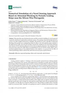
The compound power-split device [4] comprises the two planetary gear trains (PGTs) that share the carrier and ring gear, as shown in figure 1. The schematic diagram of the hybrid powertrain and corresponding lever diagram are shown in figures 2 and figure 3, respectively.
Page WEVJ7-0167
The small sun gear of the front planetary gear train is connected to the motor MG1, which can be held stationary by the brake clutch B2. The big sun gear of the rear planetary gear train is connected to motor MG2 and the output ring gear (OUT) is connected to the final reduction gear. S1(MG1)
C1(ENG) R1(OUT) S2(MG2) ωS2 ωC1=0
R1
P2
P1
R1
P2
ρ1
S2 P1
C1
S1
S1
ωR1 1
ρ2 - 1
ωS1
S2
Figure 3: Lever diagram C1
Figure 1: Schematic of compound power-split device.
In figure 1, the small sun gear S1 of the front PGT is meshed with the short and thick planet gear P1, which directly engages with the ring gear R1. The large sun gear S2 of the rear PGT is meshed with the long and thin planet gear P2, which engages with planet gear P1 of the front PGT. The front and rear PGTs share the planet carrier C1 and ring gear R1. OUT
B1
MG2
In Figure 3, ωS1, ωS2, ωR1, and ωC1 are the angular velocities of S1, S2, R1, and C1, respectively; ρ1 is the gear ratio of the front PGT given by ρ1 = ZR1⁄ZS1 = R1⁄S1; ρ2 is the gear ratio of the rear PGT given by ρ2 = ZR1⁄ZS2 = R1⁄S2; ZS1, ZS2, and ZR1 are the tooth numbers of S1, S2, and R1, respectively; and S1, S2, and R1 are the radius of S1, S2, and R1, respectively. The relevant vehicle and components parameters are listed in table 1. Economy simulation tests are carried out by considering 100 kg in addition to the vehicle kerb mass whereas 395 kg additional mass for power performance simulation tests.
MG1 B2
ENG
TSD
Figure 2: Schematic of the hybrid powertrain
Figure 2 shows a schematic diagram of a hybrid powertrain based on the compound power-split device. The powertrain is made up of compact dual planetary gear trains integrated with two electric motors that can also function as generators. The two groups of planet gears are connected together by a common carrier shaft that is attached to the crankshaft of engine through a torsional spring damper. The carrier is grounded to the housing by the brake clutch B1.
Table 1: Vehicle and components parameters
Parameter Kerb mass (kg) Wheel radius (m) Road law coefficient Drag coefficient Frontal Area (m2) Final reduction gear ratio
ρ1 ρ2 ENG rated power (kw) ENG max torque (Nm) MG1 rated power (kw) MG1 max torque (Nm) MG2 rated power (kw) MG2 max torque (Nm) Battery rated capacity (Ah) Battery rated voltage (V)
2.2
Value 1530 0.32 0.0085 0.307 2.19 4.092 3.174 2.355 98 170 44 93 65 246 37 307
Dynamics and Kinematics
Ignoring the moment of inertia of all the planet gears, the kinetic and kinematic expression of each shaft of the compound power-split device based on
EVS28 International Electric Vehicle Symposium and Exhibition
2
World Electric Vehicle Journal Vol. 7 - ISSN 2032-6653 - ©2015 WEVA
Page WEVJ7-0168
the speed, torque, and gear meshing force relationship of the components in the compound power-split device is given by [5].
is final reduction gear ratio; and R is the radius of the wheel.
S1 1 C1 M R1 S2
3
TC1 1 TS1 T N T R1 S2
The electric operating mode with B1 engagement should be given a priority once there is no requirement for mode transition and no failures in the hydraulic system. The vehicle can be selectively driven by single motor or two motors. The driving torque can be provided independently by MG1 or MG2 to overcome the OUT resistance torque while the other motor spins freely. We can use two motors to drive the vehicle simultaneously for better power performance. The lever diagram of electric operating modes with B1 engagement is demonstrated in figure 3.
where
2 1 2 M 1 1 1 2
1 1 2 2 1 1 2
2 1 2 N 1 1 2
1 2 1 2 1 1 1 2
TC1 is the torque applied on the carrier shaft by the front and rear PGTs, TR1 is the torque applied on the ring gear shaft by the front and rear PGTs, TS1 and TS2 are the torque applied on the small and large sun gear shaft. Ignoring the moment of inertia of all planet gears, the gap and mesh elasticity between each gear, the influence of the torsional spring damper, and considering the equivalent friction damping loss of each shaft, the kinetic and kinematic expressions of each shaft of the hybrid transmission are given by:
I ENG I C1 ENG TC1 bENGENG TENG
mR2 K 2 I R1 OUT TR1 bOUTOUT Tf I MG1 IS1 MG1 TS1 bMG1MG1 TMG1 I MG2 IS2 MG2 TS2 bMG2MG2 TMG2 where IENG, IMG1, IMG2, IC1, IR1, IS1, IS2 are the moments of inertia of the ENG, MG1, MG2, C1, R1, S1, and S2 shafts, respectively; ωENG, ωOUT, ωMG1, and ωMG2, are the angular velocities of the ENG, OUT, MG1, and MG2 shafts, respectively; bENG, bOUT, bMG1, and bMG2 are the equivalent damping coefficients of the ENG, OUT, MG1, and MG2 shafts, respectively; TENG, TMG1, and TMG2 are the output torques of the ENG, MG1, and MG2, respectively; Tf is the resistance torque of the OUT shaft; m is the mass of the vehicle; K
Operating Mode
3.1
Electric Mode
S1 MG1
B2
C ICE
R OUT
S2 MG2
B1
Figure 3: Lever diagram of electric operating mode
3.2
Power-Split Hybrid Mode
Once the capacity of power battery is insufficient during the medium or high speed driving, the system switches to the power-split hybrid mode because of the high efficiency between the two mechanical points [6] of this compound powersplit system. In this mode, the vehicle is mainly powered by the engine while the MG1 regulates the engine operating point and battery charging power and the MG2 recuperates the vehicle inertia energy or assists the engine to drive the vehicle. The lever diagram of this power-split hybrid operating mode is demonstrated in figure 4.
3.1
Fixed Gear Hybrid Mode
We utilize another hybrid operating mode with fixed gear ratio to overcome the low efficiency of MG1 among an overdrive driving range. In this mode, the vehicle can be driven by engine independently whereas the MG1 be shut off. The
EVS28 International Electric Vehicle Symposium and Exhibition
3
World Electric Vehicle Journal Vol. 7 - ISSN 2032-6653 - ©2015 WEVA
balance torque in the small sun gear shaft is provided by B2 whereas the MG2 gives torque assistance to drive or brake the vehicle. The lever diagram of the fixed gear hybrid operating mode is showed in figure 5. S1 MG1
R C ICE OUT
S2 MG2
Page WEVJ7-0169
speed, 0-100 km/h acceleration ability in electric driving mode or hybrid driving mode, 50-80 km/h and 60-90 km/h acceleration ability, and the grade ability, economic testing includes range test under altered NEDC driving cycle, energy consumption test according to the standard GB/T 17953-2013 [7]. Simulation results are summarized in table 2. Table 2: Power and economic performance
B2
B1
Figure 4: Lever diagram of power-split hybrid mode S1 MG1
R C ICE OUT
S2 MG2
Item Max EV speed (km/h) 0-50 km/h EV acceleration time (s) 0-90 km/h EV acceleration time (s) 50-80 km/h EV acceleration time (s) EV grade ability (%) Max HEV speed (km/h) 0-50 km/h HEV acceleration time (s) 60-100 km/h HEV acceleration time (s) 0-100 km/h HEV acceleration time (s) HEV grade ability (%) Fuel consumption (L/100 km) Electric consumption ( kWh/100km )
4.1
B2
B1
Figure 5: Lever diagram of fixed gear hybrid mode
4
Simulation
In this section, the effectiveness of powertrain configuration and control strategy is discussed with respect to a simulation validation for power and economy performance. Before simulating, some assumptions are given as follows: The maximum discharge power is given by a constant value of 75 kW. Only 20% of whole braking torque can be implemented by regenerative braking, no matter how fast the vehicle speed is. The internal resistance of power battery is given by a constant value of 1.5 mΩ. The max speed of MG1, MG2, and ENG is 10000, 8000, and 5500 rpm, respectively. Simulations includes power testing and economy testing, in which power testing includes max
Value 90 4.52 11.58 4.93 30 185 4.6 3.7 9.3 30 2.9 6.4
Power Performance
As shown in figure 6 and figure 7, the acceleration time from 0 to 50 km/h and 0 to 90 km/h is 4.52 s and 11.58 s, respectively. The vehicle is propelled by the MG1, MG2 whereas the B1 provides plus brake torque to balance the lever. The maximum EV speed is limited to 90 km/h because of the maximum operating speed of MG1. In figure 8 and figure 9, the acceleration time in the medium driving range from 50 to 80 km/h is 4.93 s, the acceleration ability declines because of the limited MG2 torque. As torque requirement on the output shaft increases, the brake torque of B1 rises up. Considering the weakness of acceleration ability in pure electric driving mode, we start the engine in the medium speed to enhance driving torque on the output shaft, as well as supply additional driving power to wheel. As shown in figure 10 and figure 11, the B1 is released at 2.6 s while MG1 is similar to pure electric driving mode except for the release of additional dragging torque to overcome the engine brake torque and for rapid engine crank in order to get to the target operation speed. The vehicle speed slows down whereas the torque of MG2 declines to guarantee the acceleration of engine shaft. Fuel is injected and ignited once the engine is running stably at a fixed speed range. Following that, the engine ensures quick torque response to guarantee the requirements that is the output characteristic of engine sent by the upper lever control unit.
EVS28 International Electric Vehicle Symposium and Exhibition
4
Speed (km/h)
100 50 0 0
2
4
6
8
10 TOUT
400
T
B1
200 4
6
8
10
2 1 0 0
2
4
6 Time (s)
8
10
14
15
16
9
10
11
12
13
14
15
16
0 -50 8
0 0
2
4
6
8
10
0 0
Torque (Nm)
100 0 -100 0
2
4
6
8
10
9
10
11
12 13 Time (s)
14
15
16
2
4
6
8
10
6
8
10
-1 0
2
4
6 Time (s)
8
10
6
8
10
100 0 0
2
4
12
5000 4000 3000 2000 1000 0 0
2
4
Speed (rpm)
MG1 MG2
0
200
12
x 10
Time (s)
Speed (km/h)
Figure 10: ENG points of 0-100 km/h HEV acceleration
9
10
11
12
13
14
15
T
100
TB1 16
250 200 150 100 50 0 0
OUT
9
10
11
12
13
14
15
50 0 0
Torque (Nm)
200
100
16
300
3
2
4
6
8
10
6
8
10
6
8
10
MG1 MG2
2
4
2
4
Speed (rpm)
10000
2 1 0 8
-1 8
300
200
0 8
MG1 MG2
0
50
12
300
90 80 70 60 50 40 8
1
x 10
100
Speed (km/h)
Speed (km/h)
50
speed (rpm)
13
Figure 9: MG points of 50-80 km/h EV acceleration
100
Speed (km/h)
12
50
400
(Nm)
11
100
12
Figure 7: MG points of 0-90 km/h EV acceleration
OUT
10
4
3
1
9
150
12
4
T
40 8
4
Figure 6: 0-90 km/h EV acceleration ability
Acceleration (m/s2)
60
speed (rpm)
Acceleration (m/s2)
2
80
12
600
0 0
Torque (Nm)
Page WEVJ7-0170
Torque (Nm)
Torque (Nm)
Speed (km/h)
World Electric Vehicle Journal Vol. 7 - ISSN 2032-6653 - ©2015 WEVA
9
10
11
12 13 Time (s)
14
15
0 -5000 0
16
Figure 8: 50-80 km/h EV acceleration ability
5000
Time (s)
Figure 11: MG points of 0-100 km/h HEV acceleration
EVS28 International Electric Vehicle Symposium and Exhibition
5
World Electric Vehicle Journal Vol. 7 - ISSN 2032-6653 - ©2015 WEVA
Page WEVJ7-0171
The maximum vehicle speed in hybrid driving mode is limited to 185 km/h because of the maximum operating speed of MG2 and ENG. The grade ability for pure electric or hybrid driving mode is above 30 % and the acceleration time in the medium driving range from 60 to 100 km/h is 3.7 s,
consumption of 7.37 kWh. It is noticeable that the little regenerative braking is implemented because of the limited braking requirement under altered NEDC driving cycle and fixed distribution of braking torque derived from the former assumption. Secondly, the weighted mean value for fuel consumption and electric energy consumption are calculated as follows:
4.2
C
Economy Performance
According to the test method for energy consumption of light-duty hybrid electric vehicle, the electric driving range simulation test under altered NEDC driving cycle which the maximum speed is limited to 90 km/h with a full charged power battery is implemented firstly. Simulation results are summarized in figure12 and figure 13.
50 0 0
1000
2000
3000
4000
5000
6000
7000
1000
2000
3000
4000
5000
6000
7000
1
SOC (/)
0.8 0.6 0.4
Distance (Km)
0.2 0 60
20 0 0
1000
2000
3000 4000 Time (s)
5000
6000
7000
0
Power (kW)
-10 -20 -30 0
1000
2000
3000
4000
5000
6000
7000
0 -50 -100 0
1000
2000
3000 4000 Time (s)
5000
6000
7000
10
Actual Expect
50 0 0
200
400
600
800
1000
1200
200
400
600
800
1000
1200
200
400
600 Time (s)
800
1000
1200
2 1.5 1 0.5 0 0 6 4 2 0 0
Figure 13: NEDC test with full charged power battery
5 0 0
100
Energy (Kwh)
Current (A)
(2)
40
Figure 12: Altered NEDC driving cycle range test
Quantity (kWh)
(1)
where C and E are fuel consumption weighted mean value (L/100 km) and electric energy consumption weighted mean value (kWh/100 km); De is the electric driving range (km); Dav is an assumption driving range of 25 km for two battery charging activities; c1 and E1 are the actual fuel consumption (L/100 km) and electric energy consumption (Wh/km) under NEDC driving cycle with a full charged power battery; c2 and E4 are the actual fuel consumption and electric energy consumption under NEDC driving cycle with a depletion power battery. The NEDC simulation results of a vehicle with a full charged power battery and a depleted power battery are demonstrated in figure 13 and figure 14. Fuel Consumption (L/100km)Speed (km/h)
Speed (km/h)
100
De c1 Dav c2 De Dav D E Dav E4 E e 1 De Dav
1000
2000
3000 4000 Time (s)
5000
6000
7000
Figure 13: Electric consumption of rang test
As shown in figure 12 and figure 13, the vehicle can be driven for 51.7 km with an electric energy
In figure 13, we use the electric energy to drive the vehicle, referred to charge depletion mode. The vehicle will not start the engine until the vehicle speed reaches 90 km/h or the battery status of charge drops to a pre-set low threshold. After that, the vehicle is powered by engine and motors together like a conventional HEV, and the battery status of charge maintains at a vicinity of the pre-
EVS28 International Electric Vehicle Symposium and Exhibition
6
World Electric Vehicle Journal Vol. 7 - ISSN 2032-6653 - ©2015 WEVA
Energy (Kwh) Speed (km/h) Fuel Consumption (L/100km)
set threshold. The fuel consumption of this test is 1.75 L/100 km while the electric energy consumption is 97.9 Wh/km. 100
Actual Expect
50 0 0
200
400
600
800
1000
1200
6 4
Page WEVJ7-0172
References [1]
[2] N. Kim, J. Kwon and A. Rousseau, Comparison of Powertrain Configuration Options for Plug-in HEVs from a Fuel Economy Perspective, SAE paper 2012-01-1027, 2012. [3]
C. Ma, J. Kang, W. Choi, et al., A comparative study on the power characteristics and control strategies for plug-in hybrid electric vehicles, International Journal of Automotive Technology, 13(3) , pp.505-516, 2012.
[4]
T. Zhang, W. Yu, Z. T. Ma, et al., Double planetary row four-axis transmission. Chinese Patent CN102022489 A, China, 2011.
[5]
C. Wang, Z. G. Zhao and T. Zhang, et al., Development of a compact compound power-split hybrid transmission based on altered Ravigneaux gear set, SAE paper 2014-01-1793, 2014.
[6]
J. Kim, J. Kang and Y. Kim, et al., Design of power split transmission: Design of dual mode power split transmission, International Journal of Automotive Technology, 11(4) , pp.565-571, 2010.
[7]
GB/T 19753-2013. Test methods for energy consumption of light-duty hybrid electric vehicles, Chinese Standard GB/T, Beijing, 2013.
2 0 0
200
400
600
800
1000
1200
1
0.5 0
-0.5 0
200
400
600 Time (s)
800
1000
1200
Figure 14: NEDC test with depleted power battery
As shown in figure 14, the vehicle works in the charge sustaining mode. The engine automatic stop and re-start is scheduled during the whole driving cycle. The electric energy consumption is almost zero while the fuel consumption is 5.3L/ 100 km. According to the equation 1 and equation 2, the weighted mean values of fuel consumption and electric energy consumption are 2.9 L/100 km and 6.4 kWh/100 km respectively.
5
V. Freyermuth, E. Fallas and A. Rousseau, Comparison of Powertrain Configuration for Plugin HEVs from a Fuel Economy Perspective, SAE paper 2008-01-0461, 2014.
Authors
Conclusion
The previous strong hybrid powertrain equipped with a novel compound power-split device can be well extended into PHEV applications. The economy performance is acceptable whereas the power performance is not quite satisfactory. Especially, the maximum electric driving speed is limited to 90 km/h and the electric acceleration ability is insufficient. Future works aim to overcome above shortages and enhance the system efficiency in the electric driving mode by using an additional clutch located between the engine and carrier shaft.
Acknowledgments
Tong Zhang, Chief Technology Offier, Ph.D, Corun CHS Technology Co., Ltd., NO.2888 Wanfeng Road, Fenjing Industry Park, Jinshan District Shanghai 201501, China Phone: +86 021-51211999-8686
[email protected]
Chen Wang, Ph.D Candidates, Clean Energy Automotive Engineering Center/School of Automotive Studies, Tongji University, Shanghai 201804 Phone: +86 021-51211999-8712
[email protected]
This work was supported by The National High Technology Research and Development Program of China (No. 2011AA11A207) and National Natural Science Foundation of China (No. 51275355).
EVS28 International Electric Vehicle Symposium and Exhibition
7