Hindawi Publishing Corporation Journal of Industrial Engineering Volume 2016, Article ID 8431893, 8 pages http://dx.doi.org/10.1155/2016/8431893
Research Article Development of a Pneumatically Driven Cell for Low Cost Automation Antonio Carlos Valdiero, Ivan Jr. Mantovani, Andrei Fiegenbaum, Giovani P. B. Dambroz, and Luiz A. Rasia Exact Sciences and Engineering Department, Regional University of Northwestern Rio Grande do Sul State (UNIJUI), Av. Rudi Franke 540, P.O. Box 121, 98280-000 Panambi, RS, Brazil Correspondence should be addressed to Antonio Carlos Valdiero;
[email protected] Received 16 June 2016; Accepted 24 August 2016 Academic Editor: Gabor Szederkenyi Copyright © 2016 Antonio Carlos Valdiero et al. This is an open access article distributed under the Creative Commons Attribution License, which permits unrestricted use, distribution, and reproduction in any medium, provided the original work is properly cited. The present work addresses the development of a pneumatically driven manufacturing cell for low cost automation applications. This cell can be used in innovative applications as a low cost alternative to increase production and quality in industry. The state of the art shows that technological advances in computing have made possible a drop in equipment prices, making them more accessible. The aim of this work is to develop automation through a classic methodology for a manufacturing cell to minimize errors and facilitate the sequential logic conception. This experimental prototype has been developed at the UNIJUI with financial support by public organizations and companies. Pneumatic actuator used in bench driven has the following advantages: its maintenance is easy and simple, is of relatively low cost, self-cooling properties, and good power density (power/dimension rate), and is fast acting with high acceleration and installation flexibility. However, there are difficulties of control logic due to the complex systems. The sequential controller strategy design considers the pneumatic system, experimental results, and performance of the proposed control strategy.
1. Introduction The present work addresses the development of a pneumatically driven manufacturing cell for low cost automation applications when compared with other high-cost automation technologies such as pneumatic servo position applications [1–5]; for example, Festo has an industrial pneumatic servo solution in the delivery range being very efficient but however expensive [6]. In our current society, the capacity of performing tasks with higher efficiency and precision is increasingly sought by automation [7]. In this way, the productive systems must ensure competency, considering a market that is increasingly more demanding and competitive [8]. The main advantages of automation are the replacement of the manual operations, increased productivity, decreased cost, and more consistent and uniform final product [9]. It is in that scenario that the pneumatic systems application on industrial automation has stood out, due to its simplicity and low cost of its basic components [10]. With the introduction of solenoid actuated valves, relays and their digital command techniques started to be used, in
order to achieve the logic of the command system signals. This combination of technical resources from pneumatics, microelectronics, and informatics is called pneutronics [10], which is an analogy to mechatronics, a harmonious integration of mechanical and electronic engineering and computer controlling. In Figure 1, there is a generic representation of a mechatronic system, showing the interaction between sensors, controlling system, and actuators [9]. Having that in view, this paper describes the automation system development with pneumatic actuation to feed, fix, and remove a part after a given operation. Posteriorly, the employed methodology to conceive the system functioning will be presented, showing the techniques and methods utilized, the results obtained, and the final conclusions.
2. Methodology As quoted, with the advances of pneumatics, aided by electronics, the construction of high complexity systems becomes viable. For that, scientific methodologies are used for each type of project. For this paper, a project of sequential logic
2
Journal of Industrial Engineering
Mechanical system
Actuators
Sensor
Actions
Information
Digital processing
Figure 1: General representation of a mechatronic system. Path-step diagram Components Designation Notation
A
B
C
State
Temp Step 1
D
2
3
E F
4
5
6
7
G
Figure 2: Typical path-step diagram form [10].
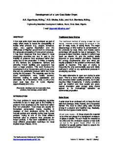
will be discussed, which begins by the verbal description of the problem, to the formulation of graphic diagrams, whereas the diagrams minimize errors and make programming easier. Two types of graphic representation were used, for the presented problem’s sequential command, a pathstep diagram (PSD) and a functional diagram (FD), followed by a microprocessor platform programming. These steps are described as follows.
and G are subdivided as columns according to the number of sequential steps, where E eventually indicates the step time and F shows the beginning and end of each step, since the G field represents the status of each cylinder of the sequential command. Field A only lists the rows. This method is used traditionally in electropneumatics, for being easy to elaborate and representing the pneumatics cylinders’ sequential commands sufficiently well.
2.1. Elaboration of the Path-Step Diagram (PSD). According to [10], the path-step diagram (PSD) represents the position of the pneumatic cylinder’s piston rods, extended or retracted, being applied to every step of the sequential command. For each pneumatic cylinder, a line is set, where the logic is inserted on the “state” column, which can be extended on the upper part and retracted on the lower part or an inverted logic. The transition of a step to the other is given by the extension/retraction of a pneumatic cylinder’s piston rod or through external signals. In agreement with [10], fields B, C, and D of Figure 2 describe the pneumatic cylinders that compose the system, whereas they inform, respectively, the type of cylinder, the notation, and the adopted convention to identify the state of the piston rod as extended or retracted. Fields E, F,
2.2. Elaboration of the Functional Diagram (FD). As stated by [10], the functional diagram, also known as operation scheme, represents the sequential command divided by steps, the actions associated with each step, and the logical conditions related to the transition of each step. Figure 3 presents the basic set of rectangles that feature a step of a sequential command, according to the DIN 40719-6 standard, where (a) indicates the identification number of the step and, optionally, a brief description of it, (b) indicates some signal property that creates the action, (c) designates the action, (d) indicates the signal element that confirms the fulfillment of the action, and (e) indicates logical condition associated with the transition of a step to the next one. As stated in [10], it is still important to consider that the functional diagram refers to the sequential command as a
Journal of Industrial Engineering
3
(a) I1 I2
(e) &
(a)
(b)
(c)
(d)
(a)
Figure 3: Basic block of the functional diagram, in agreement with the DIN 40719-6 standard [10].
whole, that is, to the signal processing and to the commanded actions by the signals originated from this processing. 2.3. Implementation in the Microprocessor Platform. The system sequencing graphic diagram is necessary to program the steps of the sequential command into a device that receives the data, processes them, and acts on the system according to the preestablished parameters; for the solution of this paper, an Arduino microprocessor platform that utilizes a programming language similar to C/C++, with some specific commands, will be used. According to [11], the biggest advantage of Arduino over other microprocessor development platforms is the easiness of use, where people that are not on its technical field can, quickly, learn the basics and create their own projects in a relatively short time period. Arduino microcontrollers are already established for use in low cost high-quality scientific and engineering equipment [12, 13]. Still, mentioned by [14], the Arduino’s IDE open software is used to program, where we write the codes, and it allows you to write a computer program (sketches), which are a set of instructions, step by step; then we can load the program to the Arduino platform, an then, it will execute these instructions to whatever is connected to it.
3. Results and Discussion As a result, a pneumatically driven manufacturing cell prototype was built and tested as shown in Figure 4(b). The tests were performed using a wooden parts box, where the last step provides the fixation of the wooden part to a possible manufacturing operation (such as drilling and milling). In Figure 4 the previously quoted methodology to automate the pneumatically driven manufacturing cell will be presented. The prototype design also is shown in Figure 4(a). Later, the utilized pneumatic circuit’s diagram for the functioning of the equipment at matter will be shown, followed by the verbal formulation of the problem with illustrations demonstrating each necessary step for the correct functioning of the equipment. With the previous items, it will be possible to build the path-step diagram and the
function diagram, so that with them the programming of the sequential logic of the problem on Arduino will be accomplished. 3.1. Conception of the Pneumatic System. For the construction of the equipment described in this paper, it was necessary to develop a pneumatic circuit shown in Figure 5, presented with symbols according to ISO (International Organization for Standardization) 1219-1 and 1219-2 fluid power systems and components, graphic symbols, and circuit diagrams. The ISO 1219-1:2012 standard [15] establishes basic elements for symbols. It specifies rules for devising fluid power symbols for use on components and in circuit diagrams. And the ISO 1219-2:2012 standard [16] establishes the main rules for drawing pneumatic circuit diagrams using graphical symbols drawn in accordance with ISO 1219-1. The circuit is composed of three double-acting pneumatic cylinders, where each one has its own magnetic sensors of position to indicate if it is either extended or retracted. For the activation of the pneumatic cylinder, three five-port/fourway directional valves are arranged, with solenoid and spring return. The application demands that each pneumatic cylinder has individual speed control, and because of that, three flow control valves were applied, and the controlling is manual. The system functioning is given by feeding with compressed air provided by a compressor that is not part of the equipment developed in this paper. 3.2. Logical Formulation of the Problem. For the logical formulation of the problem, illustration aid was utilized on each step. The process begins with the manual activation of a button named “start,” and the infrared part presence sensor on the magazine is verified. In case there is a part on the magazine, pneumatic cylinder A extends, removing the part from the magazine and placing it in the process. The activation of the magnetic sensor of piston rod position for pneumatic cylinder A extends pneumatic cylinder B, fixing the part to perform an operation that can be drilling or milling. When pneumatic cylinder B’s piston rod reaches
4
Journal of Industrial Engineering
(a)
(b)
Figure 4: Pneumatically driven manufacturing cell for low cost applications: (a) design; (b) prototype.
Retracted position sensor 3X
RS
ES A−
Double acting pneumatic cylinder 3X
A+
R S
ES B−
R S
B+
ES C−
B
A
4
5 1
2
4
3
5
Extended position sensor 3X
C+
C
2
4
3
5
2
3 1
1
Five-port/fourway directional valve with solenoid and spring returns 3X
Flow control valve 3X
2 1
Air pressure point
Figure 5: Pneumatic system.
Journal of Industrial Engineering
5
Pneumatic cylinder A
Pneumatic cylinder A
Pneumatic cylinder B
Part presence sensor
Start button
Part (a)
(b)
Figure 6: (a) Illustration of the first (a) and second (b) step.
Pneumatic cylinder A
Pneumatic cylinder B
Pneumatic cylinder B
Pneumatic cylinder C Part output (a)
(b)
Figure 7: Illustration of the third (a) and fourth (b) step.
Pneumatic cylinder C
Figure 8: Illustration of the fifth step.
the magnetic sensor, the countdown begins. In Figure 6, the previous description is illustrated. At the end of the operation, a signal is emitted, indicating the end of it. In this way, pneumatic cylinders A and B retract, activating the retracted piston rod magnetic sensor. The activation of the retracted piston rod magnetic sensor of pneumatic cylinders A and B removes the part by the activation of pneumatic cylinder C, with its retraction. In Figure 7, the previous description is illustrated. The process ends when pneumatic cylinder C extends and returns to the initial position. In Figure 8, the previous description is illustrated.
3.3. Path-Step Diagram of the Pneumatically Driven Manufacturing Cell. For the construction of the path-step diagram, a table of logical correspondence was generated, with the objective of creating names for the system’s components and presenting the logic of the state of them, found in Table 1. According to the presented methodology, a path-step diagram was developed for the correct functioning of the pneumatically driven manufacturing cell. Observe the occurrence of the seventh step, as shown in Figure 9, where time for each cylinder was not calculated. An important point to highlight on this diagram is that, on pneumatic cylinder C, the logic is inverted; in other words the pneumatic cylinder C
6
Journal of Industrial Engineering Table 1: Table of logical correspondence. Notation
Match logic
I1 I2 I3 I4 I5 I6 I7 I8 I9
Activated button—I1 = 1 Activated sensor—I2 = 1 Activated sensor—I3 = 1 Activated sensor—I4 = 1 Activated sensor—I5 = 1 Activated sensor—I6 = 1 Activated sensor—I7 = 1 Activated sensor—I8 = 1 Operation end
O1 O2 O3
Extended pneumatic cylinder 1—O1 = 1 Extended pneumatic cylinder 2—O2 = 1 Extended pneumatic cylinder 3—O3 = 0
Input variable Manual actuation button Part presence sensor in the magazine Extended position sensor pneumatic cylinder A Retracted position sensor pneumatic cylinder A Extended position sensor pneumatic cylinder B Retracted position sensor pneumatic cylinder B Extended position sensor pneumatic cylinder C Retracted position sensor pneumatic cylinder C Signal Output variables Pneumatic cylinder A Pneumatic cylinder B Pneumatic cylinder C
Path-step diagram Components Designation
Notation
Double-acting pneumatic cylinder part input
A
Double-acting pneumatic cylinder fixation
B
Double-acting pneumatic cylinder part output
C
Temp State
Step
Extended
I1/I2
Operation 1
2
3
4
Extended
7
I3
Retracted
Retracted
6
5
I4 I5 I9
I6 I8
Retracted Extended
Figure 9: Path-step diagram for pneumatically driven manufacturing cell.
returns immediately after arriving to its extended final course, but its logic value will be 1. Through the diagram, it becomes easy to observe the entries that activate the next step, where they are indicated with arrows, being its main function to identify the position of each cylinder’s piston rod, on every step. 3.4. Function Diagram of the Pneumatically Driven Manufacturing Cell for Programming. Being a sequential logic, Arduino’s IDE programming was important to facilitate the problem, where the function diagram built with aid from methodology on the last chapter, presented on Figure 10, represents a sequence of “while” loops. When a program enters this loop, the lines of code contained in it are executed, so at the end, an equality is tested, and if it is true, the latter lines of code will be followed, or if it is false, the loop is executed again. It is noted that, in the function diagram, in each step a task is executed, and to signalize the end of it, a signal is activated, and in this way the equality to the “while” loop will be the signal of a task ending, and the lines of code from the loop will be the task execution, and with that, while a step is not finalized, it will not proceed to the next one. To start the
process, the “if” command will be used and it will make the logic test as shown between the start and the first step.
4. Conclusion The rise of industrial automation seeks to optimize productive processes to raise quality of manufacture, decrease production time, and minimize risks of accidents and ergonomics. This paper presented the development of a pneumatically driven manufacturing prototype for low cost automation. It is intended to contribute to future applications of mechatronic systems that attend the needs of increasing productivity, reducing costs, and improving work safety. Moreover, the pneumatically actuated manufacturing cell can be easily integrated into robotic cells and its programming can be synchronized with the planning, modeling, and control of robotic manipulators [17–19] in Flexible Manufacturing Systems (FMS) [20]. Through the development of an automated pneumatic system, beginning by the expository way presented for the logical formulation of the problem, and posteriorly creating a pneumatic system aided by ISO 1219-1 and 1219-2 standards, it was possible to properly control each cylinder. For the
Journal of Industrial Engineering
7
Start I1 I2
&
1 Part input
Extended pneumatic cylinder A
I3
2 Part fixation
Extended pneumatic cylinder B
I5
3 Operation
Temp for operation
I9
4 After operation
Retracted pneumatic cylinders A and B
I4 I6
5 Part output
Retracted pneumatic cylinder C
I8
I3
I5
I9
I4 I6
&
=1
Figure 10: Function diagram for pneumatically driven manufacturing cell.
elaboration of the sequential logic, with the objective of doing the feeding, fixing, and removing the part tasks, a classic methodology in the field of pneumatic automation was used, elaborating path-step diagrams to observe the position of each pneumatic cylinder on each step and function diagrams to elaborate a programming according to the signals generated in the processes. With this methodology, errors were minimized and mechanisms were elaborated, so that there are no errors during the process. The proposal of a pneumatically driven automated manufacturing cell for low cost applications is important to the technological industrial development. In future research, it is intended to develop the operation of this system, which may be drilling or milling, and to apply the methodology into other pneumatic systems integrated with the design for manufacturing methodology [21], as the correct application of pneumatics resulted in an easy way of developing industrial automation.
Competing Interests The authors declare that there is no conflict of interests regarding the publication of this paper.
Acknowledgments This work has the financial support of CNPq (Conselho Nacional de Desenvolvimento Cient´ıfico e Tecnol´ogico (National Council for Scientific and Technological Development)), Brazilian governmental agency. The authors also wish to express their gratitude to FINEP, FAPERGS, and UNIJU´I.
References [1] J. Zhao, J. Zhong, and J. Fan, “Position control of a pneumatic muscle actuator using RBF neural network tuned PID controller,” Mathematical Problems in Engineering, vol. 2015, Article ID 810231, 16 pages, 2015.
8 [2] V. Falkenhahn, A. Hildebrandt, and O. Sawodny, “Trajectory optimization of pneumatically actuated, redundant continuum manipulators,” in Proceedings of the American Control Conference (ACC ’14), pp. 4008–4013, IEEE, Portland, Ore, USA, June 2014. [3] D. Meng, G. Tao, J. Chen, and W. Ban, “Modeling of a pneumatic system for high-accuracy position control,” in Proceedings of the International Conference on Fluid Power and Mechatronics (FPM ’11), pp. 505–510, 2011. [4] A. C. Valdiero, C. S. Ritter, C. F. Rios, and M. Rafikov, “Nonlinear mathematical modeling in pneumatic servo position applications,” Mathematical Problems in Engineering, vol. 2011, Article ID 472903, 16 pages, 2011. [5] A. C. Valdiero, D. Bavaresco, and P. L. Andrighetto, “Experimental identification of the dead zone in proportional directional pneumatic valves,” International Journal of Fluid Power, vol. 9, no. 1, pp. 27–33, 2008. [6] Festo, Axis Controllers CPX-CMAX, Festo Products Catalog, 2016. [7] J. Rose and B. Furneaux, “Innovation drivers and outputs for software firms: literature review and concept development,” Advances in Software Engineering, vol. 2016, Article ID 5126069, 25 pages, 2016. [8] V. F. Romano, Rob´otica Industrial: Aplicac¸o˜ es na Ind´ustria de Manufatura e de Processos, Edgard Blucher, S˜ao Paulo, Brazil, 2002 (Portuguese). [9] F. Lamb, Automac¸a˜ o Industrial na Pr´atica, AMGH, Porto Alegre, Brazil, 2015 (Portuguese). [10] A. Bollmann, Fundamentos da Automac¸a˜ o Industrial Pneutrˆonica, Associac¸a˜o Brasileira de Hidr´aulica e Pneum´atica, Sao Paulo, Brazil, 1997 (Portuguese). [11] J. M. Ros´ario, Rob´otica Industrial: Modelagem, Utilizac¸a˜ o e Programac¸a˜ o, Bara´una, S˜ao Paulo, Brazil, 2010 (Portuguese). [12] A. Pinar, B. Wijnen, G. C. Anzalone, T. C. Havens, P. G. Sanders, and J. M. Pearce, “Low-cost open-source voltage and current monitor for gas metal arc weld 3D printing,” Journal of Sensors, vol. 2015, Article ID 876714, 8 pages, 2015. [13] M. Z. De la Hoz, L. Acho, and Y. Vidal, “An experimental realization of a chaos-based secure communication using arduino microcontrollers,” The Scientific World Journal, vol. 2015, Article ID 123080, 10 pages, 2015. [14] M. McRoberts, Arduino B´asico, Novatec, S˜ao Paulo, Brazil, 1st edition, 2011 (Portuguese). [15] International Organization for Standardization, ISO 12191:2012: Fluid Power Systems and Components—Graphical Symbols and Circuit Diagrams—Part 1: Graphical Symbols for Conventional Use and Data-Processing Applications, ISO, 2012. [16] International Organization for Standardization, ISO 12192:2012: Fluid Power Systems and Components—Graphical Symbols and Circuit Diagrams—Part 2: Circuit Diagrams, 2012. [17] J. J. Craig, Introduction to Robotics: Mechanics and Control, Pearson, 3rd edition, 2004. [18] L. Sciavicco and B. Siciliano, Modeling and Control of Robot Manipulators, McGraw-Hill, Naples, Italy, 1996. [19] S. Y. Nof, Handbook of Industrial Robotics, John Wiley & Sons, New York, NY, USA, 1999. [20] R. Gruninger, E. Kus, and R. Huppi, “Market study on adaptive robots for flexible manufacturing systems,” in Proceedings of the IEEE International Conference on Automation Science and Engineering, pp. 978–984, Malaga, Spain, April 2009. [21] J. Bralla, Design for Manufacturability Handbook, McGraw-Hill, 2004.
Journal of Industrial Engineering
International Journal of
Rotating Machinery
Engineering Journal of
Hindawi Publishing Corporation http://www.hindawi.com
Volume 2014
The Scientific World Journal Hindawi Publishing Corporation http://www.hindawi.com
Volume 2014
International Journal of
Distributed Sensor Networks
Journal of
Sensors Hindawi Publishing Corporation http://www.hindawi.com
Volume 2014
Hindawi Publishing Corporation http://www.hindawi.com
Volume 2014
Hindawi Publishing Corporation http://www.hindawi.com
Volume 2014
Journal of
Control Science and Engineering
Advances in
Civil Engineering Hindawi Publishing Corporation http://www.hindawi.com
Hindawi Publishing Corporation http://www.hindawi.com
Volume 2014
Volume 2014
Submit your manuscripts at http://www.hindawi.com Journal of
Journal of
Electrical and Computer Engineering
Robotics Hindawi Publishing Corporation http://www.hindawi.com
Hindawi Publishing Corporation http://www.hindawi.com
Volume 2014
Volume 2014
VLSI Design Advances in OptoElectronics
International Journal of
Navigation and Observation Hindawi Publishing Corporation http://www.hindawi.com
Volume 2014
Hindawi Publishing Corporation http://www.hindawi.com
Hindawi Publishing Corporation http://www.hindawi.com
Chemical Engineering Hindawi Publishing Corporation http://www.hindawi.com
Volume 2014
Volume 2014
Active and Passive Electronic Components
Antennas and Propagation Hindawi Publishing Corporation http://www.hindawi.com
Aerospace Engineering
Hindawi Publishing Corporation http://www.hindawi.com
Volume 2014
Hindawi Publishing Corporation http://www.hindawi.com
Volume 2014
Volume 2014
International Journal of
International Journal of
International Journal of
Modelling & Simulation in Engineering
Volume 2014
Hindawi Publishing Corporation http://www.hindawi.com
Volume 2014
Shock and Vibration Hindawi Publishing Corporation http://www.hindawi.com
Volume 2014
Advances in
Acoustics and Vibration Hindawi Publishing Corporation http://www.hindawi.com
Volume 2014