American Scientific Research Journal for Engineering, Technology, and Sciences (ASRJETS) ISSN (Print) 2313-4410, ISSN (Online) 2313-4402
© Global Society of Scientific Research and Researchers http://asrjetsjournal.org/
Development of a Programmable Logic Controller Training Platform for the Industrial Control of Processes Awingot Richard Akparibo a*, Albert Appiah b, Oliver Fosu-Antwi c a
Postgraduate Student, Department of Electrical and Electronic Engineering, Faculty of Engineering, University of Mines and Technology (UMaT), P. O. Box 237, Tarkwa, +233, Ghana
b
Lecturer, Department of Electrical and Electronic Engineering, Faculty of Engineering, Sunyani, Polytechnic, P. O. Box 206, Sunyani, +233, Ghana c
Postgraduate Student, Department of Electrical and Electronic Engineering, Faculty of Engineering, University of Mines and Technology (UMaT), P. O. Box 237, Tarkwa, +233, Ghana a
Email:
[email protected] b
Email:
[email protected]
c
Email:
[email protected]
Abstract This paper presents an interactive, less expensive and more portable Programmable Logic Controller (PLC) training platform for the industrial control of processes. The proposed system employs Delta DVP14SS2 PLC, WPLSoft software, a programming device, switches as inputs and pilot lamps as outputs. The training system gives one the flexibility to wire and program any type of inputs and outputs of one’s choice and can be easily carried in one’s laptop bag giving one the freedom to learn the PLC anywhere at one’s own comfort. The paper is also meant to enlighten beginners and experienced PLC users to build themselves PLC trainers which can enhance their understanding of the theoretical knowledge gained from school. Traffic light automation application is set up to train the Electrical and Electronic Engineering students to measure the applicability of the system. Pre-test and post test are conducted for participating students as a way of measuring the understanding level of the student before and after training. Cost analysis indicates that the individual can build the trainer on one’s own at a cost of $ 214. Keywords: PLC trainer; interactive; less expensive; portable. -----------------------------------------------------------------------* Corresponding author.
186
American Scientific Research Journal for Engineering, Technology, and Sciences (ASRJETS) (2016) Volume 15, No 1, pp 186-196
1. Introduction Increasing developments in the automation and manufacturing industries has caused much demand for Programmable Logic Controller (PLC) training for the execution of factory automation systems [1, 2]. Since the inception of PLCs for industrial automation and control, plant technicians, engineers and engineering students are challenged by lack of thorough understanding of the PLC system. Moreover, due to the high cost associated with PLC training courses and the continuous changing demand of the automation industries, companies and institutions find it difficult to provide the needed training on the PLC [3]. A PLC is an industrial computer consisting mainly of hardware and software that is used to control a machine or a process [4-7]. It is designed for multiple input/output (I/O) arrangements, extended temperature ranges, immunity to electrical noise, and resistant to vibration and impact [6]. A PLC is an example of a real-time system since the output of the system controlled by the PLC depends on the input conditions. It has become the heart of industrial automation and control systems since 1968 [6, 8]. A PLC trainer is a designed prototype that allows beginners such as students and experienced PLC users to wire, program and simulate real-time control processes. The PLC trainer is a very useful tool for learning PLC hardware, software and programming on one’s own. Research so far presented expensive, less portable, less interactive PLC trainers in the form of prebuilt hardwired kits and simulators [4, 9]; expensive and less portable PLC trainers are however not affordable to the masses of PLC users. Prebuilt hardwired kits in particular do not provide a more interactive system for the novice PLC user who needs it most. This is because they are pre-fabricated in a casing making it inaccessible to observe the interfacing between the controller and the I/O modules. These reasons contribute to the rising gap between the industry endowed graduates and the industries. 2. Materials and Methods The proposed research paper employed the following materials and methods to address the problem. 2.1. Materials Used The following materials were used to achieve the hardware design of the PLC trainer: •
DVP14SS2 Delta PLC
•
Power Supply Unit (PSU)
•
Delta DVPACAB2A30 programming cable
•
Toggle switches
•
Pilot lamps
•
Contactors
•
Terminal blocks
•
WPLSoft
187
American Scientific Research Journal for Engineering, Technology, and Sciences (ASRJETS) (2016) Volume 15, No 1, pp 186-196
2.1.1. Delta DVP14SS2 PLC Delta DVP14SS2 PLC is used in this design to achieve the desired control using a written ladder diagram program. The selected PLC uses WPLSoft for programming. The software is user friendly and available for free download. Figure 1 shows the pin layout diagram of the PLC and Table 1 shows the specifications of DVP14SS2 PLC. We selected this type of PLC because it is relatively cheap, small in size, flexible and easy to use.
+ - GND
POWER RUN ERROR
RUN
STOP
DVP-14SS2
S/S X0 X1 X2 X3 X4 X5 X6 X7
C0 Y0 Y1 Y2
C1 Y3 Y4 Y5
IN
OUT
RS 232
R
Figure 1: Pin layout diagram of DVP-14SS2 PLC Table 1: Specifications of delta DVP14SS2 Description
Specification
Model
DVP14SS2R
Number of I/O
14 (discrete, I=8, O= 6)
Input signal
24 VDC
Output type
Relay and Transistor
Power supply
24 DC
2.1.2. Power supply unit The main power supply line to the controller is 24 VDC. This power supply line is distributed to the central processing unit (CPU), the input module through the input devices and the output module thought the output devices. The 24 VDC supply is a converted power from a 230 VAC source as shown in figure 2. 2.1.3. Programming device This is a personal computer or handheld device with appropriate installed programming software that is used to create, edit, monitor, download or upload a control program into or from the PLC [6, 8]. Dell latitude E5430, core i5 laptop with windows 8.1 operating system is used as a programming device in this paper. We downloaded and installed WPLSoft software on the windows operating system for the PLC programming. We
188
American Scientific Research Journal for Engineering, Technology, and Sciences (ASRJETS) (2016) Volume 15, No 1, pp 186-196
also interfaced the PLC with the laptop using an RS-232 communication cable.
230 VAC Supply
V AC PSU V DC
+
24 VDC Output
Figure 2: Power supply unit 2.1.4. I/O module The I/O module provides an interface between the process I/O devices and the CPU of the PLC [6, 8]. The DVP14SS2 input module has 8 discrete input connections that accept 24 VDC signals. The output module has 6 discrete connections; 3 are relay output while the other 3 are transistor output. The relay output switches both 24 VDC and 230 VAC output signals whiles the transistor output switches only 24 VDC output signals. 2.1.5. Process I/O The process input refers to the input devices that send electrical signals to the input module when they are turned on [6, 8]. Examples of input devices include; proximity switches, push buttons, limit switches, temperature switches and pressure switches. The process inputs can either be discrete (example, proximity switches) or analog (example, temperature switches). In this paper, 8 discrete inputs (6 toggle switches and two push buttons) are used as process inputs to simulate any form of inputs. The process outputs are the controlled devices. They receive electrical signals from the output module based on the input conditions [6, 8]. Examples of process outputs or output devices include; relay/contactor coil, motor, fan, solenoid coil, indicator lamps and actuators. The process outputs may be discrete (example, contactor coil) or analog (example, actuators). 4 pilot lamps and 2 contactors are used in this design to represent any form of discrete outputs. 2.2. Hardware Design Methodology The hardware design is centred on the proposed block diagram shown in figure 3 [6, 8].
189
American Scientific Research Journal for Engineering, Technology, and Sciences (ASRJETS) (2016) Volume 15, No 1, pp 186-196
Power Supply
Process Outputs
Output Module
Input Module
Process Inpus
DVP14SS2 PLC
Programming Device
Figure 3: Block diagram of proposed plc trainer 2.2.1. Schematic circuit diagram of proposed PLC trainer The layout and schematic wiring diagram of the PLC trainer is as given in figure 4. 3. Testing and Validation of PLC Trainer To test and validate the PLC trainer, pretest and posttest were conducted during a training session for 20 students from the Electrical and Electronic Engineering Department at Tamale Polytechnic using the following industrial application: Wire and program a PLC based ladder logic of a traffic lighting control system. The control program should conform to the following conditions:
Red light on for 10s
Green light on for 15s
Amber light on for 4s
The sequence must repeat itself
Note only one light can be on at a time (red or green or amber)
190
American Scientific Research Journal for Engineering, Technology, and Sciences (ASRJETS) (2016) Volume 15, No 1, pp 186-196
4. Results and Discussions The results of marks obtained from pretest and posttest conducted during the training session are given in table Table 2: Marks of students obtained before and after training Student No.
Pretest Mark (%)
Posttest Mark (%)
PLC01
25
75
PLC02
20
76
PLC03
35
75
PLC04
40
80
PLC05
13
72
PLC06
15
65
PLC07
16
65
PLC08
30
78
PLC09
45
85
PLC10
11
67
PLC11
14
58
PLC12
20
79
PLC13
22
65
PLC14
34
73
PLC15
35
80
PLC16
40
79
PLC17
45
81
PLC18
29
77
PLC19
34
73
PLC20
23
59
Minimum
11
Minimum
58
Maximum
45
Maximum
85
Average
27.3
Average
73.1
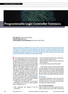
Figure 5 gives the traffic light program designed by one of the students. The program was compiled and downloaded to the PLC memory to run the traffic light automation. Figure 6 also gives a screen shot of the program after the start pushbutton was pressed and the PLC in run mode.
191
American Scientific Research Journal for Engineering, Technology, and Sciences (ASRJETS) (2016) Volume 15, No 1, pp 186-196
230 VAC
Wooden board
V AC +
V DC -
PSU
Terminal block
Input 0 Input 1 Input 2 Input 3 Input 4 Input 5 Input 6
Output 0 Output 1 Output 2 PLC Output 3 Output 4 RS 232
Input 7 Plastic box
Output 5 Plastic box
PC Programming device
Figure 4: Layout diagram of the proposed plc trainer
Figure 5: Traffic light automation control program designed by a student Students were able to develop their own PLC training platform and used it for the industrial control of processes with ease as marks obtained by students before and after test showed that there was an average performance improvement of students by 45.8%. Cost analysis also suggested that the training platform is relatively low cost ($ 214) and affordable. Size of the training platform had relatively reduced by careful space management during the mounting of components on the wooden board and the selected PLC used was small too.
192
American Scientific Research Journal for Engineering, Technology, and Sciences (ASRJETS) (2016) Volume 15, No 1, pp 186-196
Figure 6: Screen shot of the control program in online and run mode before the start pushbutton was pressed
Figure 7: Screen shot of the control program in online and run mode after the start (X0) pushbutton was pressed
193
American Scientific Research Journal for Engineering, Technology, and Sciences (ASRJETS) (2016) Volume 15, No 1, pp 186-196
Table 3: Device list of traffic light control program Device
Function
X0
Start pushbutton
X1
Stop pushbutton
M0
Internal relay
T0
10 s timer. Time base: 100 ms
T1
15 s timer. Time base: 100 ms
T2
4 s timer. Time base: 100 ms
Y0
Red lamp
Y1
Green lamp
Y2
Amber lamp
Cost analysis of building the PLC training platform is given in table 4. Table 4: Cost of items purchased for the training platform
Item
Description
Quantity
Unit
Rate
Cost US $
PLC
Delta DVP14SS211R PLC
1
Pieces
100
100
PSU
Delta DVPPS01/DVPPS02 power supply unit
1
Pieces
50
50
Delta DVPACAB2A30 programming cable
1
Pieces
25
25
5 Amps toggle switch
6
Pieces
1.5
9
Pushbutton
5 Amps pushbutton
2
Pieces
2
4
Pilot Lamp
24 VDC pilot lamp (2 red, 2 green, 2 yellow)
6
Pieces
2
12
Connectors for termination
2
Pieces
1
2
24 VDC contactor
2
Pieces
6
12
Programming Cable
Toggle Switch
Terminal Block Contactor TOTAL
214
5. Conclusion An interactive, less expensive and more portable PLC training platform for the industrial control of processes has been successfully developed. Students gained an average knowledge improvement of wiring and
194
American Scientific Research Journal for Engineering, Technology, and Sciences (ASRJETS) (2016) Volume 15, No 1, pp 186-196
programming the PLC on their own by 45.8% as shown by the pre-test and post-test results. Cost of developing the training platform was relatively low ($ 214) and the overall size of the training platform was relatively small as well. 6. Limitations and Future Research Directions Future works can consider obtaining more samples of input and output devices to be interfaced with the trainer. Supervisory Control and Data Acquisition (SCADA), Variable Frequency Drives (VFD) and Human Machine Interface (HMI) applications can be considered in future research as well. Acknowledgements We sincerely thank God Almighty, for all His strength, health, wisdom, blessings and above all love that He has shown us throughout this research paper. We very much acknowledge Mr. E. Normanyo of the Electrical and Electronic Engineering Department of the University of Mines and Technology for his great suggestions and support in making this research come to light. References [1] Kim, Y. S., Lee’ J. O. and Park C.W. “A hybrid learning system proposal for PLC Wiring Training Using AR”, e-Learning in Industrial Electronics (ICELIE), 2011 5th IEEE International Conference, pp. 90 – 94, 2011. [2] Lee, J. O. and Kim, Y. S “An AR-based Wiring Practice for PLC Training”, Journal of International Council on Electrical Engineering, Vol. 1, Issue 4, pp. 425 – 429, 2011. [3] Kim, Y. S. and Kim, H. ‘Design of a New Virtual Interaction Based PLC Training Using Virtual Sensors and Actuators: System and its Application’, International Journal of Distributed Sensor Networks, Vol. 2013, pp. 1 – 8, 2013. [4] Barrett, M. “The Design of a Portable Programmable Logic Controller (PLC) Training System for Use Outside of the Automation Laboratory”, International Symposium for Engineering Education, Dublin City University, Ireland, pp. 1 – 5, 2008. [5] Guo, L. and Pecen, R. “Design Projects in a Programmable Logic Controller PLC) Course in Electrical Engineering Technology”, American Society for Engineering Education, pp. 1 – 10, 2008. [6] Petruzella, F. D. Programmable Logic Controllers, McGraw-Hill New York, USA, 4th edition, 414 pp, 2011. [7] Chitra, S. and Raghavan, V. “Conveyor Control Using Programmable Logic Controller”, International Journal of Advancements in Research and Technology, Vol. 3, Issue 8, pp. 1 – 7, 2014.
195
American Scientific Research Journal for Engineering, Technology, and Sciences (ASRJETS) (2016) Volume 15, No 1, pp 186-196
[8] Bolton, W. Programmable Logic Controllers, Jordan Hill, Oxford, 5th Edition, 398 pp, 2009. [9]
Anon,
“Review
of
Available
Portable
PLC
Training”,
Available th
at
http://www.program-
plc.blogspot.com/2011/04/review-of-available-plc-training, Accessed on 26 August, 2015.
196