2012 IEEE/SICE International Symposium on System Integration (SII) Kyushu University, Fukuoka, Japan December 16-18, 2012
Development of a Segway Robot for an Intelligent Transport System Lerrel Joseph Pinto, Dong-Hyung Kim, Ji Yeong Lee, and Chang-Soo Han, Member, IEEE
Integration of the smaller Segway platforms like [ 1] with intelligence are also being pursued by robotic researchers. Obstacle avoidance [ 10], Human interaction and path planning [7, 1 1, 12] are interesting avenues of research being conducted on the Segway platforms. The result of this work is a stable and intuitively movable robotic platform, which provides a perfect base for imparting intelligence. Most of the challenges enlisted above have been substantially solved with the given hardware. Apart from the successful control of a Segway, the major advantage of this work is the transparency in operation and ease of implementation of intelligence in the Segway which is unavailable on the commercial model.
Abstract-The need for an intelligent transport system has been heightened in the present day, by the ever-growing demand to combine ease of transport with maximum efficacy. The Segway robot provides a platform which balances itself and transports the user in accordance to its natural lean. However in order
to
achieve
a
truly
intelligent
encapsulated in the form of
system,
challenges
stable control must
lirst
be
developed. This paper discusses the various aspects of Segway control and sheds light on solutions to solve difficulties in sensor data fusion, noise liltering and time lag in accumulation and transfer of data. Unaccounted time delays necessitate a control, different from an analytically derived control, so as to achieve a stable and easily movable Segway. A proposed control method has been implemented on a real human ridable Segway platform and
has
achieved
considerable
success
in
actual
experimentation.
II. I.
INTRODUCTION
ANALYTICAL MODEL OF SEGWAY
The presented model is an approximated model of the Segway system [8, 9]. The following assumptions have been adopted: • The angle between the human rider and the handle is constant • The center of mass of the Segway robot is at the center of the wheel's axis • The pitch angle is sufficiently small for their trigonometric functions to be approximated to a linear Taylor series expansion about O. • Actuator's inductance has a negligible effect on the response of the motor • There is no time delay in application of control and response time of the motor is negligibly small (However in a practical model these time delays play a important role)
HE Segway is a two wheeled self-balancing battery
Tpowered electric vehicle invented by Dean Kamen and
introduced in 200 1. A user can command the Segway to go forward by shifting his weight forward on the platform and backward by shifting his weight backward. The Segway developed by Segway Inc. uses gyroscopic sensors and fluid based leveling sensors to detect shift of weight. Computers and motors in the base of the Segway balance the device and maintain a speed corresponding to the user's command. The Segway PTs are driven by electric motors and can clock up to 20. 1km/h. The advantages of a Segway base platform are numerous; from zero turning radius and stability invariance on inclines to greater load carrying capacity and intuitive control, the Segway provides a motion greatly desirable for indoor personal transportation. However building a Segway supportive for further development of intelligence has its fair share of challenges. Control with noisy sensors, transmission time lags, motor dead zones and response time along with ensuring smooth human transportation has provided a fascinating challenge [2,3,5].
A.
Dynamic model
Manuscript received September 23, 2012. (Write the date on which you submitted your paper for review.) This research was supported by the MKE(The Ministry of Knowledge Economy), Korea, under the 'Advanced Robot Manipulation Research Center' support program supervised by the NIPA(National
IT
Industry
Promotion
Agency),
(grant
number
NIPA-20 12-HI502-12-1002).
L. 1. Pinto is with the Indian Institute of Technology Guwahati, Assam
India (e-mail:
[email protected]).
D. Kim, and 1. Lee are with the Department of Mechanical Engineering,
Hanyang
University
Seoul
campus,
Seoul,
Korea
(e-mail:
[email protected];
[email protected]). C. Han is with the Department of Mechanical Engineering, Hanyang University ERICA campus, Gyeonggi-do, Korea (phone: +82-31-400-5247; fax: +82-31-406-6398; e-mail:
[email protected]).
978-1-4673-1497 -8/12/$31.00 ©2012 IEEE
710
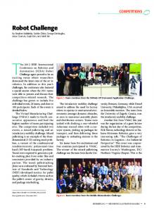
Fig. 1. Visualization of dynamjc model of human riding the segway robot.
With a given assumptions, we consider the dynamic model of segway with human shown in Fig. 1.
eb =kb 0) =knO) b
(7- 1)
eb =kn b xIr
(7-2)
m
For dynamic
equilibrium about the axis of rotation
(1)
Putting
(7-2) in (6) and rearranging, we get i =u a
For a dynamic equilibrium of the Segway in X-axis direction
F=(M +m)x Hence with (1) and
T
(2) As F
(2), we can derive the equation of motion
=
w
IR -knilRr b
v
=knu
a
(8)
a
2 I R -kkn x I Rr b
v
a
( 9)
a
2Tlr for the two wheeled Segway, we get
as v
(3)
()=(MgxCG sin () ) I 1 -(MFxCG cos () ) I (M +m)1
back-emf and
X=[()
e
denoting x
the
state
We
X
of
the
=
hence
get
a
modified
A'X + B'u' where
[ u" r
u' =
state
space
representation
voltage applied to the motor is
the controllable variable. The modified state representation
matrices A' and B' are obtained by manipulating equation
(3) in the state-space
vector
is the
generated by one wheel
is the Centre of gravity of
Full State Feedback Control of Segway System
By
OJrn
is the wheel angular velocity
OJw
ration. k and kb are the motor coefficients and T is the torque
the rider and F is the force exerted on the Segway system.
Let us rewrite the equation of motion
is the voltage applied to the motor.
which is derived from the radius of wheel r and gear reduction
rider, m is the mass of the Segway base. g has been taken as
form.
Uv
motor angular velocity and
is e the Pitch angular displacement which varies as the rider
XCG
a
through the motor, Ra is the motor resistance, eb is the motor
shifts his weight on the Segway. M is the mass of the human the acceleration due to gravity,
a
where La is the motor inductance, ia is the current flowing
where 1 is the Inertia of the segway system with the rider and
B.
(10)
F=2knu I Rr-2kkb n2xl R r2
x=FI(M+m)
(10) in the state space representation X
system as
[K K
applying u'=-kX with k=
x t ' the state-space equation which describe the
d
p
=
0
AX + Bn. Now by
K], ,
we obtain a
full state feedback control system with desired effect of state
given system is represented by
variable x=0 (This is done to allow the Segway to move
(4)
X=AX+Bu
around without trying to come back to its original position). Applying the Linear-quadratic (LQ) state feedback regulator
Where
for the above state space system by choosing 0
MgxCG / I
A=
0
0
0
0
0
0
0
0
0
0
0
0
'
B-
-MxCG /(M+m)I 0
Q=
l/(M+m)
0
and u=F. As it can be known from
1.11
0
0
0
0
1.11
0
0
0
0
0.01
0
0
0
0
10
[7.71] * 10-3
(4), the segway system requires
R=
the control input as the force acing on the base platform. However to relate with the motor input voltage, as the
The LQ regulator designs
controllable output is the voltage applied to the wheels, we integrate
the
above
stated
system
with
the
(11)
( 12)
k as a tradeoff between the
transient response and the control effort. The optimal control
motor
approach to this tradeoff is the definition of a performance
characteristic equations.
di a L+Ri+e =u a a a b dt
3 *10-
index J and the search of
k so as to minimize this index. The
solution found from the Riccati equation defines the solution. v
(5)
The
transient
response
constraints on X and
u
specifications
and
magnitude
are decided by the symmetric positive
semi definite matrix Q and the symmetric positive definite matrix R. Hence by choosing the above stated matrices, the response of the control system can be manipulated so as meet
(6)
the desired control specifications [6]. By solving the Riccati equation to get a positive semi 711
definite P
B.
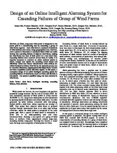
FPGA Control The moment the Segway is switched on, the controller and the various onboard sensors are powered, allowing the FPGA to spring into action immediately. Consider the control flow as given in Fig. 2. The FPGA accesses the raw sensor outputs (loops 1 & 2) and simultaneously processes it (loops 3 & 4) so as to obtain the state variables; in a parallel loop, the required control is computed (loop 5) based on the obtained state variables. Finally, the required control is applied to the motors (loop 6) when the control enable switch is turned on. In the flow chart outlined below, the square box processes represent the various parallel loops executed on the FPGA, the solid lines depict flow of control execution and the dashed lines represent one way transfer of data.
(13) And subsequently computing ( 1 4) We get k = [ -70.60
III.
35 67
-
.
0
-13.33]
( 15)
ALGORITHMS AND SEQUENCE OF CONTROL
A.
Overview The application of the analytically derived control fails during actual implementation due to the various delays involved in sensor data accumulation, computation and application. To counter such delays, the data accumulation and application of control on the actuators have been effectuated by a Field Programmable Gate Array (FPGA) on the National Instruments (NI) based c-RIO controller module. The FPGA functionally has direct access to the sensor input data and it first manipulates this data to generate a fairly accurate state of the robot in real time. It then computes the required control to the motors in a full state feedback control loop. Further, it applies the corresponding analog output to the motor driver. Exploiting the parallel processing capability of the FPGA, most of the required computational processes on the FPGA are implemented in parallel. However for a higher level of control and for the sake of data monitoring and experimentation, the Real Time (RT) controller of the c-RIO was exploited. Loop 1:
To get the state of the wheels: Loop 2 computes the encoder count (the number of encoder rotary units the actuator has moved) from the incremental rotary encoder output. Loop 4 then computes the linear velocity of the robot by taking the derivative of the encoder count variable in real time with a discrete time step of Ims along with multiplying it with a factor dependent on the encoder, gear reduction ratio and radius of the wheels. A high amplitude noise rejection filter is also implemented to obtain exploitable data. To get the anguwr state of the segway: Loop 1 access the analog outputs of the accelerometer and the two gyroscopes and converts the abstract analog data to linear acceleration, pitch angular displacement and pitch angular velocity by operating the data with predefined company specified constants. loop 1 also accesses the analog joystick data which is used for turning the robot. Loop 3 then performs the cardinal function of filtering the information obtained in loop 1. The acceleration is first converted to pitch angle using inverse trigonometric manipulation which is approximated to a linear function. It then applies sensor fusion using a complimentary filter in which a is the factor which determines the ratio of effect by the gyroscopic angle to the accelerometer angle to the complimentary angle.
Access the a na log
sensor outputs an d conve rt analog vo l tage into exploi tab le state varia b les
loop 3:
F ilter the sta te
a *( angle + gyro_ velocity * dt) I-a )*( accelerometecangle )
Complementary_angle
+
(
To apply control on the actuators: Loop 5 dynamically accesses the processed loop 3 and loop 4 outputs of the state variables, along with the input of full state feedback control parameters. It then generates an analog output corresponding to the control inputs to stabilize the system and turn according to joystick input.
.
.... --
loop 6:
=
Apply computed control if
switch to sta rt control
is turned on, else
Control for back and forward stabilizing: For the back and forth stabilizing motion, the input gain parameters are simply multiplied with the state variables and corresponding control is generated. However as a result of the motor dead zone, a threshold value is added to the control so as to
m a intain applied co ntTol to zero
Fig. 2. Control algorithm flow. Solid lines indicate control execution and Dashed lines indicate one way transfer of data
712
linearize the wheel velocity to voltage applied curve near the origin. Hence the control voltage is calculated as Control Voltage
*
=
Gain Factor variation with pitch angle 2.5 .,-----
* (Kp * filtered pitch angle + Kd Kv * linear velocity of robot) +
Gain Factor
filtered angular velocity +
1.5
dead zone threshold voltage
The Gain Factor is used to tune the control voltage during experimentation and plays an instrumental part in the RT based higher level control. Further, Kp, Kd and Kv are experimentally decided constants. By the analytical model we get the theoretical gains of Kp = -70.60, Kd = -35.67, Kv = - 13.33; However due to the hardware limitations and violations in the assumptions made in the dynamic modeling, the system was found to be unstable and hence required a fine tuning of the parameters so as to obtain a desirable smooth response.
0.5
=
yaw correction
yaw correction
Where Yp is the experimentally decided yaw corrective factor. The Joystick manipulative effect is decided by the following equation in a parallel loop =
T ra nsition zone (t l
Away from threshold of getback { tl
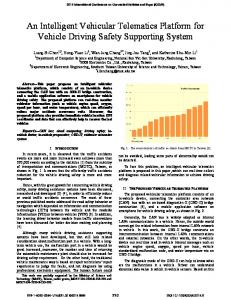
Higher level Segway control: The RT controller allows for a higher level control through the manipulation of the gain factors in the FPGA control loops. An example of such control, a simple variable gain factor control had been applied by implementing a smaller gain factor in the region close to the equilibrium point and a higher gain factor away from the stable region of control. Without this control, high frequency oscillations were observed at the zero pitch point possibly due to sudden acceleration in opposite directions and backlash in the motors. Application of this control helped counter this high frequency oscillation. In Fig. 3, the Gain Factor's variation with pitch angle implemented on the RT controller is shown. The maximum allowable gain factor here is 2 while the minimum gain factor allowable is 1.2.
back and forth control voltage -
IV.
EXPERIMENTAL RESULTS
By combining the RT controller's nonlinear control along with the FPGA, a stable and smooth Segway robot motion was observed. The following data charts (Fig. 4-7) are obtained during human driven movements on the Segway. A minimum gain factor of 1.2 and a maximum gain factor of 2 with the threshold of stability at 1° and the threshold of getback at 10° were used in this experiment. The gain values (III.B) used are Kp=22, Kct=3 and Kv=4. Turning was effectuated by using a Joystick and its response can be seen in Fig. 6.
Joystick manipulative effect +
(Joystick analog voltage - Joystick zero point voltage)
stability(tl
Ze ro Point
gain factor allowable is 1.2
* Yp
Joystick manipulative effect
within threshold of
stability(-)
controller. The maximum allowable gain factor here is 2 while the minimum
back and forth control voltage +
=
w ithin threshold of
Fig. 3. Gain Factor's variation with pitch angle implemented on the RT
* Yp
Right motor control voltage
T ransitio n lone (-)
getback ( -)
Right encoder count - Left encoder count +
=
�
-__"7' ____"---
�"'--------/ -
+-----
Away from threshold of
Joystick manipulative effect Left motor control voltage
-
�-
o +---�--�---�--�
Control for Yaw angle correction and turning: The method employed to prevent extemporaneous turning as a result of the actuator's directional preference along with effectuating intentional turning by joystick manipulation is described below Yaw correction
� +---
* Jp
This loop runs with a loop time of 1 ms, in which Jp is the Joystick control factor. C.
Real Time (RT) Controller The RT controller dually functions as a Data Monitor as well as a Higher Level Controller. The data monitoring capacity of the RT controller allows a visualization of sensor and actuator data through the medium of indicators and graphs.
Fig. 8 shows the Segway robot in experimentation with the above given gain values. A stable control was observed and it allowed comfortable transportation within an indoor environment.
713
15 10 5 o -5 -10 -15
-Control voltage (V)
-Filtered complimentary angle (deg)
-Fil effid complimenta ry angle (deg)
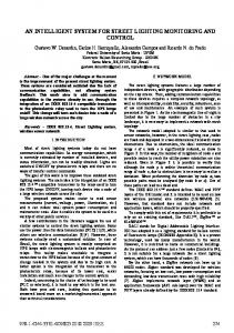
Fig. 4. This graph depicts the control voltage generated along with the pitch angle during forward and backward movement. The X time scale is in
-Average wheel velocity
seconds.
* 10
( m/ s)
Fig. 7. This graph shows the effect of rapid to and fro motions with the Segway. During high speeds, a rapid movement to the opposite direction helps in braking.
25 20 15 10
j
.lll,L
o :0
-5 -lO
I� rIA
11"[
'I �
l. �
[VI
iI!::.... -....
o
UUI I'
.j
A� � h. \ �Mn �olj �
W W� ;v f� "
Y
I"""'"
I�
r�
5
-15 -20 -25
-Filtered complimentary a ngle (deg )
- Filtered angular veloCity (deg/s) -Average wheel velocity * 1 0 (m/s)
Fig. 5. This graph shows the variation wheel velocity with the pitch angular data Fig. 8. This photograph shows the Segway robot in experimentation
f\,
-2 -3 -4
Ji\
r V\ •.AM' ''¥II " I\, 5 '\ 5� I 55\. Pl�\.. "'" "'Y \ V "
-1
V.
�
. ..
A
.41 \lit IJ!M.i r lJ r.: IA' � ;VV-'"
\
v
A. Safety Advancements in terrain recogmtIOn, obstacle avoidance algorithms, fall detection and rider health monitoring system in the already implemented controlled Segway robot would make the robot safer and hence more intelligent. These implementations would require Range scanners and bio sensors, for which the interface is readily available in the completed Segway robot.
-5 -6
CONCLUSION AND FUTURE PLAN OF ACTION
A stable drivable Segway robot is the result of this research work. In future work on this robot, one would expect developments in intelligence on the fronts of Safety and Path Planning.
r-
-Right wheel velocity *10 (mjs) -left wheel velocity *10 (mjs) -Joystick analog vol tage with 2.5V datum (V) Fig. 6. This graph shows the Right and left wheel velocities during the
application of turning control. It is interesting to note the difference in wheel velocities during the applied analog joystick control
B. Path Planning Since the major application of the Segway robot is in efficient indoor transportation. For this purpose a navigation tool in an indoor environment which provides directions to the destination from the start point would bring a radical change to the overall riding experience and also greatly reduce the time taken in manipulating environments previously unknown to the rider. Such advancement would require the implementation of an indoor SLAM and associated
714
algorithms, for which ample space has been provided on the developed Segway platform. VI. [1]
Hoa
G.
Nguyen
and
REFERENCES
John
Morrell, "Segway
Robotic Mobility
Platfonn", SPIE Proc. 5609: Mobile Robots XVII, October 27-28, 2004. [2]
Shui-Chun
Lin
and
Ching-Chih
Tsai,
"Development
of
a
Self-Balancing Human Transportation Vehicle for the Teaching of Feedback Control", IEEE Transactions on Education, vol. 52, no. 1, pp 157-168 Feb. 2009. [3]
Michael Baloh and Michael Parent, "Modeling and Model Verification of
an
Intelligent
Self-Balancing
Two-Wheeled
Vehicle
for
an
Autonomous Urban Transportation System", The Conference on Computational Intelligence, Robotics, and Autonomous Systems, Dec. 15 2003. [4]
SeongHee
Jeong
and
Takayuki
Takahashi,
"Wheeled
Inverted
Pendulum Type Assistant Robot: inverted Mobile, Standing, and Sitting Motions", International Conference on Intelligent Robots and Systems, Oct 29-Nov 2, 2007. [5]
S. W. Nawawi and M.N. Ahmad, "Development of a Two-Wheeled Inverted Pendulum Mobile Robot", The 5th Student Conference on
[6]
Kaustubh Pathak, JaumeFranch, and Sunil K. Agrawal, "Velocity and
Research and Development -SCOReD 2007. Position Control of a Wheeled Inverted Pendulum by Partial Feedback Linearization", IEEE TRANSACTIONS ON ROBOTICS, VOL. 21, NO. 3, JUNE 2005. [7]
Marcus Strand and Thomas Schamm, "Control of an autonomous personal transporter towards moving targets". 2009 IEEE Workshop on Advanced Robotics and its Social inpacts, November 23-25,2009.
[8] [9]
J. J Uicker (Jr). G. R Pennock, and J. E Shigley, Theory of Machines and Mechanisms, 3rd Ed., Oxford international Student Edition, 2009. K Ogata, Modern Control Engineering, 4th Ed., Pearson Education Asia, 2002.
[10] Cang Ye and Johann Borenstein, "Obstacle Avoidance for the Segway Robotic
Mobility
Platform",
international Conference on
American
Nuclear
Society
LOth
Robotics and Remote Systems for
Hazardous Environments, Gainesville, A, March 28-31, 2004.
[II] Marin Kobilarov and Gaurav S. Sukhatme, 'Time Optimal Path Planning on Outdoor Terrain for Mobile Robots under Dynamic Constraints" [12] Yunsu Ha and Shin'ichi Yuta, "Trajectory Tracking Control for Navigation of Self-contained Mobile Inverse Pendulum"
715