ABSTRACT: This paper presents a polishing expert system integrated with sensor information which can modify the polishing sequence and conditions initially ...
DEVELOPMENT OF A SENSOR INFORMATION INTEGRATED EXPERT SYSTEM FOR OPTIMIZING DIE POLISHING
J. H. Ahn1, Y.F. Shen1, H. Y. Kim1, H. D. Jeong1, K. K. Cho 2 Engineering Research Center for Net-Shape and Die Manufacturing 1 School of Mechanical Engineering, 2 Department of Industrial Engineering Pusan National University, Pusan, Korea 1,2
ABSTRACT: This paper presents a polishing expert system integrated with sensor information which can modify the polishing sequence and conditions initially set by the system using the on-site polishing status. A practical system using AE sensors is developed for the rotational polishing and the curved surface polishing. A database and knowledge base for polishing processes are established by using the results of experiments and also expert’s experience. Evaluations are performed for a die of headlight lamp by using both the sensor integrated expert system and the expert system without sensor. The results show that the sensor integrated expert system provides more optimal polishing conditions since the proposed system takes advantage of the on-line sensor information.
INTRODUCTION Die polishing technology is very critical to determine quality and performance of the final products and occupies up to 30~50% of the whole die manufacturing time.1 Die polishing processes have not been automated as much as other die machining processes because the automation requires a great deal of experience and skill of experts and its standardization is very hard. The most difficult problem for automation is how to determine of the optimal polishing sequence and conditions. 2 Several studies on the decision making for polishing sequence and conditions using an expert system in the polishing process have been reported. 3-5 In general, these studies built up a specific database composed of experimental data and working knowledge, and showed that a set of polishing conditions could be obtained from the database. However, the off-line decision inferred by the expert system is confined to a few limited situations due to lack of on-site information, and becomes inappropriate if some on-site conditions such as polishing direction, polishing pressure, and surface status, etc. are slightly changed. In reality, experts often change their decision on polishing sequence and conditions in order to adapt the confronting circumstances, although they have prepared a set of polishing sequence supposed to be optimal in the setup stage. That is one advantage of the human polishing compared with the mechanically automated polishing. In this study, Acoustic Emission (AE) sensor is used to substitute for human finger and a sensor information integrated expert system is developed to achieve die polishing in a globally optimal way. The polishing sequence and conditions obtained from the off-line expert system can be modified according to the current polishing status which is identified by the feedback signal from the AE sensor. And the performance of the proposed system is compared with the result obtained by the expert system without sensor information.
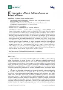
DIE POLISHING EXPERT SYSTEM Expertise of Polishing Process A skilled worker plans an optimal die polishing sequence based on his/her experience to get the required die surface condition from a pre-machined die that has lots of cusps and scratches on its surface. At first, a polishing tool of rather coarse mesh is selected and polishing is performed until the first tool is no longer effective to make the surface smoother. Then the next polishing tool of fine mesh is used and polishing is done again. Such processes are repeated until the target surface status is achieved. Figure 1 shows how to get a target surface roughness from an initial surface roughness by changing the polishing tools at some appropriate polishing intervals. The optimal interval for changing polishing tools depends on the operator’s judgement, which necessarily needs not only his/her experience and knowledge but also such sensory organisms as eye and finger. This is an important reason why it is difficult to fully automate the polishing process.
Ri Surface Roughness
Polishing Tool 1
Polishing Tool 2 Polishing Tool 3 Rt N1
N2
N3
Number of Polishing Passes
Figure 1.
Ri: Ri:Initial InitialValue Value Rt: Rt:Target TargetValue Value
Diminishment of surface roughness in polishing operation
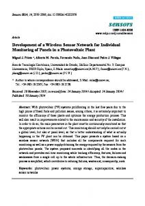
System Structure Figure 2 shows the structure of a proposed die polishing expert system integrated with AE sensor information. It consists of user interface, knowledge base for die polishing, inference engine, and AE monitoring.
Polishing K/B
INPUT
—Material —Initial Surface Status —Target Surface Status
OUTPUT
Polishing Inference Engine
Polishing Sequence & Conditions AE Sensor
AE Monitoring
Polishing Process �
Figure 2.
Structure of the AE sensor integrated polishing expert system
If both an initial value and a target value of the surface roughness are two inputs, a set of optimal polishing sequence including rotational speed, feedrate, pressure, tool mesh, and polishing time for the whole polishing process can be manufactured. While the polishing is performed according to the predetermined polishing sequence, AE
monitoring supervises whether each polishing tool works properly as expected. Depending on the on-site polishing status, the original sequence may be corrected.
Polishing Knowledge Base The knowledge base contains the polishing knowledge which is obtained through the related data handbooks, and experimental data as well as knowledge from the expert’s experience. Knowledge is usually represented in the form of rules. Knowledge acquisition. To obtain the optimal polishing sequence, a decision to set for tool mesh and polishing time is critical. The polishing time of each tool is related to the total amount of abrasive grains (TAG) contributing to polishing defined as equation (1).
TAG = N × S / F
(1)
where N is the number of polishing passes, F is feedrate, and S is spindle rotational speed. The relationship between surface roughness R and TAG for a combination of polishing tool and die material, as generally depicted in Figure 3, can be expressed approximately as equation (2).
R = (Rs − Re)exp(− × TAG) + Re
(2)
Surface Roughness (R)
where Re is the achievable surface roughness, Rs is a starting surface roughness, and is are the characteristic values for each coefficient of roughness diminishment. Re and combination of polishing tool and die material. The time when the surface roughness reaches a critical value Rc, which is the point of 90% of the difference in surface roughness, i.e. (Rs-Re), from Rs, is considered to be the best time for tool change. The TAG at that time is defined as the critical TAG, that is TAGc. Hence, given an initial surface roughness and a polishing tool, the desirable number of polishing passes can be determined by equations (1) and (2).
Rs
Rc Re
0
TAGc Total Amount of Abrasive Grains(TAG)
Figure 3. Surface roughness curve along with polishing time, in terms of TAG Through the polishing experiments under various polishing conditions, the characteristic values of each tool for the die material of SKD11 are obtained as shown in Figure 4. Knowledge representation. Knowledge is represented in the form of production rules as shown in Table 1. Figure 5 shows the structure of knowledge base for the proposed expert system. If an initial surface roughness exists between the lower limit Rmin and the upper limit Rmax, the critical TAG can be calculated using the characteristic values of the polishing tool, and the equations (1) and (2).
Re [µm]
1.0 0.6 0.2 CBN #100
CBN #200
CBN #400
CBN DiamondDiamondDiamond Diamond #100 #200 #400 #800 #600
(a) Achievable surface roughness (Re)
α
1.0 0.6 0.2 CBN #100
CBN #200
CBN #400
CBN Diamond DiamondDiamond Diamond #600 #100 #200 #400 #800
(b) Coefficeint of roughness diminishment (α )
Figure 4.
Characteristic values of polishing tools for the die material of SKD11
Table 1.
Rule Format in Knowledge Base
�
IF
l l
THEN
l
Polishing tool Grain size(Mesh #) Achievable surface roughness (Re) Coefficient (α)
Lower limit of premachined l surface roughness (Rmin) l Upper limit of premachined l surface roughness (Rmax) � �
Rule3 Rule2 Rule1
CBN
CBN
CBN #400
Rule12
Rule8
Rule4
CBN
Rule7 Rule6
#1000 Rule5
#200
Diamond
Diamond
Diamond
Diamond #200
#400
Rule11 Rule10
#1000 Rule9
Sheet
#100
#100
#100
Re
Re
Re
α
α
α
Sheet
Sheet
Sheet #1000
#400
#200
�
Figure 5.
Structure of knowledge base
Inference Engine The inference engine has two modules; one is for the off-line decision of the optimal polishing sequence and the other is for the on-line modification of the sequence assisted by AE sensor information. Off-line decision for the optimal polishing sequence. If a premachined surface roughness and a target surface roughness are the two inputs to the expert system, an optimal polishing sequence is drawn by the following inference procedure. [Step 1] Using rules in the knowledge base, all candidates available to polish the premachined surface are selected [Step 2] Among them, all but the only one candidate with the minimum polishing passes are
cancelled out. [Step 3] For the selected candidate, the THEN part of the production rule is executed to get an achievable surface roughness. [Step 4] It is checked that the achievable surface roughness is equal or better than the target surface roughness.
M1
Conflict solution
Conflict solution
Figure 6.
M8
M4
M3
M9
M6
M5
back track
M7
M2
M10
M12
M11
M13
Mi : i th Matching Ai : i th Action (T) : Tool found (F) : Tool Not found (G) : End of Search
Search tree for narrowing search space and finding the optimal solutions
�
Figure 6 shows the structure of the decision tree for searching the optimal polishing sequence. The depth first search among the forward chaining method is used as a searching algorithm. It starts from the initial status and continues until the desired status is found. For example, if no candidate is found or the target cannot be reached as in the node A3, it tracks back to A4. The same process is carrying out again. That is, if there is no node in a branch to pass all the steps, it moves to the next branch and continues until the target is reached. If the target is reached as in the node A10, all the nodes in the success branch become a set of possible polishing sequence. And after the rest of the trees are searched on the same way, a couple of possible sets are obtained. Finally, a set of polishing sequence with the minimum passes is chosen as the most optimal one. �
On-line modification for the polishing sequence. The number of polishing passes determined by the above off-line module is not absolute and it may be changeable depending on the on-site polishing conditions. The on-line modification is done based on the estimation of the on-site polishing status using AE signal. Figure 7 shows the procedure to modify the number of polishing passes. If the decrease rate of the current AE level to the previous one is below a preset threshold, the critical TAG is considered to be reached and then the tool is changed.
Acqusition of AE Level(i)
~
AE(i)=
AE Level(i)-AE Level(i-1) AE Level(i-1)
~
AE(i)
Threshold
100%
No
Yes Change polishing tool
Figure 7.
Procedure of on-line modification algorithm
EXPERIMENTS AND DISCUSSION Experimental Apparatus Polishing tool. Polishing experiment was performed on a vertical CNC machining center. A polishing tool head which is easily attached to the spindle of the machining center is specially developed. It is composed of universal joint, spring, ball spline shaft and arbor as shown in Figure 8. The universal joint makes the polishing tool contact always normally to the surface. The spring with the constant of 3.9N/mm is for holding and adjusting the polishing pressure. The ball spline shaft transmits the spindle torque to the polishing tool. The elastic polishing tool (EPT) was developed to enhance the curve adaptability and polishing efficiency. Figure 9 shows the structure and photograph of EPT. EPT consists of hard metal/resin bonded diamond pellets and a soft silicone body for elastically supporting the pellets.
Figure 8.
Structure of polishing tool head attached to machining center workpiece
frame Silicone body pellet
(a) Structure
(b) Photograph
��
Figure 9.
Structure of elastic polishing tool (EPT)
AE signal processing.� � Figure 10 shows the equipment for AE measurement. A charge amplifier built-in AE sensor (NANO 30) was mounted on the side face of a workpiece to suppress noises as much as possible. The detected AE signal is amplified by an amplifier and filtered through a high pass filter with cut-off frequency of 1kHz and then converted to the power in Root Mean Square (RMS) through a RMS converter. Finally, the RMS signal is digitized by an A/D converter for the AE monitoring in the expert system.
Figure 10.
Equipment for AE measurement
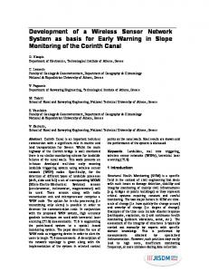
AE signal versus surface roughness. AE is known to be closely related to Material Removal Rate (MRR). MRR in polishing, which is relatively small compared with other machining processes, is highly dependent on the premachined surface status. As the surface is rougher, MRR gets larger and AE increases. Figure 11 shows the trend of the level of AE in power while a sample surface with a surface roughness of 7.65 Ra is being polished with polishing tools of mesh #100. Thus, it is concluded that the surface status and MRR can be indirectly estimated using the trend of AE level.
S urf ac e R oughness (Ra;µm )
10
P as s1
9
In itia l Surfac e
8 7 6
Pa ss2
5 4
Pa ss3 Pa ss4
3
Fina l Surfac e Pa ss8
2 1 0 .8
0 .7
0.6
0 .5
0 .4
A E Le vel(V)
Figure 11.
AE level and surface roughness during a sample polishing with tools of mesh #100
Experimental Results and Discussion Experiments using expert system without sensor. For evaluation tests, a die(mold) of a car headlight lamp shown in Figure 12 is used, whose material is SKD11. It has a spherical shape and is premachined by turning. The premachined surface status has a surface roughness of 8.26 Ra, while the target status is 0.025 Ra. Both status being input to the expert system without sensor information, a set of polishing sequence ( Ι ) listed in Table 2 is generated.
Figure 12.
Photograph of a die for car headlight lamp
Figure 13(a) shows variations of the AE level during the whole operation according to the sequence ( Ι ) and Figure 13(b) shows the surface roughness obtained after each polishing operation. In the first two polishing passes with a tool of mesh #100, the surface roughness gets rapidly well down to 1.0 Ra and then decreases gradually and very slowly along with the use of finer and finer mesh. Finally it reaches 0.023 Ra, a little smoother than the target roughness of 0.025 Ra. Experiment using the sensor integrated expert system. The same experiment was conducted by using the expert system integrated with sensor information that is developed in this study. All the initial conditions but the expert system itself are completely the same as the previous experiment. In this case, the change of a polishing tool now being used is determined by judging the on-site
polishing status at the end of each polishing sequence with the aid of the decrease rate of AE level.
Table 2.
Polishing Sequence and Conditions Resulted by Expert Systems #100
#200
#400
#1000
#4000
2
2
3
2
1
Pressure(kgf/cm )
6.09
3.80
3.43
3.02
2.88
Spindle speed(rpm)
600
800
800
900
1000
Number of passes
2
3
1
1
2
Pressure(kgf/cm )
6.09
3.80
3.43
3.02
2.88
Spindle speed(rpm)
600
800
800
900
1000
Number of passes Polishing Sequence ( )
2
Polishing Sequence ( )
2
A new polishing sequence (ΙΙ) obtained from this experiment is listed in Table 2, which is one pass shorter than the polishing sequence (Ι). The AE level and the surface roughness for this case are shown in Figure 14(a) and (b), respectively. Compared to the results in Figure 13, the total polishing time is reduced quite a little, while the final surface roughness obtained is 0.023 Ra, almost the same as the previous one. It is ascertained that polishing can be conducted in a more optimal way by using an on-line sensor signal implying the on-site polishing status.
8 7
0.14 # 10 0
0.12
NO .1
# 2 00
N O.2
N O.1
# 40 0 NO .2
NO .1
# 1 00 0
NO.2
NO .3
N O.1
# 40 0 0
NO.2
6
NO.1
0.10
5
R a( µm )
AE(V)
0.08 0.06 0.04
4 3 2
0.02
1
0.00 -0.02
0
-0.04
-1 0.0
0.4
0.8
1.2
1.6
2.0
2.4
2.8
3.2
3.6
4.0
0
1
2
3
P olishing T im e(Sec)
4
5
6
7
8
9
10
N o. o f Po lish in g S eq uence
���� �����
�
(a) AE level
(b) Surface roughness �
Figure 13.
Results of polishing by the expert system without sensor information
# 100 NO.1
0.14
# 200
NO.2
NO.1
NO.2
NO.3
# 400
# 1000
NO.1
NO.1
# 4000 NO.1
NO.2
8
0.12
7
0.10
6 0.08
Ra( µ m )
AErms(V)
5 0.06 0.04 0.02
4 3 2
0.00
1
-0.02
0
-0.04 0.0
0.4
0.8
1.2
1.6
2.0
2.4
Polishing Time(Sec)
(a) AE level Figure 14.
2.8
3.2
3.6
4.0
-1 0
1
2
3
4
5
6
7
No. of Polishing Sequenc e
(b) Surface roughness
Results of polishing by the sensor integrated expert system
8
9
10
CONCLUSION In this study, an expert system integrated with sensor information is proposed for the die polishing process and its performance is evaluated through the experiment a test die. The important results are summarized as follows. 1) The proposed polishing expert system is constructed so well that it makes a very reliable decision for the polishing sequence under the given initial and final surface status. 2) AE signal is useful to modify the polishing sequence and conditions in a more optimal way by monitoring the on-site polishing status. 3) From the practical view point, the sensor information integrated expert system makes up for drawbacks of the off-line decision drawn by the expert system without sensor information.
ACKNOWLEDGEMENTS This research was financially supported by the Korea Science and Engineering Foundation (KOSEF) through the Engineering Research Center for Net Shape and Die Manufacturing at Pusan National University. Also the authors would like to express sincere appreciation to C.H. Hwang, T.M. Lee and D.C. Lee for their assistance.
REFERENCES 1. Saito. K., Finishing and polishing of free-form surface, Bulletin of Japan Society of Precision Engineering, 18, 2, 104-109, 1984. 2, Kang. M. and Kim. S. G., CIM for mold factory automation, Annals of the CIRP, 39, 1, 1990. 3, Sasaki. T., Miyoshi .T., Saito. K., et al. Knowledge acquisition and automation of polishing operations for injection mold (1st report): Hand polishing properties of a skilled machinist, Journal of the Japan Society for Precision Engineering, 57, 3, 497-503, 1991.(in Japanese) 4. Sasaki. T., Miyoshi .T., Saito. K., et al. Knowledge acquisition and automation of polishing operations for injection mold (2nd report): Expert system for mold and die polishing operation, Journal of the Japan Society for Precision Engineering, 57, 12, 2151-2156, 1991. (in Japanese) 5. Sasaki. T., Miyoshi .T., Saito. K., et al. Knowledge acquisition and automation of polishing operations for injection mold (3rd Report): Development and construction of automatic polishing apparatus”, Journal of the Japan Society for Precision Engineering, 58, 12, 2037-2043, 1992. (in Japanese)