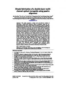
Development of a simple system for simultaneously measuring 6DOF geometric motion errors of a linear guide Feng Qibo,* Zhang Bin, Cui Cunxing, Kuang Cuifang, Zhai Yusheng, and You Fenglin Key Laboratory of Luminescence and Optical Information, Ministry of Education, Beijing Jiaotong University, Beijing 100044, China *
[email protected]
Abstract: A simple method for simultaneously measuring the 6DOF geometric motion errors of the linear guide was proposed. The mechanisms for measuring straightness and angular errors and for enhancing their resolution are described in detail. A common-path method for measuring the laser beam drift was proposed and it was used to compensate the errors produced by the laser beam drift in the 6DOF geometric error measurements. A compact 6DOF system was built. Calibration experiments with certain standard measurement meters showed that our system has a standard deviation of 0.5 µm in a range of ± 100 µm for the straightness measurements, and standard deviations of 0.5 " , 0.5 " , and 1.0 " in the range of ± 100 " for pitch, yaw, and roll measurements, respectively. ©2013 Optical Society of America OCIS codes: (120.0120) Instrumentation, measurement, and metrology; (120.3930) Metrological instrumentation.
References and links 1. 2. 3. 4. 5. 6. 7. 8. 9. 10. 11. 12. 13. 14.
A. C. Okafor and Y. M. Ertekin, “Vertical machining center accuracy characterization using laser interferometer, part one: linear positional errors,” J. Mater. Process. Technol. 105(3), 394–406 (2000). A. C. Okafor and Y. M. Ertekin, “Vertical machining center accuracy characterization using laser interferometer, part two: angular errors,” J. Mater. Process. Technol. 105(3), 407–420 (2000). J. Ni, P. S. Huang, and S. M. Wu, “A multi-degree-of-freedom measurement system for CMM geometric errors,” ASME J. Eng. Ind. 114, 362–389 (1992). P. S. Huang and J. Ni, “On-line error compensation of coordinate measuring machine,” Int. J. Mach. Tools Manuf. 35(5), 725–738 (1995). C. H. Liu, W. Y. Jywe, C. C. Hsu, and T. H. Hsu, “Development of a laser-based high-precision six-degrees-offreedom motion errors measuring system for linear stage,” Rev. Sci. Instrum. 76(5), 055110 (2005). C. Chou, L. Y. Chou, C. K. Peng, Y. C. Huang, and K. C. Fan, “CCD-based geometrical error measurement using Fourier phase shift algorithm,” Int. J. Mach. Tools Manuf. 37(5), 579–590 (1997). S. Shimizu, H. S. Lee, and N. Imai, “Simultaneous measuring method of table motion errors in 6 degrees of freedom,” Int. J. Japan Soc. Prec. Eng 28, 273–274 (1994). Q. Feng, B. Zhang, and C. Kuang, “Four degree-of-freedom geometric measurement system with common-path compensation for laser beam drift,” Int. J. Prec. Eng. Manufact. 9, 26–31 (2008). C. Kuang, Q. Feng, B. Zhang, B. Liu, S. Chen, and Z. Zhang, “A four-degree-of-freedom laser measurement system (FDMS) using a single-mode fiber-coupled laser module,” Sen. Actuators A 125(1), 100–108 (2005). K. C. Fan, M. J. Chen, and W. M. Huang, “A six-degree-of-freedom measurement system for the motion accuracy of linear stages,” Int. J. Mach. Tools Manuf. 38(3), 155–164 (1998). K. C. Fan and M. J. Chen, “6-Degree-of-freedom measurement system for the accuracy of X-Y stages,” Precis. Eng. 24(1), 15–23 (2000). W. Gao, Y. Arai, A. Shibuya, S. Kiyono, and C. H. Park, “Measurement of multi-degree-of-freedom error motions of a precision linear air-bearing stage,” Precis. Eng. 30(1), 96–103 (2006). C. H. Liu, H. L. Huang, and H. W. Lee, “Five-degrees-of-freedom diffractive laser encoder,” Appl. Opt. 48(14), 2767–2777 (2009). J. A. Kim, E. W. Bae, S. H. Kim, and Y. K. Kwak, “Design methods for six-degree-of-freedom displacement measurement systems using cooperative targets,” Precis. Eng. 26(1), 99–104 (2002).
#195143 - $15.00 USD Received 5 Aug 2013; revised 11 Oct 2013; accepted 13 Oct 2013; published 22 Oct 2013 (C) 2013 OSA 4 November 2013 | Vol. 21, No. 22 | DOI:10.1364/OE.21.025805 | OPTICS EXPRESS 25805
15. J. S. Kim, K. C. Kim, E. W. Bae, S. H. Kim, and Y. K. Kwak, “Six-degree-of-freedom displacement measurement system using a diffraction grating,” Rev. Sci. Instrum. 71(8), 3214–3219 (2000). 16. C. Y. Tsai, “Exact analytical approach for six-degree-of-freedom measurement using image-orientation-change method,” J. Opt. Soc. Am. A-Opt. Im. Sci. Vision. 29, 385–393 (2012). 17. U. Kenta, F. Ryosyu, O. Sonko, T. Toshiyuki, and K. Tomizo, “Geometric calibration of a coordinate measuring machine using a laser tracking system,” Meas. Sci. Technol. 16(12), 2466–2472 (2005). 18. C. B. Lee, G. H. Kim, and S. K. Lee, “Design and construction of a single unit multi-function optical encoder for a six-degree-of-freedom motion error measurement in an ultra-precision linear stage,” Meas. Sci. Technol. 22(10), 105901 (2011). 19. E. W. Bae, J. A. Kim, and S. H. Kim, “Multi-degree-of-freedom displacement measurement system for millistructures,” Meas. Sci. Technol. 12(9), 1495–1502 (2001). 20. D. P. Burt, P. S. Dobson, K. E. Docherty, C. W. Jones, R. K. Leach, S. Thoms, J. M. Weaver, and Y. Zhang, “Aperiodic interferometer for six degrees of freedom position measurement,” Opt. Lett. 37(7), 1247–1249 (2012). 21. S. W. Lee, R. Mayor, and J. Ni, “Development of a six-degree-of-freedom geometric error measurement system for a meso-scale machine tool,” J. Manuf. Sci. Eng. 127(4), 857–865 (2005). 22. P. Sandoz, “Nanometric position and displacement measurement of the six degrees of freedom by means of a patterned surface element,” Appl. Opt. 44(8), 1449–1453 (2005). 23. http://www.apisensor.com/. 24. Q. Feng, B. Zhang, and C. Kuang, “A straightness measurement system using a single-mode fiber-coupled laser module,” Opt. Laser Technol. 36(4), 279–283 (2004). 25. C. Kuang, E. Hong, Q. Feng, B. Zhang, and Z. Zhang, “A novel method to enhance the sensitivity for twodegrees-of-freedom straightness measurement,” Meas. Sci. Technol. 18(12), 3795–3800 (2007). 26. C. Kuang, E. Hong, and Q. Feng, “High-accuracy method for measuring two-dimensional angles of a linear guideway,” Opt. Eng. 46(5), 051016 (2007). 27. Y. Zhai, Q. Feng, and B. Zhang, “A simple roll measurement method based on a rectangular-prism,” Opt. Laser Technol. 44(4), 839–843 (2012). 28. Y. Zhai, Q. Feng, and B. Zhang, “A novel method for roll measurement based on grating,” Acta Opt. Sin. 28, 112–116 (2008). 29. C. Kuang, Q. Feng, B. Zhang, Z. Zhang, and S. Chen, “Measurement method of the roll angle,” Proc. SPIE 6150, 61502F (2006). 30. R. Cao, B. Zhang, and Q. Feng, “A method for roll-angle measurement in multi-degree-of-freedom measuring system,” Acta Opt. Sin. 28(12), 2344–2348 (2008). 31. F. You, B. Zhang, and Q. Feng, “A novel laser straightness measurement method with a beam bend compensation,” Optik (Stuttg.) 122(17), 1530–1534 (2011). 32. F. You, Q. Feng, and B. Zhang, “Straightness error measurement based on common-path compensation for laser beam drift,” Opt. Prec. Eng. 19(3), 515–519 (2011). 33. F. Zhu, J. Tan, and J. Cui, “Common-path design criteria for laser datum based measurement of small angle deviations and laser autocollimation methods in compliance with the criteria with high accuracy and stability,” Opt. Express 21, 188494 (2013). 34. K. Li, C. Kuang, and X. Liu, “Small angular displacement measurement based on an autocollimator and a common-path compensation principle,” Rev. Sci. Instrum. 84(1), 015108 (2013).
1. Introduction The linear guide is considered as the basis for linear motion in industrial applications and it is used as a key component in ultra-precision machining and measuring equipment such as CNC machines and coordinate measuring machines. The precision of the linear guide plays a key role in the machining and measuring precision of such equipment. As shown in Fig. 1, when a stage moves along the linear guide, there are six degrees of freedom (6DOF) along which geometric motion errors can occur; these include the position error ΔZ , straightness errors ΔX and ΔY along the x and y directions, and angular errors around the three axes corresponding to pitch θ X , yaw θY , and roll θ Z . For a typical threeaxis machine center, there are, in all, 21 geometric errors that are required to be measured step by step according to the relevant criteria [1, 2]. Current methods and techniques for measuring these errors employ laser interferometers such as the HP5529 and ML10. The laser interferometer is a single-geometric-error measurement device, which means that only one error component can be measured during each adjustment. Furthermore, different attachments and interferometer readjustments are needed for each error measurement process. In certain cases, it takes a few days or even a week to measure these 21 geometric errors, and the normal production process is also interrupted. As a result, measurement
#195143 - $15.00 USD Received 5 Aug 2013; revised 11 Oct 2013; accepted 13 Oct 2013; published 22 Oct 2013 (C) 2013 OSA 4 November 2013 | Vol. 21, No. 22 | DOI:10.1364/OE.21.025805 | OPTICS EXPRESS 25806
accuracy cannot be assured as the operators and the measuring environment change during every alignment of the measurement apparatus. Consequently, a primary need in this field is to develop a system that can simultaneously measure the 6DOF geometric motion errors in order to significantly decrease measurement time and to enhance measurement accuracy.
Fig. 1. Model of 6DOF geometric motion errors.
There are certain methods available for simultaneously measuring multi-degree-offreedom geometric errors of machine tools. An early work by Ni et al. is representative of this type of approach; their work focused on methods combining laser interference and laser collimation [3, 4]. These methods provided an accuracy of 1.0 µm for straightness error measurements and 0.5 arcs for angular error measurements, but the practical aspects involved complex optical configurations. Recently, based on the above mentioned measurement principle, Liu et al. used a commercial fiber-coupled laser interferometer and three parallel collimated laser beams to simultaneously measure 6DOF errors. The method provided an accuracy of 0.6 µm for straightness error measurements and 0.3 arcs for angular error measurements in the range of 120 mm [5], but it was only an experimental set-up and the moving head had a large size, which is not convenient for in situ measurements. Other researchers have also used similar combinational methods [6–9]; Fan et al. combined several sets of laser interferometers together to simultaneously measure six geometric errors despite having the disadvantages of a complex configuration and high cost [10–12]. The measurement method based on diffraction is another approach [13–15], but this method has relatively low measurement accuracy and limited measurement range. Tsai et al. proposed an analytical approach for measuring 6DOF geometric motion errors using the imageorientation-change method [16]. The configuration in this case is simple, but the computation is very complicated, and measurement accuracy depends on the accuracy of measuring the angle. The laser tracking method is another choice [17], and it provides the advantages of large measuring range and high measuring speed, but its measurement accuracy cannot satisfy the requirements of machine tool calibrations. Currently, there are certain new methods and apparatus to measure multi-degree-of-freedom geometric errors in micro-scale machine tools or stages that need a high precision [18–22]; however, these methods cannot be used for machine tool calibrations because of their limited measurement ranges. Thus far, despite the many multi-degree-of-freedom measurement methods and experimental equipments that are available, there is only one kind of commercially available 5/6D measuring system from Automated Precision Inc [23]; However, in this system, the roll error is measured by an electronic level, which cannot be used for vertical axis measurements. In this study, we propose a simple method for simultaneously measuring 6DOF geometric motion errors of the linear guide, and the methods for measuring straightness and angular errors are described in detail. A common-path method for measuring the laser beam drift is
#195143 - $15.00 USD Received 5 Aug 2013; revised 11 Oct 2013; accepted 13 Oct 2013; published 22 Oct 2013 (C) 2013 OSA 4 November 2013 | Vol. 21, No. 22 | DOI:10.1364/OE.21.025805 | OPTICS EXPRESS 25807
proposed and implemented to compensate the errors produced by the laser beam drift in the 6DOF geometric motion error measurements except the position error. We built a compact system that provides the advantages of a simple optical configuration, low cost, large measurement range, and high measurement accuracy. Further, we performed certain experiments to demonstrate our system’s feasibility and stability. 2. Methods for measuring single geometric error of linear guide 2.1. Straightness measurement The schematic for measuring the straightness error based on laser collimation is shown in Fig. 2 [24]. A corner cube retroreflector (RR) is used as the sensing element for measuring the straightness errors along the x and y directions. The collimated laser beam is taken as the datum line for the straightness measurements, and it is reflected back by the RR to a quadrant detector (QD1) located in the measurement head. When the target moves along the linear guide, the straightness error causes the spot position of the laser beam on QD1 to change, and this change can be easily measured as ΔX 1 2 ΔY1 . ΔY = 2 ΔX =
(1)
Here, ΔX 1 and ΔY1 denote the laser beam spot position changes in QD1 along the x- and yaxes, respectively. Y Z Laser
Fiber
X
RR
Collimator QD1
2ΔY ΔY
Fixed Unit
Moving Unit Moving Direction
Fig. 2. Schematic for measuring straightness errors.
From the measurement method shown in Fig. 2, it can be seen that the sensitivity for measuring straightness errors can be improved by a factor of 2 upon using a retroreflector. At the same time, there are no electric cable connections between the measurement head and the moving head, which is very convenient for in situ measurements. A single-mode fibercoupled laser diode or He–Ne laser can be used as the laser resource to improve the spatial stability of the laser beam. The use of multi-reflections and lens combinations can enhance the resolution for measuring straightness errors [25]. The resolution can be improved by a factor of 4 if the optical configuration shown in Fig. 3 is adopted, and it can be also deduced that the measurement resolution will improve by a factor of 2N when the laser beam is made to pass through the retroreflector N times; however, the air disturbance will correspondingly magnify the error due to the increased optical path. The resolution can be also improved by using the lens combination shown in Fig. 4, but the diameter of the measuring beam will be enlarged
#195143 - $15.00 USD Received 5 Aug 2013; revised 11 Oct 2013; accepted 13 Oct 2013; published 22 Oct 2013 (C) 2013 OSA 4 November 2013 | Vol. 21, No. 22 | DOI:10.1364/OE.21.025805 | OPTICS EXPRESS 25808
correspondingly, which will decrease the measuring resolution of the detector itself. A good balance between measurement resolution and precision is needed in practice. RR1 RR2
λ/4
2ΔΥ
Input PBS
Output
4ΔΥ
2ΔΥ
ΔΥ
Moving Unit
Fixed Unit
Moving Direction
Fig. 3. Multi-reflection method for improving straightness error measurement resolution. f1
f2
QD1
d1 Input d2 Output
Fixed Unit
Fig. 4. Lens combination method for improving straightness error measurement resolution.
A combined method by using both multi-reflections and the lens combination is shown in Fig. 5. Using this approach, certain comparative experiments were performed with a Renishaw ML10 laser interferometer, and it was determined that the maximum difference in measurement was less than 0.2 µm within the range of ± 100 µm and standard deviation was about 0.1 µm [25]. λ/4
Laser M
PBS RR2 Lens group PSD
Fixed Unit
RR1
Moving Unit Moving Direction
Fig. 5. Method combining multi-reflections and lens combination for improving straightness error measurement resolution.
2.2. Pitch and yaw measurement The schematic for measuring the pitch and yaw is illustrated in Fig. 6, which is in fact based on the autocollimation measurement method [26]. When the measuring unit moves along the linear guide, for any occurring pitch or yaw movement, the angle of the light reflected from the mirror M changes by an amount twice that of the pitch or the yaw. Now, the reflected light is focused on a position-sensitive detector (PSD1), and due to change in the angle, the spot position of the reflected light on the PSD1 also changes and this change can be easily determined. In this manner, the pitch or yaw can be obtained by measuring the position change on the PSD1 by using the following relations.
#195143 - $15.00 USD Received 5 Aug 2013; revised 11 Oct 2013; accepted 13 Oct 2013; published 22 Oct 2013 (C) 2013 OSA 4 November 2013 | Vol. 21, No. 22 | DOI:10.1364/OE.21.025805 | OPTICS EXPRESS 25809
ΔY2 2f ΔX 2 θY = . 2f
θX =
(2)
Here, f denotes the focal length of the lens L1 and ΔX 2 and ΔY2 denote the spot position change in the PSD1 along the x and y directions, respectively. 33.76
Fixed Unit
f
ΔY2
M1 PSD1
Moving Direction
θX
L1
Moving Unit Laser
Fiber Collimator
M
BS
Fig. 6. Schematic for measuring pitch and yaw.
In a manner similar to the approach used for enhancing straightness measurement resolution, the resolution for measuring the pitch and yaw can be enhanced by using the lens combination shown in Fig. 7. The lenses L1' and L'2 are arranged so as to suppress the angular drift of the measuring reference light, and further, the large size of the measuring beam is better for reducing the influence caused by air disturbance. The lens combination of L'3 and L'4 serves to improve the angular resolution while also reducing device dimensions. In theory, the total resolution can be improved by a factor of ( f combined f ) × ( f 2 f1 ) , where
f combiend denotes the combined focal length of the lenses L'3 and L'4 , and f denotes the focal
length of the lens L1 shown in Fig. 6, and f 2 and f1 denote the focal lengths of the lenses L'2 and L1' , respectively. Collimated Laser
L2′
L1′
PBS
M1
λ/4 L3′ M2
L4′
PSD
Moving Unit Moving Direction
Fixed Unit
Fig. 7. Lens combination method for improving angular error measurement resolution
Comparative experiments indicate that the standard deviation between our measuring method and that using the Renishaw ML10 laser interferometer is about 0.3 " in the measuring range of ± 60 " [26].
2.3. Roll measurement Obtaining roll measurement by optical methods is always a difficult problem; in particular, the integration of the roll measurement method with the other 5DOF geometric error measurements poses a very challenging problem. We have previously proposed several methods to address this issue [27–29], and here, we refer to a roll measurement method that uses a rhombic prism (BSP), as shown in Fig. 8 [30]. When the moving unit moves along the
#195143 - $15.00 USD Received 5 Aug 2013; revised 11 Oct 2013; accepted 13 Oct 2013; published 22 Oct 2013 (C) 2013 OSA 4 November 2013 | Vol. 21, No. 22 | DOI:10.1364/OE.21.025805 | OPTICS EXPRESS 25810
linear guide, for any occurring roll movement, the positions of the light spots on QD1 and QD2 along x direction change by ΔX 1 and ΔX 2 , respectively, and the error of the roll can be obtained by using the following relation.
θZ =
ΔX 2 − ΔX 1 . h
(3)
Here, h denotes the distance between the centers of the two output beams, and ΔX 2 and ΔX 1 denote the change in the spot position in QD2 and QD1, respectively, along the x direction.
Fig. 8. Schematic for measuring roll error using rhombic prism.
We obtained a resolution of 0.25 " and measurement accuracy of ± 1.0 " in the measurement range of ± 60 " by this method [30]. 3. Measurement and compensation of laser beam drift
The laser collimation measurement is a very simple method that can be used for straightness and angular error measurements. However, the accuracy of the laser collimation measurement can also be greatly limited by the laser beam drift. Typically, there are three kinds of factors that cause laser beam drifts; these include laser beam drift produced by the laser source itself, slow laser beam drift caused by the adjusting mechanism of the fixed laser device, and laser beam drift or bending caused by air disturbance or irregular air index distribution. The forms of the laser beam drift are the parallel drift, the angular drift, and drift due to bending of light. The laser beam drift introduced by the laser itself can be eliminated or greatly reduced by using single-mode fiber-coupled lasers, as shown in Fig. 2. However, it is difficult to reduce laser beam drift caused by changes in the refractive index of air. Some research work has been carried out to compensate for measurement errors produced by such a kind of laser beam drift, and the common-path compensation method appears to be most suitable [8, 31– 34]. However, in most cases, the compensation beam does not follow a common path with the measurement beam. Consequently, the two beams are not completely correlated, and the compensation results are not satisfactory. As mentioned above, the laser collimation method is adopted to measure straightness errors along two directions, the angular errors of the pitch, yaw, and roll. Therefore, it is very important to suppress laser beam drift as this can adversely affect the measurement results of all these multi-degree-of freedom geometric errors. A schematic of the common-path compensation method for measuring straightness errors is shown in Fig. 9. The collimation laser beam that is incident on the RR is reflected back to the lens L, and subsequently, it is focused onto the PSD2. If there is the angular drift of the laser beam along the plane XOZ, the laser spot position along the x-direction of PSD2 will vary by an amount ΔX PSD2 . Similarly, for angular drift along the plane YOZ, the position of
#195143 - $15.00 USD Received 5 Aug 2013; revised 11 Oct 2013; accepted 13 Oct 2013; published 22 Oct 2013 (C) 2013 OSA 4 November 2013 | Vol. 21, No. 22 | DOI:10.1364/OE.21.025805 | OPTICS EXPRESS 25811
the laser spot on PSD2 will change by ΔYPSD2 . As the angular drift of the laser beam is small, the angle of laser beam drift along the x and y directions can be obtained as ΔX PSD2 ΔX PSD2 Δα = tan −1 ≈ f2 f2 ΔYPSD2 ΔYPSD2 . Δβ = tan −1 ≈ f2 f2
(4)
Here, f 2 denotes the focal length of the lens L, and ΔYPSD2 and ΔX PSD2 denote the spot position changes along the y and x directions, respectively, on PSD2. Y
QD3 Laser
PSD2
Fixed Unit
RR
BS1 ΔY
Δβ
L
Δβ
ΔYPSD2
Z X
BS2
2Δ Y
f2
Moving Unit
QD1
ΔYQD1
Moving Direction
Fig. 9. Common-path measurement and compensation for laser beam drift.
Similarly, if the laser has a parallel laser beam drift of δ x or δ y along the x or y direction, the spot position of the laser beam that is reflected by a beam splitting mirror (BS1) and incident on QD3 changes by the same value along the x or y direction, as shown in Fig. 9, and the laser beam parallel drift can be easily obtained by measuring the change in spot position of the laser beam in QD3 using the following equation.
δ x = ΔX QD
3
δ y = ΔYQD .
(5)
3
Here, ΔX QD3 and ΔYQD3 denote the spot position changes along the x and y directions on QD3. As shown in Fig. 9, the laser beam reflected back from the RR is split into two beams by BS2. The beam reflected by the BS2, which is the measurement beam, reaches the QD1 and is used to detect straightness errors. The beam that is transmitted through BS2 reaches PSD2, and it is used to measure the beam angular drift, and this beam is hence designated as the compensation beam. Thus, we note that the measurement beam and the compensation beam follow a common path. Theoretically, the measurement errors produced due to laser beam drift can be reduced. In this light, Eq. (1) for obtaining the straightness errors can be modified as follows: ΔX = ΔY =
ΔX QD1 2 ΔYQD1 2
± l × Δα ± δ x
(6) ± l × Δβ ± δ y.
#195143 - $15.00 USD Received 5 Aug 2013; revised 11 Oct 2013; accepted 13 Oct 2013; published 22 Oct 2013 (C) 2013 OSA 4 November 2013 | Vol. 21, No. 22 | DOI:10.1364/OE.21.025805 | OPTICS EXPRESS 25812
Here, ΔX QD1 and ΔYQD1 denote the spot position changes obtained at QD1, Δα and Δβ denote the angular drift of the laser beam along the two directions, which can be obtained by Eq. (4), l denotes the moving distance that can be measured by the laser interferometer shown in Fig. 10, δ x and δ y denote the parallel drift of the laser beam that can be obtained by Eq. (5), and the sign ( ± ) is chosen according to the actual measurement. Similarly, Eq. (2) for calculating pitch and yaw can be modified as ΔY2 ± Δβ 2f (7) ΔX 2 θY = ± Δα . 2f Using the common-path measurement and compensation method shown in Fig. 9, the laser beam drift can be measured in real time by using Eqs. (4) and (5), and the measurement errors caused by the laser beam drift in the straightness, pitch, and yaw measurements can be calculated using Eqs. (6) and (7). We performed a set of experiments to demonstrate our method’s compensation effectiveness. For the straightness error measurements, when the distance between the moving target and the laser head was 8 m , the maximum fluctuation decreased from about 25 µm before compensation to about 12 µm after compensation in a period of 16 minutes. For the pitch and yaw measurements, when the distance between the target and the laser head was 10 m , the maximum fluctuation decreased from about 12 arcs before compensation to about 3 arcs after compensation in a period of 40 minutes. In fact, theoretical analysis shows that the influence of the laser beam drift produced by the laser source and its mechanism on the straightness and angular error measurements can be compensated completely, but the bending of light can be compensated for only partially [31].
θX =
4. Simultaneous measurements of 6DOF geometric motion errors
4.1. Method and system for simultaneously measuring 6DOF geometric motion errors The block diagram of the system that can be used for simultaneously measuring the 6DOF geometric motion errors is shown in Fig. 10. The principles of laser collimation and autocollimation were used to measure the all straightness and angular errors, and laser interferometry was used to measure the position error. The common-path compensation method was adopted to reduce the influence of laser beam drift on the accuracy of the straightness and angular error measurements. Position error: As shown in Fig. 10, the laser beam is collimated by a collimator and reflected by BS1 and RR1, and subsequently, the beam is incident on the detector D. This beam is used as the reference signal for the interference, while the laser beam, which passes through BS1 and BS2 and subsequently is reflected by RR2 and BS1 finally reaching the detector D, is used as the interference signal. These two beams undergo interference, and the resulting position error can be measured by D. Straightness error and roll: Using the measurement methods shown Fig. 2 and using Eq. (6), the straightness errors along the x and y directions can be measured. As shown in the figure, the laser beam passes through BS1, BS2, BS, and is reflected by RR2. Subsequently, it passes through BSP and is reflected by both BS3 and BS4, until it finally reaches QD1. Similarly, the straightness errors along two directions can be also measured by the laser beam that finally reaches QD2. Using the method shown in Fig. 8 and from Eq. (3), the roll error can be obtained by measuring the spot position changes along the x direction in QD1 and QD2.
#195143 - $15.00 USD Received 5 Aug 2013; revised 11 Oct 2013; accepted 13 Oct 2013; published 22 Oct 2013 (C) 2013 OSA 4 November 2013 | Vol. 21, No. 22 | DOI:10.1364/OE.21.025805 | OPTICS EXPRESS 25813
Pitch and yaw: Using the method shown in Fig. 6 and from Eq. (7), the yaw and pitch can be measured by the laser beam that is reflected by BS and BS2 while finally reaching PSD1. L1 M1
PSD1
BSP
Collimator
RR1
QD2 BS2
BS Coating
RR2
Laser BS3 BS1
QD1 BS4
D
L2 PSD2
Fixed Unit
Moving Unit Moving Direction
Fig. 10. Schematic for simultaneously measuring 6DOF geometric motion errors.
Common-path compensation for laser beam drift: As shown in Figs. 9 and 10, the lens L2 and PSD2 are used to measure the angular beam drift, and the errors produced by the laser beam angular drift in the straightness and angular error measurements can be compensated based on the method mentioned in Section 3. The roll error is obtained by measuring two sets of straightness errors from QD1 and QD2, and its error caused by the laser beam drift is automatically compensated after the straightness error is compensated using Eq. (6).
4.2. Experimental results and analysis Figure 11 shows the prototype developed in the study. Subsequently, we performed certain experiments to evaluate the effectiveness of the system. Our system
Target
Our system
API target Moving unit Linear guide Step motor
API
Fig. 11. Calibration experiments of developed system with API system.
Calibration experiments: The calibrations regarding the straightness error were performed with the LG-50 grating displacement sensor as the standard meter with its resolution of 0.05 µm and accuracy of 0.1 µm . The experimental results for calibration are shown in Figs. 12(a) and 12(b). The developed system has a resolution of 0.2 µm , and a standard deviation along both the x- and y- axes is less than 0.5 µm within a measurement range of ± 100 µm . The calibrations of pitch and yaw were performed with the autocollimator model Collapex EXP as a standard meter with its angle resolution of 0.01 " and accuracy of 0.2 " .
#195143 - $15.00 USD Received 5 Aug 2013; revised 11 Oct 2013; accepted 13 Oct 2013; published 22 Oct 2013 (C) 2013 OSA 4 November 2013 | Vol. 21, No. 22 | DOI:10.1364/OE.21.025805 | OPTICS EXPRESS 25814
The experimental results for the calibration process are shown in Figs. 12(c) and 12(d). The developed system has a resolution of 0.25 " . The point-to-point deviation of the pitch and yaw was found to vary from −1.3 " to 0.5 " and from −1.0 " to 0.8 " , respectively, within the measurement range of ±100" , and the standard deviation for measuring the pitch and yaw was about 0.5 " .
Fig. 12. Calibration results of 6DOF geometric motion errors. (a) Straightness errors along xaxis. (b) Straightness errors along y-axis. (c) Pitch. (d) Yaw. (e) Roll. (f) Length.
The roll was calibrated by using the model WL11 electronic level whose resolution was 0.2 " and measurement range was 1000 " . Figure 12(e) shows the experimental results. The developed system has a resolution of 0.25 " . The point-to-point deviation of the roll measurements was found to range from −2.0 " to 1.8 " with a standard deviation of about 1.0 " within a range of ±100" .
#195143 - $15.00 USD Received 5 Aug 2013; revised 11 Oct 2013; accepted 13 Oct 2013; published 22 Oct 2013 (C) 2013 OSA 4 November 2013 | Vol. 21, No. 22 | DOI:10.1364/OE.21.025805 | OPTICS EXPRESS 25815
The position error was calibrated with the API 5D measurement system, and the corresponding experimental results are shown in Fig. 12(f). The maximum deviation is less than 0.8 µm within the measurement range of 500 mm . As shown in Fig. 11, our system and the API system were placed at opposite ends of the linear guide that was about 700 mm long. The difference in the measurement of length between the two systems is duo to the temperature change and non-uniform distribution of the temperature in the laboratory. As can be observed from Fig. 12, there is some difference between the measurements obtained using our system and those obtained using the standard meters, and this is because of certain systemic errors existing in our system. For example, as shown in Fig. 10, the two beams used to measure the roll that reach QD1 and QD2 should be ideally parallel to each other; however, these two beams cannot be perfectly parallel because of manufacturing deviations in the optical elements such as RR1 and BSP. These deviations are bound to produce certain systemic errors in the roll measurement. Theoretically, these errors can be eliminated or be reduced greatly by error modeling, which forms our future work.
#195143 - $15.00 USD Received 5 Aug 2013; revised 11 Oct 2013; accepted 13 Oct 2013; published 22 Oct 2013 (C) 2013 OSA 4 November 2013 | Vol. 21, No. 22 | DOI:10.1364/OE.21.025805 | OPTICS EXPRESS 25816
60
1st 2nd 3rd Residuals
40
1.3 0.8
20
0.3
0
-0.2
-20
-0.7
-40 0
100
200
300
400
500
600
-1.2 700
0
1.6 1st 2nd 3rd Residuals
-20
1
-40
0.4
-60
-0.2
-80 0
100
Position/mm
200
300
400
500
600
-0.8 700
Position/mm (b)
(a)
2
140
0.4
1.4
105
0.1
-80
0.8
70
-0.2
-120
0.2
35
0
1st 2nd 3rd Residuals
-40
-160 0
100
200
300
400
-0.4 500
1st 2nd 3rd Residuals
0 0
100
300
400
-0.8 500
Position/mm (d)
Position/mm (c) 160
1.4 1st 2nd 3rd Residuals
120
200
-0.5
0.4
0.8
500 1st 2nd 3rd Residuals
400
0.5
300
0.2
200
-0.1
100
-0.4
-0.6
80
40
-1.6
0 0
100
200
300
400
-2.6 500
0 0
100
200
300
Position/mm
API Position/mm
(e)
(f)
400
-0.7 500
Fig. 13. Measurement repeatability trials for developed system. (a) Straightness errors along x-axis. (b) Straightness errors along y-axis. (c) Pitch. (d) Yaw. (e) Roll. (f) Position errors.
Repeatability experiments: To test the stability of the developed system, we obtained three measurements along a 700 mm linear guide placed on the optical platform. The step was 50 mm and the total move distance was 500 mm . The measurement results for this experimental trial are shown in Figs. 13(a)-13(f). It can be seen that our system exhibits consistent repeatability of the results. The maximum deviation for the straightness errors along the x and y directions is about ± 1.2 µm , and the maximum deviations of the pitch, yaw and roll measurements are about ± 1.0 " , ± 0.8 " , and ± 1.8 " , respectively, while the maximum deviation of the position error is about ± 0.6 µm . The primary reason causing these deviations is the small joint clearance between the linear guide and the stage. At the same time, the linear guide is not firmly fixed to the optical platform (see Fig. 11), which also produces some errors in the measurement system.
#195143 - $15.00 USD Received 5 Aug 2013; revised 11 Oct 2013; accepted 13 Oct 2013; published 22 Oct 2013 (C) 2013 OSA 4 November 2013 | Vol. 21, No. 22 | DOI:10.1364/OE.21.025805 | OPTICS EXPRESS 25817
4.3. Main factors causing measurement errors in developed system There are mainly three error sources that influence the measurement accuracy of the developed system. The first kind of error is due to laser beam drift, which produces random errors in the measurement system; this kind of error can be reduced by use of the commonpath compensation method mentioned in Section 3. The second type of error arises due to inevitable manufacturing and installation deviations between the designed and practically realized optical elements. For example, the three angles among the three reflected mirrors in the retroreflector are not exactly 90 degrees; there is an angle deviation, and this deviation is bound to produce certain systemic errors in the measurement system. At the same time, there are also some deviations that occur during optical element installation, and this kind of deviation also causes certain systemic errors in the measurements. The third kind of error is due to some crosstalk errors that occur between all these 6DOF geometric motion errors; i.e., the straightness error influences on the angular errors and vice versa. In theory, these measurement errors caused by the optical element manufacturing deviations, installation deviations, and crosstalk errors are systemic. These errors can be compensated through a careful analysis and establishing a mathematic model, and this aspect will form our future research work. 4.4. Improving resolution of developed system Lens3 M1
PSD1 LP3 QD2
Lens2 M2
RR2
RR1
M3
Laser
D
Special Prism
BS2
RR3
BS Coating
BS1
LP 2 PBS 1
PBS 2
λ/4
QD1
Moving Unit BS4 Polarzing film(PL 1)
Moving Direction Lens1
Lens4 PSD2
Fixed Unit
Fig. 14. Schematic towards improving measurement resolution of 6DOF system.
The resolution of our system for measuring the 6DOF geometric motion errors can be enhanced by using the methods mentioned in Section 2. The schematic towards improving the resolution of our 6DOF geometric motion error measurement system is shown in Fig. 14. The combinational lens3 is used to amplify the resolution of the pitch and yaw measurements, and the combination lens1 and lens2 is used to enhance the measurement resolution of the two straightness errors obtained from QD1 and QD2. Consequently, the roll measurement resolution can also be enhanced. By using the two polarizing prisms (PBS1, PBS2) and the two corner retroreflectors (RR1, RR2), the position error measurement can be doubled. 5. Conclusion
Our proposed method and developed instrument for simultaneously measuring 6DOF geometric errors can contribute significantly to the research, development and manufacturing of high-precision equipment. Our proposed method provides several advantages such as
#195143 - $15.00 USD Received 5 Aug 2013; revised 11 Oct 2013; accepted 13 Oct 2013; published 22 Oct 2013 (C) 2013 OSA 4 November 2013 | Vol. 21, No. 22 | DOI:10.1364/OE.21.025805 | OPTICS EXPRESS 25818
device compactness, low cost, and the lack of cable connections in the moving head. The feasibility and reliability of our system are demonstrated via certain experiments. The measuring accuracy of the system can be improved further through error modeling and compensation. Acknowledgments
The authors acknowledge financial support from the Chinese National Natural Science Foundation under Grant Nos.51027006 and 50675017.
#195143 - $15.00 USD Received 5 Aug 2013; revised 11 Oct 2013; accepted 13 Oct 2013; published 22 Oct 2013 (C) 2013 OSA 4 November 2013 | Vol. 21, No. 22 | DOI:10.1364/OE.21.025805 | OPTICS EXPRESS 25819