9th HSTAM International Congress on Mechanics Limassol, Cyprus, 12 – 14 July, 2010
DEVELOPMENT OF A SIMPLIFIED MECHANICAL MODEL TO ESTIMATE THE SEISMIC VULNERABILITY OF CULTURAL HERITAGE MASONRY BUILDINGS Dimitrios Vamvatsikos1, and Stavroula J. Pantazopoulou2 1
Department of Civil and Environmental Engineering University of Cyprus P.O. Box 20537, 1678 Nicosia, Cyprus e-mail:
[email protected] 2
Department of Civil Engineering Demokritus University of Thrace 67100 Xanthi, Greece e-mail:
[email protected]
Keywords: Earthquake, masonry, simplified model, fragility, static pushover. Abstract. A simplified mechanical model is developed for heritage masonry buildings to address the problem of the collective seismic vulnerability of historical cities. Our focus is the derivation of capacity curves based on parameterized first-mode structural models that are flexible enough to represent an ensemble of similar buildings. The structural model estimates lateral strength using a Mohr-Coulomb type failure criterion of the load-bearing walls deforming in-plane in shear in combination with a yield-line mechanism for the out-of-plane flexural deformation of the orthogonal walls. The resulting equivalent models are simple enough to allow an analytic first-mode representation of their seismic behavior that is suitable for evaluation via static pushover in a manner that is consistent with current performance-based seismic assessment frameworks. 1
INTRODUCTION
The vulnerability of historical city cores is an important issue for numerous cities in seismic areas, a fact exemplified by the recent devastation of the city of L’ Aquilla by the 2009 Abruzzo earthquake. Historical cores are typically composed of numerous buildings of stone masonry often built over different periods, with varying degrees of workmanship and usually in various degrees of disrepair. It is not surprising that quantifying their collective seismic vulnerability is not a simple problem. Actually, this has been a recurring issue of interest in the literature, where multiple research teams have made valuable contributions, especially in the context of modeling, some aiming towards more accurate and elaborate models and others towards simpler and more tractable ones. For example, Tanrikulu et al[1] have presented models of masonry structures under seismic excitation, while D’Ayala et al[2] use simple mechanical models for a case-study of seismic loss estimation for the city of Lisbon. More recently, D’Ayala and Speranza[3] have offered a comprehensive analysis of collapse mechanisms of masonry structures, meant to capture such effects with few equations. Working in accordance with recent advances in performance-based earthquake engineering frameworks (e.g. Cornell and Krawinkler[4]), such simple models may be used to extract useful information about the vulnerability of masonry buildings. This was accomplished, for example, by Vamvatsikos and Pantazopoulou[5] who offered such a simplified methodoly, geared towards application to groups of similar structures existing in historical center of many old cities. Herein, we aim to provide the details of a suitable mechanical model to form the basis of such a vulnerability estimation method, mainly focusing its application on the timber-laced masonry (TLM) buildings of the city of Xanthi in Northern Greece. 2 MECHANICAL MODEL In TLM, lateral load resistance is imparted by interface friction between mortar and stone or brick, and enhanced by the bearing action of gravity loads. Timber lacing (referred to hereon as tiers) acts in masonry walls as shear reinforcement, interrupting the planes of diagonal tension failure exactly in the same manner as horizontal reinforcing bars function as shear reinforcement in conventional RC walls (Tastani et al[6]). Tiers are 0.1m thick timber beams embedded in the masonry parallel to the joints. A basic characteristic of this type of construction is the relatively large area ratio of exterior and interior walls, either reinforced or unreinforced with tiers, and the relatively flexible diaphragms. This characteristic imparts a great degree of robustness in the
Dimitrios Vamvatsikos, and Stavroula J. Pantazopoulou. structure. Some walls have an aspect ratio (height to length) of almost 1.0 (with the exception of piers forming between upper-storey windows) and therefore the behavior of the walls in their plane is dominated by shear deformation, whereas others are significantly longer with aspect ratios of about 0.5 and flexural out-of-plane deformation governing their response. TLM buildings of Xanthi, being entirely utilitarian, were built in the same chronological period with local methods and workmen and using locally produced materials from the quarry of the Kosynthos river. Thus, such residential houses present several typifying characteristics that fall within well defined ranges of values. The typical house (Fig.1) is a two storey dwelling with storey height ranging from 2.6 to 3 m. The floor plan is nearly rectangular (sides ranging from 8 to 12 m), with floor area ranging between 60 and 130 m2. The lower floor and the basement, if it exists, are constructed with perimeter stone masonry walls; wall thickness ranges from 550mm to 700mm.
Figure 1. (a) Typical example of timber laced stone-masonry dwelling in Xanthi. (b) Layout of TLM (from Vintzileou[7]). Figure 2 plots the average shear stress-strain diagram for stone masonry walls without tiers adopted by Eurocode 8-III[8]. Shear strength, fv, is estimated as a weighted product of compressive strength of building block strength fbc and joint mortar compressive strength, fmc: fv=1.25kfbc0.7fmc0.3 (stress terms in MPa, k in the range of 0.35 to 0.55). The range of values of the parameters listed above may vary, but the mean strength is estimated as 0.5MPa with a standard deviation of 0.15MPa. Note that the code recommended values for the shear distortion upon yielding of the masonry wall (yielding here is used to identify the onset of friction-sliding behavior along mortar joints after the occurrence of diagonal cracking) is in the range of 0.15%, whereas the shear strain ductility ranges, reaching values as high as 3 in cases of timber laced masonry (EC8-III[8]). The design code model for shear strength rides on a Mohr-Coulomb type of idealization of the behavior of stone masonry, according with which, the cracking shear strength, vRd1, of unreinforced masonry is expressed in terms of the inherent stone-binder cohesion, σz is the normal compressive stress clamping the potential sliding plane, and µ is the apparent frictional coefficient. fv
0.0015
0.007
γ
Figure 2. Code-recommended resistance curve for masonry walls.
v Rd1 = c + µ ⋅ σ z .
(1)
In obtaining the code relationship the frictional component of shear strength has been neglected on the assumption that normal stresses owing to overbearing loads are very small; this simplifies Eq. (1) to a Trescatype failure criterion. The cohesion c may alternatively be taken as the weighted product of tensile (ft’) and compressive (fc’) strengths of the weaker component of the composite masonry (i.e., of the mortar): c=0.5(ft’
Dimitrios Vamvatsikos, and Stavroula J. Pantazopoulou. fc’)0.5 (where ft’ is approximated as 0.1fc’); this approach yields commensurate results with those given earlier (conservatively around 0.5MPa). The contribution of tiers in this strength model is estimated by the total force, Vb, sustained by those tier elements that intersect a 45o plane of failure after diagonal cracking. Another criterion for failure of the structure is the magnitude of curvature that may be sustained prior to failure, by walls oriented orthogonal to the seismic action and engaged in out of plane bending. For walls without tiers this is equal to the cracking strain of masonry, divided by the distance to the neutral axis, i.e., φcr=2(0.1fc’/Ewt), or approximately 0.0001/t . In the presence of tiers, the walls possess flexural ductility. Then, exceeding φcr may still result in cracking, however, actual failure is associated with the ultimate curvature taking approximately the value of φu = 0.0035/0.3t (the crushing strain of masonry taken equal to 0.0035).
Seismic loading y t
V q(z) Vooo
n1 n2
n5 n4
n3
Cantilever model of building ∆s ∆sh ∆tot
Ν
b
Η x
z x
a
x Apply field of gravity in direction of interest = γwt Figure 3. (a) Typical plan of traditional masonry structure, (b) seismic loading, and (c) method used to approximate fundamental lateral translational mode of vibration. 3
VIBRATION MODE SHAPE
Due to their low aspect ratio, robustness of load bearing structure and mode of construction (layered joints and building blocks), masonry walls develop insignificant flexural action in the plane of seismic loading, their fundamental mode of vibration corresponding to a shear-cantilever-type behavior, marked by a decreasing shear angle of distortion with height. This result is supported by 3-D finite element simulations of the outer shell of these structures; extreme diaphragm flexibility promotes the tendency of walls normal to the plane of action to also bend in the out of plane direction increasing the risk of a weak mode of failure with detachment of orthogonal walls at the corners. Considering the true complexity of the mechanical problem, the uncertainty with regards to the mechanical behavior of the materials, the extent of damage, and the actual state of interaction that occurs at the interfaces of different materials (e.g., timber and mortar or stones, soil with masonry, etc.) any calculation-intensive approach would be incompatible with the actual level of confidence in the input values. For this reason, response is considered in the fundamental mode of vibration only. To obtain the best approximation to the fundamental lateral shape of the building, the cantilever elastic model of the structure is solved under its gravity loads acting in the direction of expected seismic excitation (here, along the x dimension of the structure, Fig. 3) (Clough and Penzien[9]), i.e., γw·t, where γw the specific gravity of the stone walls and t the thickness; the resulting lateral deflection comprises two components, ∆s(z) and ∆f(y,z), where the first represents the corner displacement along the x direction of the walls parallel to the seismic action, which is owing to shear distortion of these walls, whereas the second represents the additional deflection of the walls orthogonal to the motion, owing to out-of-plane flexural curvature. If we neglect the two forces at roof and story, the shear force at a height z in a single wall is V(z)=γw·t·(a+0.5b)·(H-z), where we have assumed that half of the out-of-plane wall load is supported directly by the in-plane walls. The corresponding shear strain is γs=V(z)/GwA w=γw·(a+0.5b)(H-z)/aGw, and the corresponding displacement at the top of the structure ΦS(H)=0.5·γw(a+0.5b)H2/aGw; similarly, for the walls orthogonal to the load (considered here as plates having two sides pinned, the bottom fixed and the top side free), the out-of-plane deflection at midcrest is
Ewt 3 H γ ta 4 b ∆ f , H = 0.125 − 0.115 w , where D = . b D 12(1 − ν 2 ) 2
(2)
for usual ratios of H/b ranging from 0.1 to 1.0, shear modulus Gw=0.4Ew and Poisson ratio v = 0.30[10]. This should be multiplied by a factor of about 2/(2+1.1415) = 0.6 to approximate the partial clamping of the “pinned” edges. Corner displacements in the fundamental shape of vibration vary along the height as a second order function of z (i.e., due to the linearly varying expression for shear strain derived above); thus:
Dimitrios Vamvatsikos, and Stavroula J. Pantazopoulou.
2 zH − z 2 Φ S ( z ) = Φ S ( H ) 2 H
(3)
Figure 4. Mode shape of out-of-plane wall for H = 6m, a = 8m, b = 8m, t = 0.625m. This is precisely the deformation pattern of the in-plane walls. On the other hand, out of plane displacements are assumed to extend symmetrically around the middle axis of the orthogonal walls (y = b/2), following a trigonometric pattern in the y direction. Then, for the entire wall the flexural deformations are:
Φ F ( y, z ) = δ F
z H
z ≅ δF H
2 zH − z 2 2 sin (1.5π y / b − 0.25π ) + 2 2 2+ 2 H 2 zH − z 2 πy sin 2 b H
(4)
where δF = ΦF (b/2, H). Since the second expression is much simpler to use and they both arrive to practically the same global results, we will use it almost exclusively. Their only difference in the simplification is the absence of any clamping action along the vertical edges of the out-of-plane wall. This is remains important for local curvatures, therefore the more accurate version will be used later for their derivation. Thus, the total displacement shape for the out-of-plane wall is the sum of the shear and flexural contributions:
ΦT ( y , z ) = Φ S ( z ) + Φ F ( y , z )
(5)
Now, the two quantities, ΦS(H) (or simply δS) and δF, become constants that define the relative contribution of the shear and flexural component of the mode shape. After simplification of terms in Eq. (2), and considering for the shape a unit displacement at the top of the structure at the midpoint of the out-of-plane walls ( ΦT (b/2, H) = ΦS (H)+ ΦF (b/2,H) =1), the corresponding translation at the top corner point of the structure is found:
δ S = ΦS (H ) =
1 , H H 2a 1 + 0.6 1.09 − ⋅ 2 b t (a + 0.5b)
(6)
while the corresponding out-of-plane flexural displacement at the midcrest becomes
δ F = 1− δ S .
(7)
Thus, as expected, the relative magnitude of the two components in the translational fundamental shape depends on the in-plane shear stiffness of the parallel walls and on the flexural stiffness of the out-of-plane walls. 4
EQUIVALENT SINGLE DEGREE OF FREEDOM IDEALIZATION Seismic forces are distributed over the height of the structure as illustrated in Fig. 3. There is a linear
Dimitrios Vamvatsikos, and Stavroula J. Pantazopoulou. distribution, q(z), following approximately the fundamental shape of vibration, and a concentrated force at the top of the structure Vo associated with the roof weight. Another concentrated force of lower magnitude can be placed at the middle of the height due to the story weight. The total mass is found as the sum of the wall masses, the roof mass Mrf and any dead and live loads present for the first storey, represented by Mst.
M tot = mw H + M rf + M st (8)
q = 2γ wt (a + b)H / g + γ r a b / g + γ st + 0.3 a b g where
mw = 2γ w t (a + b ) / g
M s = (γ st + 0.3q / g ) ab
M r = γ r ab / g
(9)
The specific gravity of the stone blocks, γw, ranges between 20 and 27 kN/m3. There is also the weight of the roof taken as γr⋅ab; a and b are the lengths of the in- and out-of-plane walls, respectively, for a general square or rectangular plan shape (Fig. 3); γr is the unit area weight of the roof, ranging from γr =160 – 180 Kg/m2 for stone tiles, to γr = 110 – 150 Kg/m2 for roman-type and byzantine-type ceramic tiles. These values include the self weight of timber trusses, sheathing and insulation. The tributary roof weight is transferred to the supporting walls according to the geometry of the roof (two-way or four-way). Note that the wall cross sectional area, Αw may be altered with z due to the presence of openings. Here, for simplicity and with no loss of generality, Αw is assumed constant with regards to the definition of the axial load. Finally, the dead weight of the first story floor is γst = 30 kg/m2 and the corresponding live load q = 2kN/m2. For the single-degree-of-freedom (SDOF) representation we need the equivalent mass according to our mode shape:
M 1 = ∫ ∫ m( y , z ) [Φ T ( y , z ) ] dzdy 2
H
H b
M rf
b
b
M H = 2 ∫ γ w a t Φ ( z ) d z + 2 ∫ ∫ γ w t Φ ( y , z ) dy dz + Φ ( y , H )dy + st ∫ Φ T2 y , ∫ b 0 b 0 2 0 0 0 2 S
2 T
2 T
d y
(10)
where the first term is the mass of the two in-plane walls deforming only in shear and the second is a double integral resulting from the two out-of-plane walls deforming both in shear and in flexure. The final terms are the contribution of the roof and story masses, where we assume that the flexible diaphragms follow the vibration shape of the out-of-plane wall. These terms can be neglected in general, as most of the mass is concentrated on the walls themselves. Nevertheless, they will be included in the calculations to follow for reasons of completeness. Thus, by analytic integration of Eq. 10 we get the expression:
M1 =
16 308 γ tHb 2 γ w t H a δ S2 + w δ S δ F + 29δ F2 112δ S + 15 105 π 4 1 9 9 2 9 + M rf δ S2 + δ S δ F + δ F2 + M st δ S2 + δ Sδ F + δF 2 8π 128 π 16
(11)
Neglecting the Poisson effect in the plate bending, the equivalent stiffness may be estimated as: 2
2
H b H t 3 ∂ 2 Φ F ( y, z ) ∂ 2 Φ F ( y , z ) dΦ ( z ) + K1 ≈ ∫ k w ⋅ 2 a t ⋅ S d z + 2 ∫ ∫ E w dydz ∂y 2 ∂z 2 12 dz 0 0 0
b 8a 29π 4 H π2 k w t δ S2 + E wt 3δ F2 = + + 3 3H 45b H 1260b 3 3H
(12)
where kw = fv / γy is the elastic slope of the shear stress-strain diagram of masonry (Fig.2). Thus, we may estimate the first-mode period of the system and also its effective modal mass Μ1* and the associated participation factor Γ (Clough and Penzien[9], Chopra[10]):
Dimitrios Vamvatsikos, and Stavroula J. Pantazopoulou.
Lh1 = ∫ ∫ m( y , z ) Φ T ( y , z )dzdy H
H b
= 2 ∫ γ w a t Φ S ( z ) d z + 2 ∫ ∫ γ w t Φ T ( y , z ) d yd z + 0
=
0 0
M rf b
b
∫ Φ T ( y , H ) dy + 0
M st b
b
∫Φ 0
T
H y , d y 2
(13)
δ 4 5 2δ 3 γ w t H δ S (a + b ) + γ w t H bδ F + M rf δ S + F + M st δ S + F π π 3 3π 4 Lh Γ= 1 , M1
M
* 1
(L ) =
h 2 1
(14)
M1
The first-mode effective mass is found to be in the order of 45-84% depending on the dimensions. The larger a and H are, compared to b, the higher the first mode mass. Since the critical direction for a rectangular building is having the longer wall to be out of plane, we will in general have b ≥ a , thus, the effective first-mode mass will generally be low. Still, the proposed displacement pattern actually represents a much higher percentage of the system’s response, as the next significant mode has practically the same period, only the out-of-plane walls bend in opposite directions. Thus, the proposed shape will suffice to capture the system behavior and it will allow us to perform some rapid and relatively accurate calculations on the seismic vulnerability of a large group of similar buildings. 5
SYSTEM CAPACITY CURVE AND LIMIT-STATE DEFINITION
Based on the properties of the equivalent SDOF system we can construct the static pushover curve (or capacity curve) of the system. With the idealization presented above, given the generalized mass and stiffness of the equivalent SDOF system, the reference displacement demand is estimated for a given excitation either from detailed time history analysis or from the design spectrum. This refers to the lateral translation ∆tot at the crest’s midpoint in the walls orthogonal to the motion; distribution of this along the height and breadth of the building follows the estimated fundamental shape. Therefore, given the magnitude of ∆tot, the shear strain of the walls parallel to the seismic action may be evaluated from the corresponding displacement shapes stipulated. Therefore, occurrence of failure and the corresponding mode (in-plane shear cracking of the walls parallel to the excitation, or flexural failure of the walls orthogonal to the seismic action) is associated to these two variables (whichever exceeds the corresponding limit first). Regarding the in-plane walls, there are two characteristic points, namely yield and end-of-yield plateau, based on the stress-strain relationship of the masonry (Fig. 2). This is what defines also the behavior of the entire system. Thus, we need to estimate the shear strain of the in-plane displacement of the structure:
∂Φ S ( z ) H −z = 2δ S H ∂z
(15)
The maximum occurs at z = 0 and it is simply 2δ S / H . If we set the maximum rotation (shear strain) of the shear wall equal to the yield and ultimate strains of masonry, and take into consideration the displacement profile of the in-plane walls, then we get the corner displacements at yield and ultimate failure of the in-plane walls. These can be transformed to midcrest displacements by dividing by ΦΗ. Equivalently, we can get a simpler shape (ignoring the effect of the concentrated forces due to roof and storey masses) by directly equating the maximum shear strain with the yield or ultimate:
∆ y ,tot =
∆ u ,tot =
∆ y ,sh
δS ∆ u ,sh
δS
=
γ yH δS
m H 1 − w M tot 2
γ yH ≈ 2δ S
(16)
=
γ uH δS
m H 1 − w 2 M tot
γ uH ≈ 2δ S
(17)
At ∆y,tot the system attains its maximum base shear capacity, Vy, as a shear failure band is created at the base of the in-plane walls. This capacity can be easily calculated as the product of the shear stiffness ks times the inplane wall shear area and the yield strain of masonry:
V y = k s ⋅ 2a t ⋅ γ y = 2a t f v
(18)
Dimitrios Vamvatsikos, and Stavroula J. Pantazopoulou. Assuming that the displacement shape remains unchanged, if we keep increasing the midcrest displacement, the system will behave plastically according to the stress-strain relationship of masonry and will maintain Vy until it reaches a midcrest displacement of ∆u,tot. In addition there is also the failure of the out-of-plane wall that we need to take into account. Actually, we will define two more failure conditions related to the partial formation of a yield line mechanism due to excessive curvature. These are related to reaching the critical curvature in the out-of-plane wall. The curvature of the wall along the horizontal and the vertical directions, using the more accurate shape proposed, are:
c zz =
∂ 2 Φ T ( y , z ) 2δ F (2 H − 3z ) 2 sin (1.5π y / b − 0.25π ) + 2 2δ S − 2 = ⋅ H3 H ∂z 2 2+ 2
(19)
The maximum negative value occurs at the midcrest of the out-of-plane wall (y = b/2, z = H) while the maximum positive at the midpoint of the base (y = b/2, z = 0). Similarly, the maximum curvature along y is:
c yy =
∂ 2ΦT ( y, z ) 9π 2δ F = − ⋅ z 2 (2 H − z ) ⋅ sin (1.5π y / b − 0.25π ) 2 3 ∂y 2 2 ( 2 + 2 )b H
(20)
The maximum negative occurs at the midcrest (y = b/2, z = H). Finally, we need the mixed derivative (twisting curvature) to be able to estimate principal values:
c yz = c zy =
∂ 2 ΦT ( y , z ) 3πδ F = ⋅ z (4 H − 3 z ) ⋅ cos (1.5π y / b − 0.25π ) ∂y ∂z ( 2 + 2 )bH 3
(21)
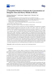
Figure 5. Mode shape of out-of-plane wall for H = 5.6m, a = 8m, b = 8m, t = 0.625m: (a) minimum (tension) and (b) maximum (compression) principal curvature contours. The tension stresses indicate the expected inverted-Y yield line mechanism. Using the expressions for the czz, cyy and cyz curvatures we can estimate the principal curvatures c1 and c2 anywhere on the wall (Timoshenko[10]):
c1, 2 =
c yy + c zz
2
c − c zz ± yy 2
2
+ c 2yz
(22)
Contour plots of the principal curvatures appear in Fig. 5, where it becomes obvious that the mode shape selected allows the formation of a yield line mechanism that is in agreement with classic plate theory. This allows us to define additional failure modes for the structure based on the out-of-plane wall curvatures reaching the limiting curvatures defined earlier. Thus, we propose that a local or global mode of failure may defined by the appearance of tension cracks along at least ρ fraction of the height. For the critical top half of the wall where tension cracks will appear first, c2 is completely dominated by cyy. For most of the lower half, cyy remains a good indicator of the maximum value of the c2 curvature at a given value of z. Thus, it is reasonable to use cyy as a proxy for c2 to check the condition of the wall. This can be accomplished via the simple Eq. 20 by checking for cyy(y,z) = φlim at the vertical midline of the wall, i.e., at y = b/2, and for a given portion of the wall. Since the
Dimitrios Vamvatsikos, and Stavroula J. Pantazopoulou. maximum (in absolute terms) c2 or cyy always appears at the midcrest and it is generally decreasing with decreasing z, we can find the extend of cracking or failure by only checking at a given value of z. Thus, if cyy(y, z) = φlim for y = b/2, z = ρH, where ρ ∈ [0,1] , then to a good approximation, the entire midline above this point will have cracked or failed. Then the corresponding midcrest displacement may be estimated from Eq. 20 as:
δ tot = ϕ lim
2 ( 2 + 2 )b 2 . 9π 2 ρ 2 ( 2 − ρ )δ F
(23)
Thus, based on the concepts of shear and bending failure, we may define two limit-states that will characterize the performance of the system: 1) LS1 is akin to an Immediate Occupancy limit-state. Violating it means that the building will be yellowtagged (or worse) in a post-earthquake damage assessment. It occurs whenever the out-of-plane walls have developed cracks, i.e., exceeded φcr in the top 50% of their height (ρ = 0.5 in Eq. 23) or when the shear strain of the in-plane wall exceeds the yield shear strain (Eq. 13). 2) LS2 is defined as a Collapse Prevention limit-state. Exceeding this limit-state will signify that the building is close to collapse and it will be red-tagged if it is still standing. It happens when the along-y curvature of the out-of-plane wall has formed a near complete yield line mechanism, exceeding the ultimate curvature φu for at least 50% of its height (ρ = 0.5 in Eq. 23), or when the shear strain of the inplane wall is greater than the ultimate shear strain (Eq. 14). Apparently we have skipped the definition of an intermediate limit-state, akin to a Life Safety performance level. The reason is the low ductility of such heritage masonry buildings where they either survive the earthquake with light damages or suffer near total destruction. 6
CONCLUSIONS
A simplified methodology has been presented for the seismic vulnerability evaluation of a group of historical structures. Using a simple mechanical model with appropriate probabilistic characterization based on existing literature, inventory data and expert opinion, we are able to provide the groundwork for deriving fragility curves for a relatively homogeneous ensemble of stone masonry structures. The end result is a realistic representation of the vulnerability of the building ensemble that will be able to incorporate both aleatory randomness and epistemic uncertainty in a concise and accurate way, allowing a fast and reliable estimate of the performance of the historical core of heritage cities. REFERENCES [1] Tanrikulu, A.K., Mengi, Y., and McNiven, H.D. (1992), “The nonlinear response of unreinforced masonry buildings to earthquake excitation”, Earthquake Engineering and Structural Dynamics, 21, 965–985. [2] D’Ayala, D., Spence, R., Oliveira, C., and Pomonis, A. (1997), “Earthquake Loss Estimation for Europe's Historic Town Centres”, Earthquake Spectra, 14, 4, 773–793. [3] D’Ayala, D., and Speranza, E. (2003), “Definition of Collapse Mechanisms and Seismic Vulnerability of Historic Masonry Buildings”, Earthquake Spectra, 19, 3, 479–509. [4] Cornell, C.A., and Krawinkler, H. (2000), “Progress and challenges in seismic performance assessment”, PEER Center News, 3, 2, URL http://peer.berkeley.edu/news/2000spring/index.html, [Oct 2009]. [5] Vamvatsikos, D., and Pantazopoulou, S.J. (2010), “Simplified vulnerability assessment of historical city cores — the example of the city of Xanthi”, Proceedings of the 9th US National Conference on Earthquake Engineering, Toronto, Canada. [6] Tastani, S., Papadopoulos, M., and Pantazopoulou, S. (2009), “Seismic response of traditional masonry buildings: parametric study and evaluation”, Proceedings of the 1st International Conference on Protection of Historical Buildings, Rome, Italy. [7] Vintzileou, E. (2008), “The effect of timber ties on the behaviour of historic masonry”, ASCE Journal of Structural Engineering, 134, 6, 961–972. [8] CEN (2004), Eurocode 8: Design of structures for earthquake resistance, Part 3:Assessment and retrofitting of buildings. Comité Européen de Normalisation, Brussels. [9] Clough, R.W., and Penzien, J. (1975, 1993), Dynamics of Structures, Mc Graw Hill, N.Y. [10] Timoshenko, S., and Woinowsky-Krieger, S. (1987), Theory of Plates and Shells, McGraw-Hill, NY. [11] Chopra A.K. (1995), Dynamics of Structures: Theory and Applications to Earthquake Engineering, Prentice-Hall, Englewood Cliffs, NJ.