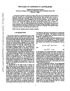
Development of an Automated Multi-level Car Parking System V. Padiachy, J. Kumar, A. Chandra, K. Prakash, P. Prasad, H. Prasad, U. Mehta, K. A. Mamun, P. Chand School of Engineering and Physics, University of the South Pacific, Suva, Fiji Email:
[email protected] Abstract – With the increased development of mechatronics system and scarcity of land space, this paper introduces and prospects an engineering application to solve or reduce the mentioned issue by designing and implementing automated multi-level car parking system. The paper discusses the research antiquity, brief model methodology, software implementation, design analysis and recommendations.
Keywords – mechatronics, multi-level car parking, automation. I.
INTRODUCTION
The number of cars on the streets of Fiji is increasing alarmingly as there has been an increase in the variety of motor vehicles which also have low prices. Fiji, being a third world country, is facing problem in catering these vehicles in available parking spaces and a time may come when we may not be able to cater for vehicles any longer. A prominent example of this is the parking spaces at Damodar City (Suva, Fiji) where parking space is limited compared to the vast number of vehicles which require a parking area. Vehicle parking is becoming a major problem nowadays. As the population is increasing, the number of vehicles on the roads is also increasing leading to an insufficient area to park these vehicles. This creates a greater problem when people end up parking cars on roads which causes traffic jams. Multi-storied car parking system will help in parking large number of vehicles in a smaller area. This Automatic Car Parking System enables the parking of vehicles, floor after floor and thus reducing the space used. Also automating this will help in less manual intervention and thus will lead to fewer problems. Such a system has been proposed and designed in this project. Additions are made to the existing systems to ensure maximum space utilization. To serve this purpose, parking slots are assigned inside the multi storied structure depending on the size of the car. Implementation
of the design was carried out in AUTOCAD with hardware being introduced at input and output stages. Programming in AUTOCAD is done in a way which is user friendly and can be handled by an inexperienced operator. II. LITERATURE REVIEW The endless search for free spaces in a car park is a burden for any driver nowadays since vehicles are a predominant mode of transportation. With rising number of vehicles and dwindling parking spaces, vehicles parked along the road and even on sidewalks have become fairly common phenomena. With these parked vehicles encroaching on road space and pedestrian space, traffic congestion and accidents are inevitable. A well-organized parking system which makes maximum use of available space offers a solution to this situation. There are two categories of parking systems which have been identified. These are traditional parking systems and multistoried parking system. In traditional parking systems, vehicles are parked in perpendicular or parallel fashion. With no safety against the protection against atmospheric conditions, it is not a space efficient system either. Multistoried parking systems are preferred since they multiply parking capacity of a given area [1]. Various floors are present for parking the vehicles with ramps and staircases provided for moving between floors. There are various types of existing systems that are applied in many countries to improve parking facilities for crowded areas [1-6]. This review identifies a few of them. To begin with, Lot-specific systems use signs to provide parking information that typically contain simple directions to parking facilities and advise for drivers to find the available space using signs that typically have both passive and active components [2]. The passive component provides simple directions to parking facilities, such as with an arrow. The active component
supplements the passive component to advise the traveler of the availability of spaces at the facility. The advantage of this type of system is that it displays the number of available spaces in the entrance of car park, in the entrance of each level and at the end of each aisle. It also displays the directional signage for each aisle, showing the driver which direction to follow. Different colored LED lights help the drivers to differentiate between spaces (reserved, occupied, vacant or handicapped). It also avoid improper parking. A second type of parking system is the Floor-Aisle and Space specific Parking Information Systems. These provide information about the number of places in the car park, including both full and empty places. They provide more detailed information and are placed in the entrance of car park, on each floor, at the beginning of every aisle and even in front of every individual place of parking. This system helps the parking management to manage the parking inventory, allows them to obtain accurate up-to-the-minute data and helps keep the car park open to its true capacity [3]. This system has certain advantages and this includes reduced vehicle build-up at entries, exits and aisles, a shorter vacant slot search times resulting in less vehicle emissions. It also avoids congestion and unwanted traffic with the help of effective signage within the car parks. Moreover, at shopping centers, customers can spend more time shopping rather than looking for parking space and a convenient parking experience will be valued. However, the main drawback of this system is that from a customer’s perspective, there is n o opportunity to reserve a place in advance which may lead to congestion in front of some available spaces. A final type of parking system that could be identified was the Online Reservation Systems. This is one of latest trends in parking management system, this facility enables the driver to reserve a parking place in any multi-story park through the website or mobile phone application, and pay online in order to reserve that place, thus they will receive a message containing information about the place of parking in that car park. This mechanism is very useful for reducing the time it takes to find a place. This approach is implemented in many countries such as the U.S. In 2004, Mobile Parking LLC and Spot Scout TM are two companies that offer clients or drivers the chance to check for available spaces in about 400 parking area in 50 cities across the U.S., using their radio, cellular telephone, or computer, it was used to reserve a place in any type of parking area, not only multi- story park [7]. The benefits of this system are that reduced time is spent for parking
spaces and reduced frustration of visitors and easier access to parking place. There is also reduced effort for venue operators in order to satisfy the customer, since they will be responsible for choosing the place not the venue operator. Parking operators will also benefit from increased occupancy and associated increase in revenue as customers will pay for advanced reservations besides the cost of parking [8]. However, there are few drawbacks of this system as it is expensive to implement everywhere, the architecture of the system may require a lot of equipment, which in turn requires a huge budget. It also requires huge amount of time, cost and effort to implement and finally it needs sophisticated and modern technology. From the review of a study by P. Bhauguna (2009) [9], automatic multi-level car parks provide lower building cost per parking slot, as they typically require less building volume and less ground area than a conventional facility with the same capacity. However, the cost of the mechanical equipment within the building that is needed to transport cars internally needs to be added to the lower building cost to determine the total cost. Other costs are usually lower too, for example there is no need for an energy expensive ventilating system, since cars are not driven inside and human cashiers and security personnel may not be needed. A multi-level car park offers the greatest possible flexibility for the realization of optimum parking solution. However to date elevating type parking mechanism not found from the literature. Hence this research focuses on developing such a system which will also increase the parking space. III. PROJECT REQUIREMENTS The need for a solution of a car parking system for various reasons such as; efficient use of space of land, lack of time consumption, secure, environmental friendly and comfortable for the drivers has been discussed. The proposed solution for this problem, is an automated multi-level car parking system. The vehicle parking areas will be elevated to a certain level. A system as such would be inexpensive compared to the normal parking, since the value of land to be used for normal car parks would add expense to its total cost, this is because the value of land increases as days go by. The requirements that our solution meets are: optimal utilization of space
Low maintenance cost Low operational cost Low constructional cost Secure Environmental friendly Comfortable for the drivers Automated
The proposed system will employ three aspects of mechatronics, the use of actuators, sensors and transducers. IV.
METHODOLOGY
A. Hardware 1. Identifying and sketching the solution The best way to put any ideas in action is to sketch it up. Thus all the structures and the components needed were either sketched or listed down. In this research a scale down 3 level parking space model was considered during the design phase. A thorough research work was done to identify the appropriate size that is needed for a vehicle to be parked in, depending on the size the uncertainties were also considered to prevent the vehicles from getting damaged. First of all, by looking at the size of the car that will be used as a model for hardware development this research multiple toy car were used during the experimental stage and came up with dimensions of the car park area (sketched shown in Fig. 1).
Fig. 2. Sketch of Lifting Mechanism
A mechanism was designed that is proposed to be used to pick up vehicles and place it in the empty slots available in the cark park, as shown in Fig. 2 above. A plate was designed that will scoop the vehicle from the side and as directed by the micro controller it is going to place the vehicle in the empty slot available. As show in Fig. 2 a pin and rack gear is used to move back and forward and the whole system is connected to a belt drive mechanism which will lift the car and all of this is connected to the axial for easy movement. 2. Drawing the components in AutoCAD and 3D print Structural designs; namely 3 different gears (i.e. Rake & Pinion), a base structure was made for the lifting component to move back and forth and two shafts were for the lifting structure are drawn using AutoCAD. CAD designs of various parts are shown in Fig. 3; which were finally fabricated using 3D printer.
Fig. 3. Auto CAD Designs
Fig. 1. Sketch of Car Park Compartment
3. Construction of parking components Ply wood was used to build the multilevel compartments due to the availability and ease of fabrication. Fig. 4 shows the constructed model of the
multilevel compartments used in this research. Finally a Light Dependent Resistor (LDR) is used in each compartment.
B. Software A program in c language was developed that will lift a vehicle and put it in an empty slot by a push of a button and will also retrieve the vehicle from its compartment by a push of a button for the slot the vehicle is in. For the motor to know when to switch on and off to do the right thing this research used timing sequences. An efficient feature of the PIC micro-controller, timers enabled the model to achieve real time intervals to switch on and off the three directional motors were used. At first all necessary header files, devices, fuses and clock were included. After this all LDR input port with pin number were initialized together with all the variables used.
Fig. 4. Parking Compartment
4. Design and implementation of the horizontal X movement A lead screw was used to cater for the horizontal movements. The threaded lead screw is rotated by the motor. The center of the base is connected to the lead screw. As the lead screw spins the base starts to move. On the other hand the base of the system and the axial column will be mounted. So as directed by the microcontroller the motor will spin to get the vehicle in the right position for parking. 5. Design and implementation of the vertical Y and Z movements For the vertical movement, a motor wa s u s e d to move the ramp up and down. The system or component that will move vertically (i.e. z-direction) is shown in Fig. 5. The platform is connected with a belt to the side of the platform to lift it up and also to move it down. The pinion and rack gear system will move the vehicle in and out, which will be driven by the motor.
Timer 0, 16 bit of Prescaler was used; the reason for choosing timer 0, 16 bit is as this can read values from 0 to 65535. As 8 bit timers can only count values from 0 255 it would not be sufficient enough for counting small to large timing (seconds). When a button is pressed it will either sense by the LDR which compartment is empty t o place car or to which button is pressed for retrieving a car. When it detects an empty space for placing or button pressed for retrieving it enables the timer and calls the timer function. Once conditions are satisfy, it switches motors on and off respectively to carry out the task of placing and retrieving. After doing that it disables the timer and waits for a button to be pressed for its next task.
V.
DESIGN CALCULATION
A. Rack and Pinion Calculations Given below are the calculation for the design of the pinion and rack (Fig. 6 & 7), where all measurements in millimeters. Diameter Pitch (P) = 0.15 Number of teeth (N) = 5 Pressure angle (PA) = 51
1. Pitch Diameter (D) = N/P = 5/0.15 = 32 2. Pitch radius (R) = D/2 = 16 3. Base circle diameter (DB) = D * cos(PA) = 16 x cos(51) = 10 4. Base circle radius (RB) = DB/2 = 5 Fig. 5. Components used for Z Movement
5. Addendum(a) = 1/P = 6.7
6. Dedendum (d) = 1.157/P = 7.7
7. Outside diameter (OD) = D + 2 x a = 32 + (2x6.7) = 45.3
8. Outside radius (OR) = R + a = 16 + 6.7 = 22.7 9. Root diameter (DR) = D – (2xd) = 32– (2x7.7) =16.6 10. Root radius (RR) = R – d = 16 – 7.7 = 8.3
This is when the LDR is uncovered and when LDR resistance is about to increase the value of output voltage changes. The resistors rating is 82 kilo ohms and all the LDR are of same value. The above circuit was interfaced with the PIC 18F8722 and it is used in this prototype to sense the occupancy of car in the compartment. Fig. 8 shows the LDR interfaced circuit with PIC 18F8722, during the experiment.
Fig. 6. Pinion Design
Fig. 8. Voltage Divider Circuit testing on bread board
C. Timer 0, 16 bit Sample Calculation Using timer 0- 16 bit, Prescaler 16 and clock frequency of 20 MHz the following times and counts are produced. For 20 MHz clock frequency, we get, Fig. 7 Rack Design
B. LDR Interfacing LDR is used to sense the occupancy of the car in the compartment. The LDR is connected at the base of each compartment and a light is placed on top. When the car is parked, the LDR gets covered and tells the system which level compartment is full and which one is available. According to calculation, the required values of resistors were used with the LDRs. When LDR is left uncovered, in light the resistance it has 10 kilo ohms and when it is covered the resistance it has 80 kilo ohms. A voltage divider circuit with LDR was connected. The calculated output voltage is 0.5 volts. The calculation is as follows.
20 𝑀𝐻𝑧 4
= 5 MHz
Time Period =
1 5 𝑀𝐻𝑧
= 0.2 us
Prescaler Period = 0.2 us * 16 = 3.2 us. Overflow Period = 3.2 us * 65535 = 0.209712 Each Flow time is 0.209712 s To get delay for 1 s, we need To get delay for 5 s, we need
1 0.209712 5 0.209712
= 4.78 = 5 counts = 23.84 = 24
counts To get delay for 10 s, we need counts
10 0.209712
= 47.68 = 48
VI. DESIGN IMPLEMENTATION The overall circuit diagram (Fig. 9) is divided into two sections known as placing circuit and retrieving circuit. Firstly, the placing circuit explains how the empty slots in the compartment are detected and how the hardware design operates to place the vehicle in the detected empty slots. The placing circuit is operated through microcontroller 2 as illustrated in the block diagram. Inputs t o this microcontroller are 6 LDR sensors to detect the empty slot and a push button for placement to begin. The outputs connected to this microcontroller are DC motor 1,
Fig. 9. Overall Circuit Diagram
DC motor 2 and DC motor 3 that control X, Y and Z movement respectively. As the driver or the security in charge press the button the empty slots will be detected. The slots are detected through LDR sensors which are placed on the base of each slot in the compartment. Once an empty slot is detected the motors 1, 2 and 3 are turned on accordingly for X, Y, Z movement. Once the vehicle is parked the owner is indicated the slot number, where his vehicle is parked in through the display.
Secondly, the retrieving circuit explains how the parked vehicle is removed from the compartment. Retrieving circuit is operated through microcontroller 1 as shown in the system block diagram. Inputs to the microcontroller are the 6 push button and the outputs are the three DC motors. In order for the vehicle owner to remove his vehicle from the compartment, he/she has to press the push button corresponding to the slot his/her vehicle is parked in earlier. Once the button is pressed the DC motors are turned on accordingly for X, Y and Z movement to remove the vehicle from the slot. Overall design is shown in Fig. 10.
Fig. 10. Complete model of multilevel cark park system.
VII. CONCLUSION The automated multi-level car park designed in this paper represents a new parking innovation technique. As documented, due to less land availability, parking is a growing concern in the Fijian or a city context. A multilevel car park offers the greatest possible flexibility for the realization of optimum parking solution. However, this prototype can be implement in real; using more powerful motor for faster movement, limit switches for accuracy, bearings and appropriate materials for less friction, more rigid structure for more stability, closed system to reduce noise pollution and display system to show parking availability. ACKNOWLEDEGEMENT The research team would like to thank the School of Engineering at the University of the South Pacific for funding this research project.
REFERENCE [1] S. Lee, D. Yoon, A. Ghosh, “Intelligent Parking Lot Application Using Wireless Sensor Networks”, International Symposium on Collaborative Technologies and Systems, pp.48-57, 19-23 May 2008. [2] J. Takahashi, K. Sekiyama, T. Fukuda, “Cooperative Object Tracking With Mobile Robotic Sensor Network”, Distributed Autonomous Robotic Systems. Springer, Berlin, pp 51–62, 2009. [3] H. G. Jung, D. S. Kim, P. J. Yoon, J. Kim, “Uniform User Interface for Semi-Automatic Parking Slot Markings Recognition”, IEEE Trans. Veh. Technol., vol.59, no.2, pp 616–626, Feb. 2010. [4] L. Wenghong, X.Fanghua, L. Fasheng, “Design of Inner Intelligent Car Parking System”, International Conference on Information Management, Innovation Management and Industrial Engineering 2008. [5] E. M. T. M. Y. Idris, "Smart Parking System," Journal of Information Technology, pp. 114-127, 2009. [6] T. Moran, J. Meiners, “The Arrival of Problem Free Parking”, Autom. News Eur., vol.11, no.24, pp. 8, Nov. 2006. [7] K. A. A. Albagul, "Design and Fabrication of an Automated Multi Level Car PArk System", Manufacturing Engineering, Automatic, 2014. [8] E. M. T. M. Y. Idris, "Smart Parking System", Journal of Information Technology, pp. 114-127, 2009. [9] P. Bahuguna, “Multi Level Parking”, Final Year Project report, College of Engineering Roorkee, 2009.