Proceedings of the World Congress on Engineering 2012 Vol II WCE 2012, July 4 - 6, 2012, London, U.K.
Development of an Educational Virtual Mobile Robot Simulation Y. Yusof, M. F. Abu Hassan, N. J. Mohd. Saroni, and W. M. F. Che Wan Azizan Abstract—Nowadays robot are widely used in many fields. Recognizing its importance, robotics course has been included as part of Engineering and Computer Science undergraduate curriculum. Teaching students using physical robots can be an expensive task. Therefore the alternate solution is to utilize computer simulation. This paper describes our experience on developing an educational prototype mobile robot simulation using Microsoft Robotics Studio (MSRS) utilizing its Visual Simulation Environment (VSE) starts from creating the mobile robot, integrating into the environment and controlling the behaviour.
situation can be precisely generated to trigger a known error and later check the solution. In addition to these, all vital data can be logged. This gives researchers and students an understanding of inconsistencies in their algorithm performance. B. MSRS Simulation In this paper we present the feasibility studies done on MSRS as a tool and platform for building a customized educational simulation based on an actual mobile robot; the
Index Terms—Microsoft Robotics Studio, robot simulation, robotics, virtual environment
I. INTRODUCTION
T
HE robotics industry emerged and is developing in much the same way that the computer business did 30 years ago; it is envisioned that in the near future robotic devices will become a nearly ubiquitous part of our day-today lives [1]. Apart from that, robotics has been shown by a number of researchers to be motivating and beneficial in teaching science and technology [2]. Teaching students using physical robots can be an expensive task and only limits the usage of robot only during lab hours. A. Robot Simulation Generally, simulation plays an important role in the field of robotics. Simulations permits inexpensive and less time consuming experiments. Countless number of experiments can be conducted, modifications in the robots dynamics can be made, and changing and rebuilding experimental environment can be done in the simulation. These allow researchers and students to perform exhaustive experiments without the worry of damaging the actual robot. The robot can be tested, and the virtual model can be finely tuned to replicate similar performances on equivalent tests. Another important attribute of simulations is repeatability; which allows for simplified debugging because the identical Manuscript received March 23, 2011. Y. Yusof is a lecturer with the Universiti Kuala Lumpur Malaysia France Institute, 43650 Bandar Baru Bangi, Selangor, Malaysia (phone: +603-8926-2022; fax: +603-8925-8845; e-mail:
[email protected],edu.my). M. F. Abu Hassan is a lecturer with the Universiti Kuala Lumpur Malaysia France Institute, 43650 Bandar Baru Bangi, Selangor, Malaysia. (email:
[email protected],edu.my). N. J. Mohd. Saroni is a BET Industrial Automation and Robotics student at Department of Industrial Automation, Universiti Kuala Lumpur Malaysia France Institute. W. M. F. Che Wan Azizan is a BET Industrial Automation and Robotics student at Department of Industrial Automation, Universiti Kuala Lumpur Malaysia France Institute.
ISBN: 978-988-19252-1-3 ISSN: 2078-0958 (Print); ISSN: 2078-0966 (Online)
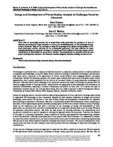
Fig. 1. MFIBots – physical model of simulated mobile robots.
MFIBots shown in Fig. 1. The focus will be on utilizing and exploring the MSRS components and features in developing mobile robot simulation. II. RELATED WORK Almost every field in engineering make use of and reap the benefits of computer simulations. Robotics is no exception. At present there are several robot simulators ranging from open source and free to commercial and proprietary software. The level of simulation differs considerably among the simulators. Some allows the user to specify robot behaviours or plans, while others can be used to examine the exact path trajectory driven by a robot. A superior robot simulator must both support simulation and allow robot to interacts with the environments i.e. permit sensing and react to its environment changes through sensors and actuators. Followings are a short survey done on simulators offering these features. A. Survey of Robot Simulators Urban Search and Rescue Simulation (USARSim): A mobile robot simulator initially developed to focus on differential drive systems for wheeled robots [3]. The simulation attracted lots of interest with wide community support and the initial platform was enhanced significantly. At present, the available version supports wider range of robots and sensors, which includes underwater vehicles, legged platforms, and humanoids. Users of this simulation
WCE 2012
Proceedings of the World Congress on Engineering 2012 Vol II WCE 2012, July 4 - 6, 2012, London, U.K. must learn Unrealscript code, a proprietary object oriented language with syntax resembling C++ and Javascript. Player/Gazebo: This simulator was developed at the USC (University of Southern California) [4, 5]. The Player project provides a network server platform for programming real robots and is one of the widely used in the robotics community. Gazebo is a 3D simulator with the ability to simulate several Player-based Robots and the simulation environment is built on top of OGRE (Object-Oriented Graphics Rendering Engine). Gazebo can be standalone, or accessed through the Player server. Coupled with Player, Gazebo offers a great multi-robot simulation in 3D environment. Player/Gazebo components are available under the GPL license. They both are a powerful package that relies on several complex components and thus require some time to learn. WebotsTM [6]: A commercial simulator runs on Windows, Linux and Mac OS X which is intended for researchers and teachers interested in mobile robot. Developed by Swiss Federal Institute of Technology in Lausanne (EPFL) and initially used for mobile robotics prototyping simulation, allows transfer of simulated algorithm to physical Kephera robots only. Later, it offers support also for other robot platforms like the Sony Aibo, a humanoid platform, and several differential drive mobile robots. It also allows custom robot design to be simulated using a specialized authoring tool. The cost of purchasing is the limitation of using this software is due to its proprietary nature. EyeSim - EyeBot Simulator [7]: A multiple mobile robot simulator. The environment modelling is 2½D, while 3D sceneries are generated with synthetic images for each robot’s camera view of the scene [7]. Robot application programs are compiled into dynamic link libraries that are loaded by the simulator. A virtual control panel (equivalent to the LCD display and buttons on the real EyeBot controller) allows communication via the robot's user interface. The simulator is freely available over the internet. It does not allow user to design custom robot and the sensors availability only limited to what’s being offered inside the simulator. Microsoft Robotic Studio (MSRS): A windows based simulator which utilizes Ageia’s PhysX physics engine. Simulations can be programmed with MS Visual Studio C#. Key advantages of MSRS are the concurrency and coordination run¬time (CCR) and decentralized software services (DSS) which supports distributed robotic applications. The subsequent section will further discuss on MSRS simulation features.
Concurrency and coordination runtime (CCR): A feature that addresses the issue of concurrencies. The CCR is a library of functions—sequences of software code that perform specific tasks—that makes it easy to write multithreaded applications that can coordinate a number of simultaneous activities [2]. It was designed to help programmers take advantage of the power of multicore and multiprocessor systems which is also ideal for robotics. Decentralized software services (DSS): DSS provides the runtime environment that allows services to exchange messages regardless of where they are located on the network. Since DSS allows software components to run in isolation from one another, if an individual component of a robot fails, it can be shut down and restarted—or even replaced—without having to reboot the machine [2]. Microsoft Visual Programming Language (VPL): A visual programming tool for creating and debugging robot applications which utilizes web-based and windows-based interfaces. The VPL (Fig. 2) allows for a LabView like graphical modelling approach to create the entity behaviours that belong to each entity i.e. sensors, actuators. The developer uses the palette of objects and behaviours then ―drags and drops‖. The visual objects are connected together and set the exposed properties correctly in order to program a robot; the developer can create various distinct entity behaviours.
Fig. 2. VPL example in MSRS [13].
Visual Simulation Environment (VSE): 3D simulation environment (Fig. 3) which includes hardware acceleration. The simulation environment is enabled by AGEIA PhysX engine; a real world physics simulation engine that allows near to real-world modelling and response of the robots will take place in this virtual environment. Robot can be initialized in a virtual world; move and physically respond to the virtual environment as if it was deployed in a real world.
III. MICROSOFT ROBOTICS DEVELOPER STUDIO MSRS is a MS Windows-based environment for robot control and simulation, which aimed at academic researchers, hobbyist, and commercial developers and handles a wide variety of robot hardware [8]. Apart from being able to work in familiar MS Windows environment, MSRS is programmed using C# and runs inside Visual Studio Express Integrated Development Environment which are free. This makes the development and debugging much easier. Besides that, MSRS offers features which include:
ISBN: 978-988-19252-1-3 ISSN: 2078-0958 (Print); ISSN: 2078-0966 (Online)
Fig. 3. An example of 3D VSE in MSRS [12].
WCE 2012
Proceedings of the World Congress on Engineering 2012 Vol II WCE 2012, July 4 - 6, 2012, London, U.K. Existing robots and components: MSRS allows straightforward access to multiple simulated robots such as KUKA, LegoMindstorm, various sensors and actuators. Examples of these sensors are the Laser Range Finder (Fig. 4), the Sonar Range Finder, the wheel motor drives, articulated joints and GPS location devices.
Fig. 4. Sensor specification and mobile robot simulation [10].
A. MSRS Underwater Robot Simulation A similar work was done to study underwater robot simulation with ultimate goal of performing simulation of land, air and sea robotic [9]. This project uses MSRS features on integrating 3D robot models designed using CAD (Computer Assisted Design) software. The robot model in 3D design and the simulation result can be seen in Fig. 5 and 6. This project highlights the process and problems developing the underwater virtual simulation using MSRS.
IV. INITIAL EXPERIMENTS A simple 3D model to represent mobile robot model was designed using CAD software, integrated into simulation environment and then simulates the robot motion using existing MSRS components. The conducted experiments were as follows: Designing 3D model: MSRS only supports a specific 3D format i.e. COLLADA to be imported in the environment. A simple 3D model of a box to represent a mobile robot model was made using CAD software. The model was converted into COLLADA format and then imported into the MSRS environment. Creating simulation environment: A manifest had to be created before attaching any elements into the environment. The elements will be added by writing program using the C# (C Sharp) software language. Fig. 7 shows the example of the program to create a skydome and light source in the VSE. The result of integrating the mobile robot into VSE is shown in Fig. 8. //Add a SkyDome SkyDomeEntity sky = new SkyDomeEntity (“skydome.dds”, “sky_diff.dds”); SimulationEngine.GlobalInstancePort.Update(view) ; //Light source LightSourceEntity sun = new LightSourceEntity(); sun.State.Name = “Sun” sun.Type = LightSourceEntityType.Directional; sun.Color = new Vector4(0.8f,0.8f, 0.8f, 1); sun.Direction = new Vector3(0.5f, -.75f, 0.5f); SimulationEngine.GlobalInstancePort.Insert(sun Fig. 7. Adding the simulation environment code. );
Fig. 8. Simple robot simulation. Fig. 5. 3D model of submarine [9].
Creating motion: The motion properties had to be inserted in order to enable the robot movements. After editing the properties, a controller was added for controlling the simulation robot. Fig. 9 shows the virtual and actual controller.
Fig. 6. Under water robot simulation in MSRS VSE [9].
ISBN: 978-988-19252-1-3 ISSN: 2078-0958 (Print); ISSN: 2078-0966 (Online)
WCE 2012
Proceedings of the World Congress on Engineering 2012 Vol II WCE 2012, July 4 - 6, 2012, London, U.K. private void PopulateWorld() { AddSky(); AddGround(); AddMfiBot(); AddBox(); } Fig. 12. C# code snippet: Adding the sky, ground, MFIBot and a box into VSE.
Fig. 9. Virtual and actual Xbox 360 robot controller [13]
V. DESIGNING VIRTUAL 3D MODEL AND INTEGRATION IN MSRS After the initial experiments, measurement i.e. heights, wheel size, weight and etc. were taken from the actual mobile robot before creating the 3D model. Since MSRS only supported certain format, the modelling software Solidworks was used. The mobile robots parts were created in this software and then assembled to form a complete 3D model. Fig. 10 shows the completed 3D mobile robot model designed using Solidworks. The comparison between the completed 3D virtual mobile robot and actual model is shown in Fig. 11.
// specify a default mesh State.Assets.Mesh = "Mfi-bot.bos"; Fig. 13. C# code snippet: Adding the MFIBot ―.bos‖ into VSE.
Fig. 14 shows the final representation of 3D MFIBot robot model simulated in MSRS VSE. Adding controller and motion properties by configuring DSS; the simulated robot can be controlled using Xbox 360 controller. A test was performed using Xbox controller to drive the robot forward. The robot falls after colliding with a wall; this is shown in Fig. 15.
Fig. 14. Final representation of 3D mobile robot model in MSRS VSE.
Fig. 10. Designing 3D mobile robot model using Solidworks.
Fig. 15. Simulation result: Robot falls after colliding with the wall. Fig. 11. Comparison between virtual 3D and actual mobile robot model.
In order to import the completed 3D robot model into the MSRS VSE there few steps to be followed, which are: a) 3D robot model was designed using Solidworks, it has to be saved into Colada format in the form of ―.dae‖ file; b) the Colada format file will be converted into ".obj", a Wavefront object simulation mesh; c) Using "obj2bos.exe" converter that comes with MSRS, the ".obj" to ".bos" file converter tool converts Object simulation mesh file into an optimized binary file; d) write C# program to customize the simulation environment as shown in Fig. 12 and 13.
ISBN: 978-988-19252-1-3 ISSN: 2078-0958 (Print); ISSN: 2078-0966 (Online)
A. Encountered Problems Comprehensive study was conducted before using MSRS. It was assumed that there will be no major problems in developing robot simulation using VSE. The first problem encountered in the VSE simulation is sinking wheel as shown in Fig. 16. The MSRS simulation engine uses a right-handed coordinate system, which affects the direction toward which the Z axis points. Therefore, during the design, both Solidworks and VSE must use adopt same coordinate system and the most bottom part of the
WCE 2012
Proceedings of the World Congress on Engineering 2012 Vol II WCE 2012, July 4 - 6, 2012, London, U.K. robot i.e. the wheel must be placed on the x, y plane where z axis is equal to 0.
Fig. 16. Wheel sinking into the ground
The second problem encountered in the VSE simulation is missing texture and color as shown in Fig. 17. This can be solved by editing the ―.obj‖ format file using Blender, cross platform suite of tools for 3D creation to include colour and texture information. Fig. 18 shows the edited 3D model in Blender.
was created and integrated into the simulation. In the current development stage, the virtual robot utilizes existing MSRS APIs and components and there are no sensors attached to the robot. For future development the virtual robot in the MSRS will be enhanced. The customized manifest and controller objects to allow controlling via VPL by the means of writing programs will be created. Apart from the controller, sensors will be attached to the virtual robot. This will be done by creating sensor objects. Once the enhancement has been accomplished, the designed simulated mobile robot can be programmed to simulate real world activities and to be used for teaching robots. The MSRS has great potential in becoming one of the preferred tools for mobile robot simulation. It is packed with lots of useful and easy to learn features. It has rapid prototyping capabilities, varieties of actual robots model and virtual sensors which can be quickly deployed for real world simulation. REFERENCES [1]
[2] [3]
[4]
[5]
[6]
[7]
[8] Fig. 17. Missing texture and colour information after inserting 3D model in VSE.
[9] [10]
[11]
[12] [13]
Beer RD, Chiel HJ, Drushel RF, ―Using autonomous robotics to teach science and engineering,‖ Communication ACM 42(6), pp. 85-99, 1999. Bill Gates, ―A Robot In Every Home,‖ Scientific American, pp. 5865, December 16, 2006. Benjamin Balaguer, Stephen Balakirsky, Stefano Carpin, Mike Lewis and Christopher Scrapper, ―USARSim: a validated simulator for research in robotics and automation,‖ IEEE International Conference on Robotics and Automation, 2007. B. Gerkey, R. T. Vaughan and A. Howard, ―The Player/Stage Project: Tools for Multi-Robot and Distributed Sensor Systems,‖ Proceedings of the 11th International Conference on Advanced Robotics, 2003. N. Koenig and A. Howard, ―Design and Use Paradigms for Gazebo, An Open-Source Multi-Robot Simulator,‖ IEEE/RSJ International Conference on Intelligent Robots and Systems (IROS), Sendai, Japan, 2004. Michel, O, ―Webots: Professional Mobile Robot Simulation,‖ International Journal of Advanced Robotic Systems, 2004, vol. 1, num. 1, pp 39-42. Bräunl, Thomas, Embedded Robotics: Mobile Robot Design and Applications with Embedded Systems. Springer; 2008, ch. 13, pp. 171 172. Kyle Johns, Trevor Taylor, ―Professional Microsoft Robotics Developer Studio,‖ Wrox, 2008. John Prevost, "Simulation of Underwater Robots using MS Robot Studio©,‖ IEEE Xplore, 2008 Haoxiang Lang, Ying Wang, de Silva, C.W., ―Mobile robot localization and object pose estimation using optical encoder, vision and laser sensors,‖ IEEE Xplore, 2008. W. T. Tsai, Qian Huang, Xin Sun, ―A Collabrative Service Oriented Simulation Framework with Microsoft Robotics Studio, ― IEEE Xplore, 2008. MSDN.com. (2010, June). Microsoft Robotics Blogs [Online]. Available:http://blogs.msdn.com/msroboticsstudio/default.aspx?p=4. Microsoft.com. (2010, June), Overview: Microsoft Robotics Developer Studio 2008 (RDS) [Online]. Available: http://msdn.microsoft.com/en-us/library/bb483024.aspx.
Fig. 18. Re-editing 3D model using Blender to include colour and texture information.
VI. CONCLUSION AND FUTURE WORKS The initial experiment was successfully conducted. A simple 3D box to represent the mobile robot was created and integrated into MSRS VSE. Using VPL the movement of the 3D mobile can be controlled. Then a more realistic mobile robot model taken from the actual robot specification
ISBN: 978-988-19252-1-3 ISSN: 2078-0958 (Print); ISSN: 2078-0966 (Online)
WCE 2012