of the servo controller. This servo controller contains a motion profile generator that calculates velocity, acceleration and position values for trajectory planning. It.
STR/03/041/MECH
Development of an Integrated Servo-Controller W. H. Chen, T. J. Teo, W. Lin, G. L. Yang and E. Ho Abstract – This report focuses on the development of an integrated servo-controller (ISC) for servomotors. Comprising of mainly servocontroller and servo-amplifier, this ISC is capable of controlling a wide range of servomotors to perform complicated tasks. Hence, integration of this ISC with a servomotor forms an intelligent modular actuator (IMA) that is essential to modern manufacturing industries. The development of such an ISC involves two major tasks. First, designing the hardware of a compact-sized and highly compatible ISC. Second, developing the software functions to facilitate its functionalities and capabilities. The developed ISC hence forms an integrated-servo-control module, which determines the capability, functionality, flexibility and responsiveness of these IMAs.
controllers and other electronics devices, such as, servo-amplifiers, feedback circuits, etc. A variety of IMAs have been developed in recent years, including, SmartMotor™ by Animatics [6], PowerCube by Amtec [7], etc. The capabilities of each IMA are achieved through a builtin ISC. The compatibility of such ISCs was limited as each ISC was designed and configured specifically for an individual IMA. This restriction reduces the flexibility of it being employed for the motion control on various servomotors. The control frequency of these ISCs is also limited by the communication speed established between the host computer and the ISCs. This report mainly focuses on the development of a general-purpose and cost-effective ISC that can be integrated with a variety of servomotors. Results have shown that the developed ISC generates good transient responses and delivers low tracking errors during large trajectory motion. In addition, this ISC allows stand-alone operations, perform interpolation operations and provides a high control frequency. Such an ISC, not only enhances the capabilities of the IMAs, it also directly contributes to the level of responsiveness and flexibility of the MRAS. This allows the MRAS to facilitate the modern manufacturing industries in meeting the market demands efficiently.
Keywords: Integrated servo-controller, Intelligent modular actuator, Modular technology 1
BACKGROUND
In the ever-changing and highly competitive global markets, most products are largely customized with short delivery period and life cycle. Due to such market demands, enhancing the responsiveness and flexibility of the manufacturing systems becomes the main focus for modern manufacturing industries [1-2]. As a result, the concept of modular reconfigurable automation systems (MRAS) was introduced to address the new challenges in modern manufacturing system [3].
2
OBJECTIVE
The main objective is to develop a generalpurpose and cost-effective ISC for the IMAs. The two major issues addressed in this development are, the hardware design and software programming for the ISC.
The MRAS are mainly comprised of changeable modules, such as actuator, sensor, conveyor, etc. Such modules can be rapidly assembled and configured into a variety of manufacturing systems [4]. An intelligent modular actuator (IMA) is the key module that determines the level of responsiveness and flexibility of these MRAS. Such an IMA is formed through an integration of both an integrated servo-controller (ISC) and a servomotor.
3
METHODOLOGY
3.1
Hardware design
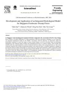
The hardware components of the ISC consist of a servo controller, Pulse-Width Modulated (PWM) power drivers, current detect and feedback circuits, I/Os and watchdog circuits. The communication between the host computer and the servo controller is through an asynchronous serial port. A network port is integrated for communication between multiple ISCs. Fig. 1 illustrates the hardware architecture of ISC.
An ISC is the key component of an IMA that determines its capabilities, such as, performing low-level motion control, communication with the host computer, etc. This results in the advancement of an actuator towards an intelligent and distributed module [5] or an IMA. Such ISCs are developed through integration of micro-
1
Development of an Integrated Servo-Controller
PWM power drving and amplification
From sensors
sensor to complete the current detection and feedback loop.
Servo Motor
Host
Watchdog circuit
Host Input Serial Port
Motor amplifier
Servo controller
Positive
Negative
Axis In
Limit switches
Encoder
D/A DAC Output converter
External memory
Parallel-word Input
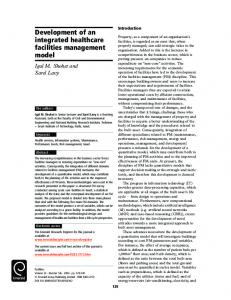
The DC servo controller is basically a chipset that consist of a high-speed digital signal processor based micro-controller produced by Performance Motion Devices, Inc [8]. This servo controller is employed to reduce the substantial software tasks generally inherent by the host’s processor. It contains special on-board hardware that makes it well suited for the task of motion control. Fig. 2 illustrates the block diagram of the servo controller.
User I/O Serial port configuration
Other user devices
Fig. 2. Block diagram of servo controller.
3.1.1.1 Motion profile generator The motion profile generator determines the instantaneous position, velocity and acceleration of the servomotor at an instant of given time. These values are known as commanded values. During a motion profile, some or all of these parameters will change continuously. Once the motion is completed, these parameters remain at the same values until a new motion command is given. The motion profiles are classified into the following:
This servo controller contains a motion profile generator that calculates velocity, acceleration and position values for trajectory planning. It also contains a PID-type servo filter that stabilizes the servomotor output signal. Such a servo filter can produce one of the two types of output: • •
Hall Sensors
Encoder
Fig. 1. Hardware architecture of the ISC.
3.1.1
Micro-Controller
B
Position, velocity and acceleration calculation
PWM Output
External memory
System Clock (20 MHz)
Axis Out
User I/O
Home
Current feedback
Index
Motion profile generation
A
Network port
Servo controller
Analog Inputs
RS232/ RS485 Port
A PWM signal output, or A Digital-Analog-Converter compatible value routed via the data bus to the appropriate Digital/Analog (D/A) converter.
• • •
The servo controller receives the servomotor position in the form of encoder feedback. This feedback is either in incremental encoder input signals or via the bus as parallel word of the input devices. Such an input device can be an absolute encoder, an Analog/Digital converter, a resolver, a laser interferometer, etc. Regardless of the encoder-input mode, the information for the servomotor position is then used to maintain a 32-bit actual axis position counter.
Trapezoidal point-to-point profile S-curve point-to-point profile Velocity-contouring profile
3.1.1.2 Digital PID-type servo filter A servo loop is used to match as closely as possible between the commanded position that comes from the trajectory generator, and the actual servomotor position from the encoder. To accomplish this, the profile generator commanded values is combined with the actual encoder position to create a position error. This error is then passed through a digital PID-type servo filter. Hence, the scaled result of this servo filter calculation is the motor command. This motor command is either a PWM signal to the motor amplifier or a 16-bit input to a D/A converter. Fig. 3 illustrates the structure of the PID-type servo filter.
The servo controller calculates the position, velocity and acceleration of the servomotor through reading the output signals of the encoder. These interpreted output signals will then be taken as the feedback of the servomotor motion and the inputs of the watchdog circuits. The servo controller is also connected with a current
2
Development of an Integrated Servo-Controller
3.1.5
Commanded acceleration
ilim Ki Ref
error
Kp Kd
Z-1
Up to 512KB RAM can be added to provide an external memory to enhance the capabilities of the ISC in three ways:
Kaff
Z-1
derivative time
feedback
+
Kout
Motor bias
X
+
•
Kvff
•
Commanded velocity
•
Fig. 3. Structure of the digital PID-type servo filter.
3.1.2
•
PWM driving and power amplification
To amplify the current of the control signals to drive the amplifier To supply the power to the servomotor through the control of the PWM signal.
3.1.3
Watchdog circuits
External memory also provides storage spaces for the servo controller to capture and store data of up to four parameters continuously during data tracing. The host can then download the captured data by accessing into the external memory. It facilitates users to perform data trace that is useful for optimising the servomotor performance, verifying trajectory behaviour, capturing external sensors data, or monitoring a precise time-based record of the system’s behaviour.
The watchdog circuits can be used for force control applications through current feedback. The circuits will detect and feedback the amount of current continuously to the servo controller. Increasing in the current indicates the increasing of the contact force, while stagnating in the current indicates the opposite. These circuits can also provide circuit protections for the system integrated-components and operation security. The protection functions are listed in table 1.
The most important feature of the external memory is to facilitate the ISC to perform interpolation operations. From the host, a list of dynamics parameters for interpolation, such as, position, velocity, acceleration, etc, will be calculated and downloaded into this external memory. Through this memory buffer, the servo controller will abstract the stored data to perform linear or circular interpolation. Hence, a standalone IMA can also be realized through the used of this external memory.
Table 1. List of protection functions.
No. 1. 2. 3. 4. 5. 6. 7. 8. 3.1.4
Storing the optimised default control parameters of the servomotor Storing the traced data of the selected variables or parameters Storing a list of dynamics parameters for interpolation operations
Optimised default control parameters of the servomotor can be stored into the external memory after verifying through testing and evaluation. For example, mechanical limitations or optimised PID values of a particular servomotor can be stored to provide rapid usage through the ISC. Alteration of the data is also possible to provide flexibility when changing of servomotor is required. Hence, this enables the ISC, to utilize the maximum capability yet maintaining the lifespan, of the integrated servomotor.
Through the PWM driving and power amplification circuits, two functions can be achieved: •
External memory
Protection functions Over current protection Over velocity protection Over heat protection Over voltage protection Under voltage protection Position hard limitation protection 2 I t protection Short circuit protection
3.2
Software programming
The software programming has been divided into two stages. The first stage is to create a portable and generic class of application functions to facilitate programmers in utilizing the ISC for their applications. The second stage is to create a Graphic User Interface based Man Machine Interface (GUI-MMI) for controlling any integrated servomotors through the use of the ISC.
User I/Os
External coordination and sensor messages such as force message can be input through user I/O interface. Users can also get the output messages of the servomotor through this interface. Hence, the ISC receives the capability of external interactions through these interfaces.
3
Development of an Integrated Servo-Controller
3.2.1
Class of application functions
Edit-Setting is an additional interactive feature to provide user the flexibility of modifying the parameters for individual connected servomotor.
This generic class is portable across C and Visual C++ platform. The class consists of all necessary functions that facilitate programmers to create any user interfaces that perform motion control via the ISC, on one or multiple servomotors. Each function of the class performs a specific task through an integration of substantial low-level software functions. Hence, this generic class becomes an inevitable link between the user interfaces and the ISC. 3.2.2
Edit PID parameters Edit Dynamics parameters Identify selected axes
Edit Encoder parameters Edit Breakpoints parameters Edit general settings Save changes for selected parameters of selected axes
GUI-MMI
Fig. 6. Flow chart of edit-setting.
The GUI-MMI is divided into three main structures: Start-Up, Motion-Control and Edit-Setting. Start-Up will be an automated route to facilitate users to establish communication with the connected servomotors via the ISC. Once identifying each servomotor-type, it automatically downloads the optimised default control parameters and displays the status of individual servomotor. Figs. 4, 5 and 6 illustrate the flow charts of individual structure.
4
RESULTS & DISCUSSION
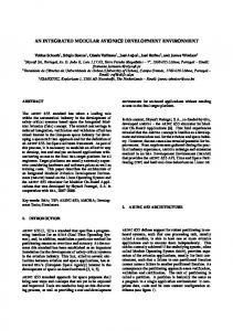
An ISC has been developed through the design and development of both its hardware and software. Fig. 7 shows the picture of a 96mm x 75 mm ISC prototype. Table 2 lists its specifications.
Communication with all connected axes
Identify and display the number of connected axes Identify motor type of each axes Get status of all connected axes Set default axes selection
Display current selected axes status
Fig. 7. ISC prototype.
Get axes status if receive user selection
Table 2. List of specifications. Features Communication modes PWM working frequency Servo loop timing range Multi-axis synchronization Bandwidth
Fig. 4. Flow chart of start-up.
Motion-Control functions as an interactive feature for users to perform motion control on the connected servomotors. It loads the control parameters of individual servomotor into the servo controller to perform the desired tasks.
Range of velocity regulation Motion profile modes
Identified number of selected axes
Start motion for selected axes
Filter modes
Stop motion for selected axes
Emergency stop for all axes
Reset position of selected axes
Reser chip of selected axes
Filter parameter resolution Maximum encoder rate Communication rate Voltage
Fig. 5. Flow chart of motion-control.
4
Specifications Asynchronous serial (RS232/485) 20kHz (crystal frequency: 20MHz) 100µsec to 3355 msec