of Achievements in Materials and Manufacturing Engineering
VOLUME 14 ISSUE 1-2 January-February 2006
Development of an intelligent system for tool wear monitoring applying neural networks A. Antić a, J. Hodolič a, M. Soković b,* a Faculty of Technical Sciences, University of Novi Sad, Trg D. Obradovića 6, 21000 Novi Sad, Serbia & Montenegro b Faculty of Mechanical Engineering, University of Ljubljana, Askerceva 6, SI-1000 Ljubljana, Slovenia * Corresponding author: E-mail address:
[email protected] Received 15.11.2005; accepted in revised form 31.12.2005
Manufacturing and processing ABSTRACT Purpose: The objective of the researches presented in the paper is to investigate, in laboratory conditions, the application possibilities of the proposed system for tool wear monitoring in hard turning, using modern tools and artificial intelligence (AI) methods. Design/methodology/approach: On the basic theoretical principles and the use of computing methods of simulation and neural network training, as well as the conducted experiments, have been directed to investigate the adequacy of the setting. Findings: The paper presents tool wear monitoring for hard turning for certain types of neural network configurations where there are preconditions for up building with dynamic neural networks. Research limitations/implications: Future researches should include the integration of the proposed system into CNC machine, instead of the current separate system, which would provide synchronisation between the system and the machine, i.e. the appropriate reaction by the machine after determining excessive tool wear. Practical implications: Practical application of the conducted research is possible with certain restrictions and supplement of adequate number of experimental researches which would be directed towards certain combinations of machining materials and tools for which neural networks are trained. Originality/value: The contribution of the conducted research is observed in one possible view of the tool monitoring system model and it’s designing on modular principle, and principle building neural network. Keywords: Manufacturing and processing; Machining; Artificial Intelligence methods; Tool wear, Monitoring
1. Introduction 1. Introduction Modern procedures for part manufacturing impose cost reductions that can be realized in the following ways: increasing turning regime, reducing manufacturing time and number of rejects. In order to accomplish that in various processing procedures, extreme efforts of tools and machines are required. Processing tool condition is very influential on reducing rejects
146
Research paper
and standstills in manufacturing, which can directly be seen through geometric, surface and structural properties and characteristics of a processed part. The increase of cutting forces is directly linked to the wear condition of a processing tool which leads to heat increase and hence to structure change of the processed surface of the workpiece and its dimensions. Timely and adequate tool replacement presents a very important component in processing, and therefore in turning, to which a significant attention will be given in this paper. Many
© Copyright by International OCSCO World Press. All rights reserved. 2006
Manufacturing and processing
authors have considered mechanisms influencing the tool wear process in turning. For example, Scheffer et al [1] believe there are two principal characteristics influencing the reliability of turning: cutting speed and value of the force appearing in turning. Researches dealing with this topic have shown that, from the point of optimal time of tool life expectancy, large variations in speed and cutting force are not allowed. Based on experience, it is known that flank wear directly influences the quality of processed surface, and that insert breakage is influenced by crater wear appearing because of diffusion chemical reaction in processing. The experience says that tool wear process moves on continually and gradually, i.e. that the insert wear degree can be determined and one can react on time, while the breakage comes suddenly and continual tool monitoring is essential for breakage detection. The conclusion is that other methods can be used for tool breakage monitoring and collisions in relation to tool wear monitoring.
1.1. Tool wear monitoring 1.1. Tool wear monitoring Systems for tool wear monitoring, both old and new generation, as its measuring value utilizes process parameters that are indirectly linked to tool wear, those being: force or vibration, Acoustic Emissions (AE) etc. The process is also influenced by conditions under which the processing is taking place, like tool geometry, tool material and product, etc. For modelling non-linear dependencies that are separated from the measuring signal, processing conditions, tool wear or tool breakage, neural networks, fuzzy logic systems or the combination of both methods are used. Balazinski et al [2] state that intelligent neural networks and neural fuzzy techniques are intensely studied and they present the most selected intelligence neural network methods for merging monitoring properties. However, with commercially available systems, the approach “one sensor/one tool per process” is dominant and the application of AI method can rarely be found. In his survey paper, Siek [3] established that, in the previous period, most researchers elaborated on the tasks of classifying wear or breakage. Tool wear is a term not uniformly defined and it has to be defined clearly before stating the monitoring task. Tool breakage is always defined and classified by two states, broken or not broken. Tool wear classification has to use more than two tool states, that is, it should be continual evaluation of wear condition [4, 5]. Parameters defining wear are average and maximal width of flank wear, as well as depth, length and widths of crater wear. Criteria that should define wear as uniform, needs to be fixed in order to present the state of tool wear. If wear is defined in two groups (wear width), it becomes quite wide and one can recognize only new and significantly worn tools. To monitor wear in practice, it is necessary to establish several wear groups, which practically presents very promising monitoring strategy. It can be said that wear is a continual and monotonously increasing process; therefore, continual evaluation would most appropriately suit the physical processing. Last years have seen the intensive work to apply artificial intelligence (AI) method for monitoring tool wear. Thus Balazinski et al [2] and [6] compare the application of three AI methods: a feed forward back-propagation (FF-BP) neural network, a fuzzy decision support system (FDSS) and an artificial
neural network-based fuzzy inference system (ANNBFIS). The focus is not only on the accuracy of the tool wear prediction, but also on practical usability of the presented methods. Ozel and Nadgir [7] propose the use of back-propagation neural networks for predicting flank wear during hard turning. Force measuring tests that appear in cutting processes are performed using a dynamometer that could measure three force components. In this case, the force ratio and processing conditions are included as characteristics of the neural network input layer; the hidden layer had 30 neurons, and the output layer consisted of eight neurons, which was a binary representation of the experimentally measured flank wear, i.e. eight condition characteristics of tool wear. For flank wear predictions, good results were acquired using this neural network method. Kothamasu and Huang [8] and Scheffer et all [1, 9] also propose another method based on a combination of static and dynamic neural networks.
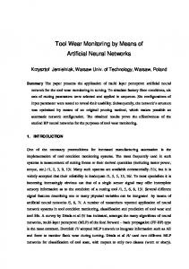
2. Proposal Proposal for system 2. fora amonitoring monitoring system model model The proposed tool monitoring system model can basically be observed through four segments united in a whole that is, using back propagation, connected with the machine-managing unit, as shown in (Fig. 1). Special segments of the system are: � sensor part � part for data acquiring, processing and analyzing � part for training neural network � part for presenting results. Sensor part of the machine tool is made of measuring bearing placed in the front bed of the machine tool main spindle. Besides the measuring bearing, there is also another sensor working on the principle of measuring strain gauge, placed on the processing tool holder and designed specially for this case for measuring cutting forces appearing on the tool itself [10, 11, 12, 13]. Part for data acquiring, processing and analyzing contains standard A/D card ED 300, which receives input data from the existing sensors, converts them to digital information, and sends them to computer database. For information flow, the composite software named ED LINK is responsible, allowing the possibility for programming conditioning speed and type of input data [10, 11]. Neural network built into the system is a multi-layer perception network with signal spreading in one direction (feedforward topology), and one of the best-known types of feed forward neural networks. The network has three layers: the input layer contains three neurons, intermediate hidden layer contains m neurons, and the output layer has one neuron. Software system is designed to acquire and process information in on-line work regime and to manage the work of hardware components, so it can be based on set limitations for monitor processing and tool wear. To establish the degree of tool wear, we can utilize comparative analysis of wear curves obtained by system training using neural networks. Determining the leftover tool duration is set on the basis of wear trend gained by comparative analysis with the wear curve and real condition.
READING DIRECT: www.journalamme.org
147
Journal of Achievements in Materials and Manufacturing Engineering
Volume 14 Issue 1-2 January-February 2006
unit value. For i-th value of the input vector from the variable registered by the measuring bearing FRprom, normalization formula can be written in the following way:
pˆ i � where
p sr �
p i � p sr . sp
1 N
(1)
N
�p. i �1
(2)
i
is an average value, and
sp �
Fig. 1. Algorithm of the developed tool monitoring system based on neural networks
3. Neural network for tool 3. Neural network forwear tool wear monitoring monitoring 3.1. Pre-processing and training 3.1. Pre-processing and training setset As already stated, neural network has three inputs to which the force values from the sensor on the tool holder, measured force from measuring bearing, and cutting speed are directed. Using these three values, the neural network at its output evaluates the values of flank wear VB in the same time moment. For the need of training process, a set was formed containing 30,900 input vectors and the same number of precise values of output variable. In creating the set, special attention was given to data representatives, that is, data was selected to cover all the interval of possible values of input variables and to be adequate to real change conditions. The training set formed in such a manner ensured that neural network correctly approximated the dependence of input values and output variable on the whole range of input sizes. In order to have efficient training, all the values in the training set were previously normalized. Normalization was performed in a way that every input and output size in the training set had the average value equal to zero, and standard deviation reduced to
148
Research paper
1 N ( p i � p sr ) 2 � N � 1 i �1
(3)
is a standard deviation of the process variable input vector defined over the whole training set (N = 30,900). The formulas for other variables in the training set can be written similarly. Before the training process, apart from data normalization, it was necessary to perform the selection of neural network topology. Since the values of the output variable VB depended solely on momentary values of input variables, a multi-layer perception network with signal spreading in one direction (feedforward topology) was selected for network topology. In addition, the theory stated that the function that the resultant neural network had to approximate was distinctly non-linear; hence, for the output function of neurons in the hidden layer a sigmoid function was selected [14, 15]:
y (net i ) �
2 � 1. 1 � e � neti
(4)
where M
net i � � w ji x j � bi ,
(5)
j �1
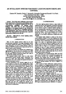
is the sum of input network sizes multiplied with appropriate neuron weight coefficients. The network used, as already said, had three layers: input, hidden and output, as shown in (Fig. 2); it presented a sufficient number of layers for the problem under observation, considering the fact that multi-layer perception with one hidden layer could with arbitrary accuracy � � 0 uniformly approximate any real continual function on the real final axis.
Fig. 2. Neural network topology
A. Antić, J. Hodolič, M. Soković
Manufacturing and processing
In the input as well as the output layer, the number of neurons was determined by the number of inputs, and outputs, so that input layer contained three neurons that corresponded to input variables (FRtool, FRprom, Vm/min), and the output layer contained one neuron whose output gave the value of the estimated size of flank wear VB. The number of neurons in the hidden layer was determined by experiments comparing network performances with different number of neurons in the hidden layer. During the experiment, networks were tested with two to seven neurons in the hidden layer, and for every topology several trainings with the same training set were performed so that the performances of every topology could be estimated as objectively as possible. Networks with a small number of neurons (two and three neurons) in the hidden layer did not present satisfactory results, which can be attributed to insufficiently rich network structure that implied small capacity for function approximation. Networks with five or more neurons in the hidden layer successfully approximated input-output dependence, so any of those topologies was adequate for implementation. In selecting final topology, a general direction was used saying that the total number of neurons in a neural network should be as small as possible, since in that way the generalization network abilities were increasing and the appearance of ”over fitting” was avoided. Considering all mentioned a network with five neurons in the hidden layer was selected for the final network structure.
Neural network final topology was trained several times with the same training set, yet each time with the new, randomly generated, initial values of weight coefficients (Fig. 3). For the maximal value of iterations, the value 1,000 was adopted, since it was noticed that in the later iterations the neural network error was not reduced by any significant value. Neural network training finished with the intermediate square error (calculated over the entire training set) in the interval between 10-3 and 10-4. This error was calculated with the normalized data; so, to get real value of intermediate square error it was necessary to multiply the gained value with the value of standard deviation of flank wear VB. On our training set, the standard deviation of flank wear had the value 0.0013, so the real value of intermediate square error was between 10-6 and 10-7.
4. Experiment setup 4. Experiment setup Machine parameters were selected in order to respond to industrial application in real manufacturing. Machine conditions for every experiment are presented in Table 1. The experiments were repeated under the same conditions for the possibilities of training, verifying and testing neural network model. Basically, cutting speed and training number varied. There were ten experiments in total, all of them with the same basic configuration. However, some of the experimental conditions were being changed to isolate disturbances and identify the properties of adequate monitoring signal. Special focus was on ensuring that all experimental conditions remained the same, except for the parameters that were changed under control. The basic configuration of the experimental measuring setup is shown in (Fig. 4), and it contains CNC lathe equipped with sensors for measuring cutting force, those being: promess sensor and specially designed sensor with measuring strain gauge placed on the tool holder.
Fig. 3. The change of intermediate square error during neural network training Training ANN was performed with “resilient” modification of the basic back propagation algorithm that was designed for ANN with “squashing” activation functions, that is, functions that compress the infinite input area into the final output interval (like sigmoid function). These functions could cause problem while using basic back propagation algorithm, since the gradient could have very small values and therefore cause small changes in weight coefficients, which led to long-term training. Thus, the “resilient” algorithm utilized only the sign of partial inference in order to determine the direction of weight coefficient changes, while the change size was determined by a special parameter whose value was, during the training, changed following the special algorithm.
Fig. 4. Basic configuration of the experimental measuring setup
Development of an intelligent system for tool wear monitoring applying neural networks
149
Journal of Achievements in Materials and Manufacturing Engineering
Table 1. Experiment parameters Machine Holder Insert Cutting depth [mm] Speed [m/min] Material workpiece Number of passing Total time [min] Diameter [mm] Passing length [mm]
Exp. 1
110 36 60 10
Exp. 2 ... Exp. 10 INDEX GU 600 PTGNL 25x25 TNMG 220408 1 mm 200 �.4730 132 ... 112 43 ... 37 60 ... 60 10 ... 15
Volume 14 Issue 1-2 January-February 2006
300 �m a)
300 �m b)
5. Results 5. Results The selected appropriate model was established to be relatively reliable method for monitoring tool wear during hard turning. During the research, several different network configurations were used and studied for their application in tool wear monitoring during hard turning. It is known that static cutting forces are good tool wear indicators; however, adequate dynamic analysis of cutting forces can also give satisfactory properties for wear monitoring. (Fig. 5) presents cutting force components measured during tool wear monitoring.
300 �m c)
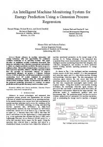
Fig. 6. Tool insert for experimental measurements
40 35
F(x,z) force
30 25 20 15 10 5 0
time s
Fig. 7. Neural network exact value and estimated value
Fig. 5. Cutting forces measured during monitoring Tool wear (VB) was measured after each turning and the value suiting one passing was linearly put into the table. Wear measuring was performed using tool microscope having the 30 times enlargement. Inserts used in the experiments were coated by TiN. Their life expectancy had the tendency to terminate suddenly after the coating disappeared from the cutting part, which could be seen in swift and sudden jump of cutting force. Fig. 6 shows the appearance of worn inserts during the experiment, a) tool insert from experiment 1, b) tool insert from experiment 3, c) tool insert from experiment 5. Fig. 7 presents the agreement between the model of the estimated value of the trained neural network and the exact value gained by measuring. For better survey, Fig. 8 presents normalized intermediate value of the estimated value gained results and measured results. Wear measuring results used for training were given in Fig. 9 for experiments 1-5. In each case, the model was tested on the previously unseen data since these parameters remained constant during every individual test of tool life expectancy.
150
Research paper
Fig. 8. Normalized intermediate value of real measuring and estimated values
A. Antić, J. Hodolič, M. Soković
VB [mm]
Manufacturing and processing
measured values
measured values
measured values
measured values
measured values
model estimated values
network layers and neurons. The model was set so it could be upgraded rather easy by dynamic neural network, which is one of relatively new research directions in this field.
0.16 0.14 0.12 0.1 0.08 0.06 0.04 0.02 0
References References [1] [2]
0
1
2
3
4
5
6
time [min]
7
8
9
10
11
Fig. 9. Real measuring results Table 2. Parameters of input sizes and standard deviation Intermediate value of Intermediate value of input sizes output size 481.2658 0.0034 964.7022 264.3197 Standard deviation of Standard deviation of input sizes output size 346.0206 0.0013 453.1569 39.2540 Table 2 presents intermediate value parameters of input sizes and with standard deviation.
[3]
[4]
[5]
[6]
[7]
[8]
6. Future work 6. Future work The lack of neural networks (same as many other experimental models) requires long-term training with data normalization with the values expected to be working in the real conditions. The network cannot work without previous training. To expand one’s work, it is necessary to utilize both numerical and experimental methods. Considering the fact that the network should be re-trained from time to time, training period can be considered as a major drawback in the application of neural networks in real manufacturing. However, future research could include the integration of the existing system into CNC-machine, instead of currently separated device; this would ensure that monitoring system and machine could react synchronically, i.e. the machine could react by stopping once the over-worn tool is detected. More precisely, dynamic neural networks to ensure additional correction of the trained static network in on-line work regime could also enlarge the existing model.
[9] [10]
[11] [12]
[13]
7. Conclusions 7. Conclusions The paper presented that neural networks (NN) can be used for efficient wear monitoring during hard turning, with the listed limitations. After considering many possible setups for wear monitoring model using different configuration types of neural networks, and based on input and output parameters, the one selected performed with optimal results for the selected number of
[14] [15]
C. Scheffer, H. Kratz, P.S. Heyns, F. Klocke: Development of a tool wear-monitoring system for hard turning, International Journal of Machine Tools & Manufacture 43, (2003), 973–985. M. Balazinski, E. Czogala, K. Jemielniak, J. Leski: Tool condition monitoring using artificial intelligence methods, Engineering Applications of Artificial Intelligence 15, (2002), 73–80. B. Siek: On-line indirect tool wear monitoring in turning with artificial neural networks, a review of more than a decade of research, Mechanical Systems and Signal Processing 16(4), (2002), 487–546. D.E. Dimla Sr., P.M. Lister: On-line metal cutting tool condition monitoring. II: tool-state classification using multilayer perception neural networks, International Journal of Machine Tools & Manufacture 40, (2000), 769–781. Shang-Liang Chen, Y.W. Jen: Data fusion neural network for tool condition monitoring in CNC milling machining, International Journal of Machine Tools & Manufacture 40, (2000), 381–400. U. Zuperl, F. Cus, M. Milfelner: Fuzzy control strategy for adaptive force control in end milling, COMENT Worldwide Congress on Materials and Manufacturing Engineering and Technology, Glivice-Wisla, Poland, 2005, pp3.399. T. Ozel, A. Nadgir, Prediction of flank wear by using back propagation neural network modelling when cutting hardened H-13 steel with chamfered and honed CBN tools, International Journal of Machine Tools & Manufacture 42, (2002), 287–297. R. Kothamasu, S.H. Huang, Intelligent tool wear estimation for hard turning: Neural-Fuzzy modelling and model evaluation, Proceedings of the Third International Conference on Intelligent Computation in Manufacturing Engineering, Ischia, Italy, 2002, 343–346. C. Scheffer, P.S. Heyns: An industrial tool wear monitoring system for interrupted turning, Mechanical Systems and Signal Processing 18 (2004), 1219–1242. A. Antic, J. Hodolic, R. Gatalo, M. Stevic, Contribution to the development of the multi-sensor system for tool monitoring, Annals of DAAAM & Proceedings of the 12th international DAAAM Symposium, Vienna, Austria, 2001, 009-010. A. Antic: A Contribution to the development of tool monitoring system in flexible manufacturing systems, Master’s thesis, Faculty of Technical Sciences, 2002. F. Cus, M. Milfelner, J. Balic An overview of data acquisition system for cutting force measuring and optimization in milling Contemporary, COMENT Worldwide Congress on Materials and Manufacturing Engineering and Technology, GliviceWisla, Poland, 2005, pp 1.368. J.S. Son, D.M. Lee, I.S. Kim, S.G. Choi: A Study on On-line learning Neural Network for Prediction for Rolling Force in Hot-rolling Mill, COMENT Worldwide Congress on Materials and Manufacturing Engineering and Technology, GliviceWisla, Poland, 2005, pp 3.355. P. D. Lippman, "Neural Computing – theory and practice", Van Nostrand Reinhold N. Y., 1989. M. Riedmiller, and H. Braun, A direct adaptive method for faster back-propagation learning: The RPROP algorithm, Proceedings of the IEEE International Conference on Neural Networks, 1993.
Development of an intelligent system for tool wear monitoring applying neural networks
151