of automated dedicated fixture configuration design is studied with predefined fixture component .... resistance to wear, and shorten the manufacturing lead-time.
DEVELOPMENT OF AUTOMATED DEDICATED FIXTURE CONFIGURATION DESIGN SYSTEMS WITH PREDEFINED FIXTURE COMPONENT TYPES: PART 1, BASIC DESIGN Z. An, S. Huang and Y. Rong Manufacturing Engineering Program, Department of Mechanical Engineering Worcester Polytechnic Institute, Worcester, MA 01609-2280 S. Jayaram Manufacturing and Logistics Technology Technical Center, Caterpillar Inc., Peoria, IL 61656-1875
ABSTRACT: An automated modular fixture design system has been developed in our previous study. Since dedicated fixtures are commonly used in mass production, in this research, a technique of automated dedicated fixture configuration design is studied with predefined fixture component types. The design methodology is divided into two stages: basic design and detail design. The basic design activities include 1) selection of functional fixture components such as locators and clamps from a standard fixture component database, 2) generation of customized supports with variable dimensions for different fixture design requirements, and 3) assembly of fixture components into a final configuration on a fixture base. In order to implement the fixture design procedure, models are developed to represent the standard fixture components and customized supports. The assembly relationships among fixture components are established based on a compatibility analysis. The detail design includes fixture unit combination, connection design, interference avoidance modification, and technological-rule-based modification. In this paper, the principles and implementation of basic design are presented, while the detail design will be addressed in a separate paper.
INTRODUCTION Fixtures are used to locate and hold workpieces during the manufacturing processes to ensure production quality, productivity, and low-cost. Fixtures can be generally divided into two categories: modular fixtures and dedicated fixtures [1]. Modular fixtures are composed of standard fixture components such as standard locators, clamps, supports and baseplates that can be assembled into a variety of configurations for different workpieces and used in low-volume production applications [2]. Dedicated fixtures are specially designed and fabricated for a given workpiece and are used in mass production due to the advantages of specially designed performance, such as convenient operation, stiff support in desired directions, and efficient structural space utilization. Since fixture design and fabrication contributes significantly to the manufacturing quality and lead time, it is desired to automatically design and verify dedicated fixture designs in the product design and manufacturing planning stage so that alternative designs can be compared for optimal solutions. In addition, an automated fixture design process is desired to accommodate flexible manufacturing systems (FMS) and computer-integrated manufacturing systems (CIMS) [3]. Fixture design can be divided into three phases: setup planning, fixture planning, and fixture configuration design. The objective of setup planning is to determine the number of setups, the position and orientation of workpiece in each setup, and machining surfaces in each setup [4]. Fixture planning is to determine the locating, supporting, and clamping points on workpiece surfaces [5]. The task of fixture configuration design is to select or generate fixture components and place them into a final configuration to fulfill the functions of locating and clamping the workpiece [6].
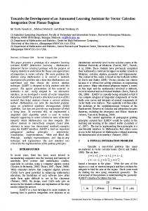
This research is concentrated on fixture configuration design. The inputs to the automated dedicated fixture configuration system are the fixture planning for a certain setup, the CAD model of the workpiece, and CAD models of the fixture components. The output of the system is a dedicated fixture configuration design. Previous research on automated fixture design concentrated on modular fixtures. The related studies includes: automated modular fixture configuration design with the assistance of fixture component assembly relationship [6, 7]; fixture design retrieval based on group technology [8, 9] and casebased reasoning [10, 11] techniques; fixture design based on kinematics analysis [12-14], expert systems [15-17], and geometric analysis [18,19]; fixturability [20] and fixturing surface accessibility analysis [21]; and a preliminary work on automated generation of dedicated fixture designs [22]. There are certain key differences between dedicated and modular fixtures. In modular fixture design, there is a component library with pre-designed and dimensioned standard fixture components. Thus, the modular fixture configuration design is actually to assembly the fixture components into a configuration. In designing dedicated fixtures, the fixture components can be designed from geometric shapes with variable dimensions and connections. There are more uncertainties imposed on dedicated fixture design tasks. To streamline the whole design process, automated dedicated fixture configuration design is divided into two stages: basic design and detail design, as shown in Figure 1. The basic design mainly concerns the generation of an initial result of the dedicated fixture configuration, including the standard fixture component selection, support type selection and dimensioning, and the position and orientation determination of the fixture components. The detail design includes fixture unit combination, interference avoidance modification, connection design, and technological-rule-based modification. The fixture unit combination is to optimize the fixture structure by combining two or more functional units into a multi-purpose unit based on functional and spatial conditions. The interference avoidance modification is to check the interference that may exist in the design result and then make proper modifications. The connection design is to finalize the connection features between fixture supports and the fixture base, and between standard locator/clamp and supports. Stage 1 --- basic Workpiece model & machining Standardized customize fixture componen library
Fixture componen model database
Workpiece placement in fixture Fixturing surface/point selection on Generation of functional 1. Selection of standardized detailed type and 2. Generation of customized 3. Placement of result fixture components fixture workspace by fixture base generation &
Fixture componen relationshi
Stage 2 --- detail design Unit combination Interference avoiding Technological-rule-based
Rule
Connection design between fixture (like welding, screwing, and
Figure 1. Automated dedicated fixture configuration design process
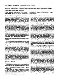
Based on a structural analysis of dedicated fixtures, techniques to implement the automated dedicated fixture configuration design have been developed. A prototype system has been implemented on a commercial CAD platform. This paper presents the structural analysis of dedicated fixtures first, and then address the techniques related to the basic design. Detail design, however, will be presented in a separate paper [23]. STRUCTURAL ANALYSIS OF DEDICATED FIXTURES Generally, a dedicated fixture is made up of several functional units on a fixture base to fulfill certain fixturing functions including locating and clamping. Typical fixturing functions are illustrated in Figure 2. A functional unit usually consists of locators/clamps and a support. In principle, all the fixture components of dedicated fixtures can be customized. However, locators/clamps are typically standard components as they come in direct contact with the workpiece and are easily worn out. The standard components also permit exchangeability, ensure high resistance to wear, and shorten the manufacturing lead-time. On the other hand, supports are used to support locators/clamps on the fixture base. They are usually customized in shape and dimensions to satisfy the different requirements of the workpiece and fixture configurations. Therefore, the design of supports needs to be generated for adapting different application situations. workpiece
workpiece
support
locator support
locator base
base
(a). Bottom-locating
(b). Side-locating clamp
clamp
workpiece
workpiece Spring
support
support base
base
(c). Side-clamping
(d). Top-clamping Figure 2. Typical fixturing functions
It is also a fact that in many cases, the types of supports are predefined based on existing practice and experiences. In order to design and fabricate fixture supports quickly, the basic shape templates of the supports are pre-defined while the detailed shape, dimensions and assembly positions are changeable in different fixture designs. Therefore, the major tasks of an automated dedicated fixture configuration design in this research are to select the appropriate fixture component types, determine dimensions, and place them into a configuration on the fixture base. BASIC DESIGN OF DEDICATED FIXTURES Based on the structural analysis of dedicated fixtures, the following five representations and models are established to support the automated dedicated fixture configuration design: • Fixturing Requirement Representation is defined to identify fixture design input information; • Standard Fixture Component Model is established for the type and dimension selection of locators/clamps;
• • •
Customized Support Template Model is established for the generation of supports; Fixture Component Relationship Database is established for determining the compatibility between locators/clamps and basic support templates; Constraint-based Fixture Component Assembly Model is established for positioning fixture components on fixture base.
In the following subsections, these representation and models are introduced as the foundation for the automated dedicated fixture configuration design system. Fixturing Requirement Representation Fixturing requirements are identified in the fixture planning stage, where the fixturing accuracy, accessibility, and stability are considered in determine the fixturing surfaces and points [5]. The results of fixturing requirement identification include the fixturing positions, the number and the types of fixture units required, and the properties of the fixturing surfaces and points. A functional fixture unit is originated from the specified fixturing surface/point on the workpiece. Thus, the representation of the fixturing surface/point should provide the information for the generation of the fixture units. Fixturing requirement representation can be defined by a set of geometric and machining data as follows: v M FS _ WP = { Fid , Fgeo_type , Ffunc_type , Ffinish , FDOF , n, p1, p2, S accs , Paccs , Stiff } where: Fid is an integer number representing the fixturing surface ID; Fgeo_type is the geometric type of the fixturing surface which could be a plane, inner or outer cylindrical surface; Ffunc_type is a fixturing function type of the fixturing surface, which could be side-locating, side-clamping, bottomlocating, or top-clamping; Ffinish is the surface finish of the fixturing surface; FDOF is the number of v degrees of freedom to be restricted; n is a normal vector of the fixturing surface if the Fgeo_type is a plane, or the axis vector if Fgeo_type is a cylindrical surface; p1 is the primary fixturing point; p2 is the optional assistant point which may be needed to determine the orientation of the locator/clamp; S accs is the surface accessibility value; Paccs is the value of local fixturing point accessibility; and Stiff is the stiffness requirement for the fixture unit. Among all the model items, Ffunc_type, Ffinish, FDOF, and Stiff are user-specified, S accs and Paccs can be obtained by using the discretization algorithm [21], and others can be directly extracted from the workpiece CAD model when the fixturing surface/point is specified. Standard Fixture Component Model In dedicated fixture design, one important issue is to use standard fixture components as much as possible for the purpose of reducing fixture fabrication time and cost. Since the functional fixture components (locators/clamps) are in direct contact with workpieces and subject to wear, it is desired that these components are made of hard materials and replaceable. Therefore the locators/clamps are usually standard and commercially available in certain dimension series. A standard fixture component model is established for selecting and dimensioning standard fixture components in dedicated fixture design, which leads to the establishment of standard fixture component database. A standard fixture component can be described with its component type, functional surfaces, and dimensions. The information is retrieved during standard fixture component selection. Figure 3 shows some examples of standard locators and clamps. The fixture component type information is used to determine how the component is used in fixture design. The functional surfaces used to locate or clamp the workpiece are defined as contact faces and the associated functional points are defined as contact points. The surfaces in contact with the fixturing supports are defined as supported faces and the associated points are defined as the supported points. For example, in Figure 4(a), the highlighted top surface is the contact face and its center point PNT1
is the contact point, while the highlighted surface in Figure 4(b) is the supported face and its center point PNT2 is the supported point. The functional surface can be represented as follows: v Func_Surf = {Surface_Id, Surface_Type, n , Point_Id, Point_Type, If_ct_above_spted, Surface_Prop} where: Surface_Id is an integer number representing the functional surface ID; Surface_Type is the v functional type of the functional surface which could be “contact” or “supported”; n is the normal direction of the functional surface; Point_Id is an integer number representing the functional point ID; Point_Type is the type of the functional point which could be on plane, on cylinder, on sphere, on cylinder axis, on hole axis, or on slot; If_ct_above_spted describes the relative positional relationship between the contact surface and the supported surface which could be +1 or -1; Surface_Prop is the surface finish of locating surface.
a). Radial rest button
f). V_block
b). Flat rest button c). Rectangle rest pad
(g). Screw clamp
d). Round locating pin
e). Diamond locating pin
(h). Strap clamp
(i). Hook clamp
Figure 3. Examples of standardized locators/clamps with detailed types
(a) CONTACT_FACE/PNT
(b) SUPPORTED_FACE/PNT
Figure 4. Functional surfaces/points of a flat rest button The dimensional information is an important part of the standard fixture component model. For a particular component, primary design dimensions play a major role in determining how a component fits the workpiece. The primary design dimensions may determine the primary size, functional height, and primary connection size of a standard fixture component. For example, the diameter of the rest button (φdia_a) in Figure 5 and the linear dimension of the rest pad (oal_b) in Figure 6 are such primary design dimensions. The dimensions of thk_b in Figure 5 and pad_thk in Figure 6 are functional height dimensions. And φdia_d in Figure 5 and φdia_c in Figure 6 are primary connection dimension. The locators/clamps are selected according to their primary dimensions. Other dimensions may be defined with certain relationships with the primary design dimensions. Typically, the locators/clamps of the standard component library are composed of families of components (also called “table-driven” components or instances). A family of components is a collection of similar components varying in different sizes or slightly different detailed features. Every family has a generic basic model that all instances of the family resemble. Concepts like class, inheritance, and group technology can be applied here for an effective way of retrieving large
number of standard components. Figure 5 shows an example of generic model with dimension names displayed and its instances are listed in the form of family table as shown in Table 1. TATBLE 1 Example of Family Table
Figure 5. Generic model of a rest button
instance
dia_a
thk_b
oal_c
dia_d
4_41475
9.7
4.78
12.7
6.375
4_45065
10
6
12
6.025
4_45066
10
8
14
6.025
4_45067
13
6
14
8.025
4_45068
13
8
16
8.025
4_45455
13
7
20
10
4_45060
19
10
25
12.025
4_45061
19
12
28
12.025
Thus each dimension can be described as follows: DIMENSION = {dim_name, dim_type, func_type, famtab_attribute, default_value, min_value, max_value} where: Dim_type is the dimension type and could be a diameter, radius, length, or angle; Func_type could be a primary design dimension, functional height, supported connection dimension, or contact height; and Famtab_attribute Indicates if the dimension is obtained from a family table or not which could be 1 or 0. Customized Support Template Model In fixture design, the function of supports is to connect the locators/clamps to the fixture base and to make the height of the fixture unit. Although the support may vary greatly in shape and size due to the diversity of workpiece and different fixturing requirements, in many cases, the basic shapes of the supports are usually pre-defined in shop practice and stored in a computer database. Typical support shapes are shown in Figure 7 where the dimensional relationships are different for different types of supports. Detailed shapes, dimensions and assembly positions of the supports may be changed for different fixture designs. Therefore, several basic support templates are employed as the basis for obtaining a suitable support components through the modification of shape and dimensions.
Figure 6. Generic model of a rest pad
(a) side locating/clamping (b) top clamping support (c) bottom locating support support template template template
Note: The dimensional relations of these support templates are different. Figure 7. Typical support templates Similarly to the standard fixture component, each support template can be modeled with its type, functional surfaces, and dimensions. The functional surfaces used to support the locator/clamp are defined as supporting faces and the associated functional points are defined as supporting points. The surfaces used to connect the support to the fixture base are defined as supported faces and the associated functional points are defined as supported points. Figure 8 shows an example case of bottom locating support where the top surface as the supporting faces and PNT0 are the supporting points, while the bottom surfaces are the supported faces and the centers PNT1 are the supported points. Thus, the functional surface of support template can be modeled as follows:
v
Func_Surf={Surface_Id, Surface_Type, n , Point_Id, Point_Type} Dimensional information is also important in the support template model. Unlike the standard fixture component, most of the dimensions are relation-driven. The primary design dimension of a support template is the dimension that represents its functional height. The functional height satisfaction is at the top priority among the design rules. When the value of functional height dimension changes to fit the clearance between the locator/clamp and the fixture base, other dimensions need to be changed accordingly. The changes of other dimensions can be realized either by recommended relations with the primary design dimensions or by user specification. Some dimensions are constant when the primary dimension is in a certain range. For example, among all the dimensions of the support template as shown in Figure 9, d4 represents the functional height and hence is the primary design dimension. Other dimensions may vary according to the recommended relations. Primary design dimension: d4 Recommended dimension relations: 1) d0 = ceil (4/100)*15 2) d1 = ceil (1.3*d4) 3) d2 = ceil (d4/100)*60 4) d3 = 0.5* d2 5) d5 = d3 6) d6 = 0.5*d0 Note: ceil is a function to obtain the smallest integer not less than the real value.
SUPPORTING_FACE/PN T
SUPPORTED_FACE/P
Figure 8. Supporting and supported faces and points of a bottom locating support
Figure 9. Example of a support template with recommended dimension relations
Therefore, for each dimension of the support template, it can be modeled as follows: DIMENSION = {dim_name, dim_type, func_type, attribute, default_value, min_value, max_value} where func_type specifies the function of the dimension, which could be the functional height, supporting connection dimension, or supported connection dimension; and attribute indicates whether the dimension is generated by relations or not. Fixture Component Relationship Database The fixture component relationship provides the information for determining if a particular support can be used with a selected locator/clamp. The fixture component relationship database can be described in a decision matrix. The rows of the table index the detailed types of the standardized locators/clamps, while the columns index the detailed types of the customized support templates. The element at position (i, j) represents whether jth locator/clamp can be supported by ith support. The fixture component relationship database can be constructed either interactively or automatically. In the interactive mode, an operator decides what kinds of locators/clamps can be used with what kinds of support templates and the corresponding values in the table. On the automated method, feature recognition and relationship inference techniques are used to determine the database, as illustrated in Figure 10. To construct the fixture component relationship database through feature recognition and relationship inference, the functional type (such as bottom locating or side clamping) and geometric match conditions (such as component size and contact area) between locators/clamps and supports are considered. Constraint-based Fixture Component Assembly Model The constraint-based fixture component assembly has been applied to modular fixture design [24] and can be also applied to the dedicated fixture design. To assemble components properly, three
rules are applied: 1) The constraints must be complete; 2) The component cannot be over constrained; 3) The dependence on other components should be reduced as much as possible.
Standard Component Database Relationship Inference Engine Support Template Database
Fixture Component Relationship Database
Figure 10. Automatic construction of fixture component relationship database In order to specify the spatial constraints between the locators/clamps and the workpiece, a fixture workspace is defined which provides a global datum for fixture assembling. Based on the fixture workspace, four relationships are defined for the constraint-based fixture component assembly. They are, 1) the relationship between workpiece and fixture workspace; 2) the relationship between locator/clamp and fixture workspace; 3) the relationship between support and fixture workspace; and 4) the relationship between fixture base and fixture workspace. First, to assemble the workpiece into the fixture workspace, a coordinate system is defined on the workpiece model to position and orient the workpiece with respect to the z-axis of the machining tool axis. To position locator/clamp in the fixture workspace, the constraint relationships are specified between the locator/clamp and the fixture workspace. A complete functional fixture unit in the fixture workspace is composed of a locator/clamp and a support. After the locator/clamp has been positioned according to the constraint-based relationship between the locator/clamp and fixture workspace, the corresponding support needs to be assembled by the constraint-based relationship between the support and fixture workspace as shown in Figure 11 and 12. Finally, the fixture base is placed into the fixture workspace by following the same principles as assembling the workpiece, i.e., the alignment constraint of the datum coordinate systems is kept the same between the fixture base and the fixture workspace. The size of the fixture base is determined in terms of the overall dimensions of the workpiece and fixture units after they are assembled together. It is noted that all the assembly functions are implemented automatically by the fixture design program. fixture SUPPORTED_P on DATUM_PLA parallel SUPPORTED_FA on
customized Alig Orient
workpiece
SUPPORTING_P SUPPORTING_F
Orient ADTM
SUPPORTED_FA ADTM3
Figure 11. Constraint model of assembling customized support
Figure 12. Example of assembling a rest button
IMPLEMENTATION OF DEDICATED FIXTURE CONFIGURATION DESIGN SYSTEM
Based on the fixture workspace relationships defined above, an automatic generation of dedicated fixture configuration design is implemented. The procedure of generating a fixture unit is as following. 1) to generate a fixture workspace; 2) to position the workpiece in the fixture workspace according to the constraint-based assembly relationship; 3) to select the type and dimensions of locator/clamp, and to assemble it into the fixture workspace according to the constraint-based assembly relationship; 4) to select the support template according to the fixture component relationship, determine dimensions of the support by matching the primary design dimension with functional requirement such as the supporting height, and then mount it into the fixture workspace according to the constraint-based assembly relationship; and 5) to select or generate a fixture base and assemble it into the fixture workspace according to the constraint-based assembly relationship. In selecting the type of a locator/clamp, a rule base needs to be established in advance. Then, an instance with proper dimensions needs to be determined based on the dimensional information of the workpiece. The type of support template is determined according to the fixture component relationship pre-stored in a database. To dimension the support, the primary design dimension is determined such that the functional height of the selected locator/clamp instance is reached with respect to the fixture base. Other dimensions of the support template can be adjusted by recommended relations accordingly. After the dimension adjustment, the required support model can be obtained by regenerating the corresponding support template based on the parametric CAD modeling technique. A prototype of basic design module of the automated dedicated fixture configuration design system has been developed on a commercial CAD platform by incorporating C++ with an application programming interface (API). The system consists of four basic modules: 1) component info input; 2) automated design; 3) design modification; and 4) design output. Figure 13 shows a fixture design example designed by using this prototype system.
( a ) Design result ( b ) Component layout Figure 13. Example of dedicated fixture configuration design SUMMARY An automated dedicated fixture configuration design system has been developed for industrial applications. Based on the dedicated fixture structure analysis, the design process is divided into two stages: basic design and detail design. In basic design, according to the fixture design requirements, standard locators/clamps are automated selected with type and dimensions, customized supports are generated based on a selection of predefined support templates and a dimension adjustment from the build-in relationships in the support models, and finally all the fixture components are assembled onto a fixture base in terms of specified assembly constraints. A design example is presented. The detail design will be presented in a separate paper.
REFERENCES
1. E. G. Hoffman, Jig and Fixture Design, 3rd ed., Delmar, New York, 1991. 2. Y. Rong and Y. Zhu, Computer-aided Fixture Design, Dekker, New York, 1999. 3. Thompson, B. S. and M. V. Gandhi, Commentary on Flexible Fixturing, Applied Mechanics Review, Vol. 39, No 9, 1986, pp. 1365-1369. 4. Y. Rong, X. Liu, J. Zhou and A. Wen, Computer-aided setup planning and fixture design, Int. J. of Intelligent Automation and Soft Computing, Vol. 3, No. 3, 1997, pp. 191-206. 5. W. Ma, J. Li and Y. Rong, Development of automated fixture planning systems, Int. J. of Advanced Manufacturing Technology, 1999, 15:171-181. 6. Y. Rong and Y. Bai, Automated Generation of Modular Fixture Configuration Design, Journal of Manufacturing Science and Engineering, Vol. 119, May 1997, pp. 208-219. 7. Y. Rong and Y. Bai, Modular Fixture Element Modeling and Assembly Relationship Analysis for Automated Fixture Configuration Design, Journal of Engineering Design and Automation, Vo.4, No.2, 1998, pp. 147-162. 8. P. M. Grippo, M. V. Gandi, and B. S. Thompson, The Computer-aided Design of Modular Fixturing Systems, International Journal of Advanced Manufacturing Technology., 1987, Vol.2, No.2, pp. 75-88. 9. Y. Zhu and Y. Rong, A computer-aided fixture design system for modular fixture assembly, Quality Assurance through Integration of Manufacturing Processes and Systems, ASME WAM, Anaheim, CA, Nov. 8-13, 1992, PED-Vol. 56, pp. 165-174. 10. A. S. Kumar and A. Y. C. Nee, A Framework for a Variant Fixture Design System Using Casebased Reasoning Technique, Computer-aided Tooling, ASME WAM, 1995, MED-Vol. 2-1, pp. 763-775. 11. S. H. Sun, and J. L. Chen, Knowledge Representation and Reasoning Methodology Based on CBR Algorithm for Modular Fixture Design, International Journal of Advanced Manufacturing Technology, January 1996. 12. Y. C. Chou, V. Chandru and M. M. Barash, A Mathematical Approach to Automatic Configuration of Machining Fixtures: Analysis and Synthesis, Journal of Engineering for Industry, 1989, Vol.111, pp.299-306. 13. H. Asada and A. B. By, Kinematic Analysis of Workpart Fixturing for Flexible Assembly with Automatically Reconfigurable Fixtures, IEEE Journal of Robotics and Automation, Vol. RA-1, No. 2, 1985, pp. 86-94. 14. M. Mani, and W.R.D. Wilson, Automated Design of Workholding Fixture Using Kinematic Constraint Synthesis, 16th NAMRC, Urbana-Champaign, IL, May 1988, pp.437-444. 15. A. Y. C. Nee and A. S. Kumar, A Framework for an Object/Rule-based Automated Fixture Design System, Annual of the CIRP, 1991, pp.147-151. 16. A. Markus, E. Markusek, J. Farkas and J. Filemon, Fixture Design Using Prolog: An Expert System, Robotics and CIMS, 1984, Vol.1 No.2, pp.167-172. 17. D. T. Pham, and A. De Sam Lazaro, AUTOFIX - An Expert CAD system for Jig and Fixtures, International Journal of Machine Tool & Manufacture, 1990, Vol. 30, No. 3, pp. 403-411. 18. K. Y. Goldberg and R. Brost, A Complete Algorithm for Synthesizing Modular Fixtures for Polygonal Parts, IEEE Transaction on Robotics & Automation, Vol. RA-12, No. 1, 1996, pp. 3146. 19. Y. Wu, Y. Rong, W. Ma and S. LeClair, Automated modular fixture design: geometric analysis, Robotics and Computer-integrated Manufacturing, 14:1-15, 1998. 20. S. K. Ong and A. Y. C. Nee, A Systematic Approach for Analyzing the Fixturability of Parts for Machining, Computer-aided Tooling, ASME WAM, 1995, pp. 747-761. 21. J. Li, W. Ma and Y. Rong, Fixturing Surface Accessibility Analysis for Automated Fixture Design, Int. J. of Production Research, 1998, Vol. 37, No. 12, pp. 1-20; 22. Y. Wu, Y. Rong and T. Chu, Automated generation of dedicated fixture configuration, Int. J. of Computer Application in Technology, Vol. 10, No. ¾, 1997, pp. 213-235.
23. Z. An, Y. Rong and S. Jayaram, Development of Automated Dedicated Fixture Configuration Design Systems with Predefined Fixture Component Types: Part 2, Detail Design, submitted to International Journal of Advanced Manufacturing Technology, 1999. 24. Y. Kang, Y. Rong, M. Sun, Constraint-based modular fixture assembly modeling and automated design, ASME IMECE, Anaheim, CA, Nov. 15-20, 1998, MED-Vol. 8, pp. 901-908.