IEEE TRANSACTIONS ON MAGNETICS, VOL. 48, NO. 2, FEBRUARY 2012
775
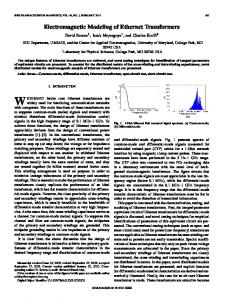
Development of Distribution Transformers Assembled of Composite Wound Cores Themistoklis D. Kefalas and Antonios G. Kladas School of Electrical and Computer Engineering, National Technical University of Athens, GR-15780 Athens, Greece
This paper proposes the manufacturing of distribution transformers using a novel type of magnetic core which is called composite wound core. A composite wound core is constructed of a combination of conventional and high magnetization grain-oriented steel. The main advantage of transformers assembled of composite wound cores over conventional transformers is the significant reduction of the manufacturing and operating cost. For the analysis of composite wound core transformers, a FE model considering anisotropy and high saturation conditions, and an advanced 3D hybrid FE-BE model have been developed. Index Terms—Finite element methods, magnetic cores, power transformers, soft magnetic materials.
I. INTRODUCTION ISTRIBUTION transformers are the second most energy intensive component of the power grid [1], [2]. According to Leonardo Energy program, losses in the electricity network worldwide are estimated at about 1 279 TWh, or 9.2% of total electricity generated [2]. One third of transmission and distribution losses take place in transformers, and two thirds in the rest of the system, while almost 70% of the losses take place in the distribution grid [2]. As a result, present energy costs are forcing transformer manufacturers and utilities to reduce transformer life-cycle costs [3]. Furthermore, a large number of researchers propose transformerless solutions for connecting renewable energy power plants to the grid on the basis of a number of arguments like reduction of losses, the cost and weight of power transformers, and the overall efficiency of the grid connected system [4]. A number of new transformer topologies, novel core joint types [5], and improved electrical steels [6], have been developed recently in order to reduce the manufacturing and operational cost of transformers. Nevertheless, there exists a technique which makes possible the improvement of transformer efficiency without the need to revolutionize the transformer topology or magnetic materials. By using, composite magnetic cores constructed with a combination of different grades of electrical steels the transformer designer can effectively reduce cost and losses [7]–[11]. This paper undertakes the development of 3-phase five-legged wound core transformers using the multiple grade lamination technique in contrast with [7]–[9] that focus on the analysis of conventional and composite wound cores and the design of the respective 1-phase core type transformer. Moreover, two advanced finite element (FE) models are developed for the accurate evaluation of the wound core distribution transformer magnetizing current, no-load loss, and short-circuit impedance during the design process. The first one considers anisotropy and high saturation conditions whereas the second one is based on a hybrid finite element-boundary element (FE-BE) formulation.
D
Manuscript received July 06, 2011; revised September 30, 2011; accepted October 15, 2011. Date of current version January 25, 2012. Corresponding author: T. D. Kefalas (e-mail:
[email protected]). Color versions of one or more of the figures in this paper are available online at http://ieeexplore.ieee.org. Digital Object Identifier 10.1109/TMAG.2011.2172976
Fig. 1. Conventional wound core transformer (a) 1-phase core type, (b) 1-phase shell type, (c) 3-phase five-legged.
II. DESCRIPTION OF WOUND CORES A. Conventional Wound Cores Typical oil-immersed, distribution transformers are constructed of one or more conventional wound cores assembled about preformed windings as shown in Fig. 1. Ratings range from a few kVA to a few MVA. Conventional wound cores, are constructed by cutting and spirally winding a flat strip of grain-oriented steel into hundreds concentric turn laminations [9]. Cutting of the electrical steel is carried out so that joints are formed in which overlap is gradual, flux transfer is eased, and flux normal to the sheet is minimized. This joint type is known as step-lap joint and its efficiency is determined by the overlap and gap lengths [1]. B. Composite Wound Cores The concept of mixed magnetic cores has been disclosed in early patents [9], and it is studied by a number of researchers [7]–[13]. The operating principle of composite wound cores is based on experimental findings concerning the local flux density distribution non-uniformity of wound cores [7], [14]. According to these findings, the flux density is low in the inner steel sheets, then it increases almost linearly up to a value higher than the core magnetization level, and finally it decreases until the outer sheets. As a result, by using conventional grain-oriented steel
0018-9464/$31.00 © 2012 IEEE
776
IEEE TRANSACTIONS ON MAGNETICS, VOL. 48, NO. 2, FEBRUARY 2012
, Fig. 3. They represent respectively, core design variables the position and amount of the high magnetization grain-oriented steel, and are subject to the constraints of (1). The design of a transformer constructed of the conventional (high magnetization) steel is a special case of the generalized design process , and and it is obtained by setting . (1)
Fig. 2. Composite wound cores comprising (a) 1-phase core type, (b) 1-phase shell type, and (c) 3-phase five-legged transformers.
B. Optimization Method The optimization methodology consists in the minimization of the total owing cost (TOC) of the transformer i.e., the sum of the first cost and the present value (PV) of its future losses, , and are the high magnetization given by (2). steel, conventional steel, and winding material unit cost ($/kg), is the mass of the winding material (kg), SM is the sales are the no-load loss and load loss (W). margin, and The and ($/W) are the PV of 1 W of no-load loss and load loss respectively, over the life of the transformer. In the case of the 3-phase five-legged transformer, the mass of the and , are high magnetization and conventional steels calculated by (3) and (4), where is the steel density (kg/m ), and is the wound core stacking factor. The minimization of (2) is subject to the three inequality conis the short straints of (5) according to IEC 60076-1, where circuit impedance (%), , and are the specified, by international technical standards, no-load loss, load loss, and short circuit impedance. TOC is also subject to the apparent power constraint, the induced voltage constraint, the temperature rise constraint and the magnetizing current constraint. The thermal calculation of the transformer is realized through the number of the windings cooling ducts, and the calculation of the cross-sectional area of the conductors is implemented from the current density. The independent variables chosen for the solution of the specific optimization problem are the design variables , the magnetization level , the number of turns of the low voltage (LV) winding , and the cross-sectional area of the LV and high voltage (HV) windings, and respectively.
Fig. 3. Design variables of a two-grade composite wound core.
(2) (3)
for the inner and outer part of the wound core, and high magnetization grain-oriented steel for the rest part of the core, transformer manufacturers may reach an optimum tradeoff between the manufacturing and the operating cost. III. DISTRIBUTION TRANSFORMERS ASSEMBLED OF COMPOSITE WOUND CORES Topologies of distribution transformers assembled of composite magnetic cores remain the same, as in Fig. 1, and the conventional wound cores are replaced by composite cores. Fig. 2 shows the parts of 1-phase and 3-phase transformers assembled of composite cores. The inner and outer part of the composite core is made of conventional grain-oriented steel and the middle part is made of high magnetization grain-oriented steel, as shown in Fig. 3. A. Generalized Design Procedure The generalized design procedure of wound core distribution transformers is obtained by considering the composite wound
(4) (5) IV. DEVELOPMENT OF 3D FE AND FE-BE TECHNIQUES A. 3D FE Formulation for No-Load Analysis For the and magnetizing currents evaluation, a 3D FE model is developed, based on a scalar potential formulation requiring no prior source field calculation. The specific formulation partitions according to (6), where is a scalar potential extended all over the solution domain and is a fictitious field distribution which is determined analytically or numerically by the conductors shape. The laminated wound core is modeled as homogeneous and anisotropic media at the level of finite elements. An elliptic
KEFALAS AND KLADAS: DEVELOPMENT OF DISTRIBUTION TRANSFORMERS
777
Fig. 5. FE-BE model of the 3-phase wound core distribution transformer.
Fig. 4. Regions comprising the FE model of a composite wound core.
anisotropy model is used due to the wound core topology. The specific model is based on the assumption that has an elliptic trajectory for the modulus of constant. The magnetic permeability is considered as a tensor quantity and the component parallel to the lamination rolling direction , is given by (7) where is the permeability component transverse to the lamination rolling direction, and is the ratio of the ellipse semi-axes. The third component , normal to the lamination plane has little influence on the 3D FE analysis and it is taken to be equal to the component along the rolling direction . Fig. 4 shows the regions comprising the FE model of a composite wound core. For regions A1 to A5, and A11 to A15, the conventional grain-oriented steel is assigned, and for regions A6 to A10 the high magnetization grain-oriented steel is assigned. Due to the wound core geometry the permeability tensor must be rotated to a different coordinate system in some of the regions of the 3D FE model. All iron loss components, including anomalous losses, are represented by the experimentally determined local specific iron loss characteristic, expressed as a function of the peak flux density and approximated by cubic splines. Wound core transformer no-load loss is evaluated by a post-processing algorithm that combines the experimentally determined specific iron losses with the FE calculated peak flux density distribution.
The evaluation of the short-circuit impedance using conventional FE techniques requires a dense discretization of the air surrounding the transformer active part. We have addressed this problem by developing a hybrid FE-BE technique. The 3D model shown in Fig. 5, is partitioned in two subdomains, the FE subdomain of the transformer active part represented by a tetrahedral mesh, and the BE subdomain between the active part and the transformer tank walls, represented by a triangular mesh of its boundaries. The solution domain was reduced to one eighth of the transformer active part. The symmetries of the problem were taken into consideration by imposing a Dirichlet at the bottom facet of the model boundary condition at the back and a Neumann boundary condition and left facets of the model as shown in Fig. 5. The boundary integral equation corresponding to Laplace equation is given by (8) where is the observation point, is the boundary coordinate, is the unit normal, and is the fundamental solution of Laplace equation in free space. The use of the hybrid FE-BE technique results in the accurate evaluation of the magnetic field in the transformer active part and in the air region, with low computational effort comparing with the FE method.
(8)
(6) (7)
B. FE-BE Computational Tool The hybrid FE-BE method has been developed in order to solve a combination of open boundary, nonlinearity, and skin effect problems. An issue remained the computational cost of the hybrid FE-BE large scale analysis. Recently, researchers have addressed this problem by combining the hybrid FE-BE technique with the fast multiple method and the minor iterative preconditioning technique [15]. So far the hybrid FE-BE method has been applied in a large number of electromagnetic analysis problems. Applications include calculation of 3D eddy currents and forces as well as analysis and design of power transformers, asynchronous motors, axisymmetric induction devices, and actuators.
V. 3-PHASE TRANSFORMER CASE STUDY The proposed optimization procedure of Section III.B was applied to a 3-phase five-legged distribution transformer, Table I. The current density chosen for the LV and HV winding were 3.2 A/mm and 3.7 A/mm . Two stochastic algorithms were used for the minimization of (2), the genetic algorithm (GA) and the simulated annealing (SA). The GA was proven to be more computationally expensive as it required a greater number of objective function evaluations. Table I summarizes the optimum solution for the 3-phase transformer assembled of composite wound cores, as it was obtained using the SA optimization algorithm. The respective TOC is 5.1% and 6.4% lower than the TOC of the optimum designs of the transformers assembled of the high magnetization and conventional steels respectively. Figs. 6(a), (b) show a comparison of the flux density vector distribution of a 1-phase shell type transformer assembled of
778
IEEE TRANSACTIONS ON MAGNETICS, VOL. 48, NO. 2, FEBRUARY 2012
TABLE I TRANSFORMER PARAMETERS AND OPTIMIZATION SOLUTION
turing and operating cost of distribution transformers. The specific method can be integrated directly to the design and manufacturing process of the transformer industry since it does not revolutionize the transformer topology or magnetic materials. Finally, the contribution of the hybrid FE-BE model is decisive in determining the economically optimum transformer design as it enables the accurate evaluation of the transformer short-circuit impedance. REFERENCES
Fig. 6. Flux density distribution of 1-phase shell type transformer assembled of (a) conventional wound cores, and (b) composite wound cores.
Fig. 7. Flux density distribution of 3-phase five-legged transformer assembled of composite wound cores (x mm, x mm).
=0
= 20
conventional and composite wound cores respectively. Fig. 7 shows the flux density vector distribution of a 3-phase transformer assembled of composite magnetic cores. In the case of composite wound cores, the flux concentrates to the high magnetization steel due to its position in the core and its magnetization properties. VI. CONCLUSION The paper proposes a method that is going to provide transformer manufacturers great services in reducing the manufac-
[1] T. D. Kefalas, G. Loizos, and A. G. Kladas, “Transformer joints FE analysis using pseudo-source technique,” IEEE Trans. Magn., vol. 47, no. 5, pp. 1058–1061, May 2011. [2] R. Targosz, R. Belmans, J. Declercq, H. De Keulenaer, K. Furuya, M. Karmarkar, M. Martinez, M. McDermott, and I. Pinkiewicz, “The potential for global energy savings from high energy efficiency distribution transformers,” 2005, Leonardo Energy, Eur. Copper Inst. [3] M. A. Arjona, C. Hernandez, and M. Cisneros-Gonzalez, “Hybrid optimum design of a distribution transformer based on 2-D FE and a manufacturer design methodology,” IEEE Trans. Magn., vol. 46, no. 8, pp. 2864–2867, Aug. 2010. [4] L. Ruifang, C. C. Mi, and D. W. Gao, “Modeling of eddy-current loss of electrical machines and transformers operated by pulsewidth-modulated inverters,” IEEE Trans. Magn., vol. 44, no. 8, pp. 2021–2028, Aug. 2008. [5] Y.-H. Chang, C.-H. Hsu, and C.-P. Tseng, “Magnetic properties improvement of amorphous cores using newly developed step-lap joints,” IEEE Trans. Magn., vol. 46, no. 6, pp. 1791–1794, Jun. 2010. [6] S. Shin, R. Schäfer, and B. C. De Cooman, “Grain boundary penetration by Lancet domains in Fe-3%Si grain-oriented steel,” IEEE Trans. Magn., vol. 46, no. 9, pp. 3574–3581, Sep. 2010. [7] T. D. Kefalas, P. S. Georgilakis, A. G. Kladas, A. T. Souflaris, and D. G. Paparigas, “Multiple grade lamination wound core: A novel technique for transformer iron loss minimization using simulated annealing with restarts and an anisotropy model,” IEEE Trans. Magn., vol. 44, no. 6, pp. 1082–1085, Jun. 2008. [8] T. Kefalas and A. Kladas, “FEM package for iron loss evaluation and minimization of two grade lamination wound cores,” J. Optoelectronics Advanced Materials, vol. 10, no. 5, pp. 1197–1202, 2008. [9] T. D. Kefalas, “Transformers made of composite magnetic cores: An innovative design approach,” J. Recent Patents on Electr. Eng., vol. 2, no. 1, pp. 1–12, 2009. [10] I. Hernández, J. C. Olivares-Galván, P. S. Georgilakis, and J. M. Cañedo, “A novel octagonal wound core for distribution transformers validated by electromagnetic field analysis and comparison with conventional wound core,” IEEE Trans. Magn., vol. 46, no. 5, pp. 1251–1258, May 2010. [11] A. J. Moses and S. Hamadeh, “Effects of mixing materials on losses and cost of operation of three phase transformer cores,” J. Appl. Phys., vol. 64, no. 10, pp. 5379–5381, Nov. 1988. [12] R. Pytlech, “Mixed D-core with a distributed air gap as an alternative for medium voltage instrument transformers,” IEEE Trans. Magn., vol. 46, no. 10, pp. 3816–3825, Oct. 2010. [13] E. E. Lesniewska and R. Rajchert, “Application of the field-circuit method for the computation of measurement properties of current transformers with cores consisting of different magnetic materials,” IEEE Trans. Magn., vol. 46, no. 10, pp. 3778–3782, Oct. 2010. [14] G. Loizos, T. D. Kefalas, A. G. Kladas, and A. T. Souflaris, “Flux distribution analysis in three-phase Si-Fe wound transformer cores,” IEEE Trans. Magn., vol. 46, no. 2, pp. 594–597, Feb. 2010. [15] T. Tatsuishi, Y. Takahashi, S. Wakao, M. Tobita, I. Tominaga, and H. Kikuchi, “Large-scale eddy-current analysis of conductive frame of large-capacity inverter by hybrid finite element-boundary element method,” IEEE Trans. Magn., vol. 45, no. 5, pp. 972–975, May 2009.