MATEC Web of Conferences 167, 02011 (2018) https://doi.org/10.1051/matecconf/201816702011 IC4M & ICDES 2018
Development of High Precision Vehicle Dynamic Model with an Intelligent Torque Transfer System (All-Wheel Drive System) 1
Beom-Joon Pyun , Chul-Woo Moon
1,a
1
, Chang-Hyun Jeong and Do-Hyun Jung
1
1
Korea Automotive Technology Institute, 31214 Chungnam, Republic of Korea
Abstract. High precision vehicle simulation environment is required for development of control system of any newly suggested intelligent system. Hence, a high precision full-vehicle simulation environment integrated with an intelligent torque transfer system should be developed for an advanced control logic for enhancement of vehicle stability. In the perspective of making enhanced AWD system, there are many kinds of methods to make the system. And a controller part of the AWD module is regarded as a major part of the system development in consideration of enhancement of the vehicle stability with the suggested AWD system. Therefore, in this study, high precision full-vehicle simulation environment is developed for the development of an intelligent control system of the AWD module. In order to make models for the simulation, vehicle test is performed with a commercial vehicle, and the several performance tests of the developed AWD system are also conducted in a laboratory. Then, the simulation environment comprised of several models of important sub-systems is developed based on the previously conducted test results, and the developed simulation environment is verified by comparing the simulation results to the test results.
1 Introduction All-Wheel Drive(AWD) mode is an automatically adjustable transfer case between Two-Wheel Drive(2WD) mode and Four-Wheel Drive(4WD) mode depending on such driving conditions. An intelligent torque varying controlled system can enhance the driving performance and stability because those two types of driving systems, 2WD and 4WD, have their own strengths for such conditions; 2WD mode has superior perspective in consideration of fuel efficiency for urban driving, while 4WD mode can provide stable enhanced driving performance with stability for a condition such as an off-road. AWD mode can control the torque distribution between those two modes, 2WD and 4WD, depending on such driving conditions, hence, a vehicle equipped with intelligent AWD system can have those two types of advantages, simultaneously [1]. In this study, therefore, a high precision simulation environment integrated with AWD system is developed and verified as a part of the development of the novel control software of the developed system. For the development of the simulation environment, the several performance tests are conducted with a target vehicle in KATECH (Korea Automotive Technology Institute of Technology) proving ground, and both the lateral and longitudinal vehicle dynamics are modelled. Except for dominant parts of vehicle a
Corresponding author :
[email protected]
© The Authors, published by EDP Sciences. This is an open access article distributed under the terms of the Creative Commons Attribution License 4.0 (http://creativecommons.org/licenses/by/4.0/).
MATEC Web of Conferences 167, 02011 (2018) https://doi.org/10.1051/matecconf/201816702011 MATEC Web of Conferences IC4M & ICDES 2018
dynamics, minor parts of the vehicle dynamics are developed by using a commercial tool, CarSim. Furthermore, several performance tests of the developed AWD system are also performed by using four-wheel drive dynamometer test, then, the high precision plant model for the developed system is developed with the test results. In this modelling, commercial tool AMESim is used to develop the plant model because fluid property should be considered specifically. As a result, the vehicle model and AWD plant model are integrated, and verified with those test results. This integrated simulation environment allows users to develop and assess control algorithms.
2 Vehicle Simulation Environment based on Vehicle Test Vehicle dynamics is basically considered in order to develop the simulation environment based on the vehicle test results [2]. Well-understanding of the vehicle dynamics can make not only the vehicle test effective, but also the simulation environment better [3]. 2.1 Powertrain System
Figure 1. Powertrain Power Flow Diagram
I e Te Tc e
1 Td Nt 1 I d Td Ta d Nf I t Tc e
(1) (2) (3)
I w w Ta rFx
(4)
Fx [ I w w Ntf 2 ( I e It ) w Ntf Te N f 2 I d w ] / r
(5)
2
MATEC Web of Conferences 167, 02011 (2018) https://doi.org/10.1051/matecconf/201816702011 IC4M 2018 IC4M & ICDES 2018 e N N Ntf w , I e is engine inertia[kgm^2]; e is angular acceleration of Wherein, t d , d f w , e engine (rad/s); Te is engine torque(Nm); Tc is torque of torque converter (Nm); I t is transmission inertia (kgm^2); N t is gear ratio of transmission (-); Td is differential Torque (Nm); I d is differential gear inertia (kgm^2); d is angular acceleration of differential gear (rad/s); N f is gear ratio of differential gear (-); Ta is wheel torque (Nm); I w is wheel inertia (kgm^2); w is angular acceleration of wheel (rad/s); r is wheel effective radius (m); Fx is traction force (N). Figure 1 is a process of power transfer from the engine to wheels [4]. As seen in figure 1, many aspects should be considered for powertrain system modelling: engine map, torque converter properties, transmission scheduling map, type of transfer case, gear ratio of differential gear, wheel torque, etc. And acceleration test is needed with varying throttle input to find these powertrain parameters. In this modelling of powertrain system, parameters are adapted, and the developed model is verified.
2.2 Vehicle Lateral Dynamics
Figure 2. Lateral Vehicle Dynamics (Bicycle Model)
Wf V 2 , Fyr gR Fyf f , r C f L 57.3 f R
Fyf
WrV 2 gR Fyr C r
r
(6) (7) (8)
Wherein, is steering angle from driver (deg); L is length of the vehicle wheelbase (m); R is road radius of curvature (m); f , r are slip angle of front and rear tire (deg); Fyf , Fyr are lateral force of front and rear tire (N); C f , C r are cornering stiffness of front and rear tire (N/deg); W f , Wr are weight of front and rear (N); V is longitudinal velocity (m/s); g is acceleration of gravity (m/s^2). Figure 2 is a lateral dynamics described by bicycle model. Formulas (6)~(8) are about lateral dynamics. It tells that there exist slip angle which opposes steering angle in over certain longitudinal velocity. Formula (7) shows that slip angle is a function of lateral force and cornering stiffness, and formula (6) shows that lateral force is a function of weight, curvature and longitudinal velocity. Therefore, as seen in lateral dynamics formula (8), because of prevailing constant values, considering fixed parameters is most important work in lateral modelling.
3
MATEC Web of Conferences 167, 02011 (2018) https://doi.org/10.1051/matecconf/201816702011 MATEC Web of Conferences IC4M & ICDES 2018
2.3 Vehicle Longitudinal Dynamics
Figure 3. Longitudinal Vehicle Dynamics
F Fxf Fxr x
(9)
R Rxf Rxr x
(10)
1 Cd AV 2 2
(11)
DA
W (12) ax Fxf Fxr DA ( Rxf Rxr ) W sin g Wherein, Fx is traction force (N); Rx is rolling resistance (N); DA is drag force (N); a x is vehicle acceleration (m/s^2); is road slope (rad); is atmospheric pressure (Pa); Cd is form factor (-); A is
projection surface area (m^2). Figure 3 shows that longitudinal dynamics is composed of traction force and the opposition forces. Formula (9) is the traction force of a vehicle, and formula (10) and (11) are the opposition forces. Formula (12) is the longitudinal dynamics formula considering these forces. In this longitudinal dynamics formula, acceleration terms are dominant variables. Therefore, sensitive variation should be predicted in this dynamics.
3 High Precision Model of an Intelligent Torque Transfer System AWD This simulation environment is proposed for a newly developed AWD system. AWD system is tested by dynamometer test which gives a transfer torque with varying input of clutch pressure. AWD system is composed of hydraulic piston, clutch pack, gear set and return spring. Therefore, each part is considered with a commercial tool AMESim as shown in Figure 4.
4
MATEC Web of Conferences 167, 02011 (2018) https://doi.org/10.1051/matecconf/201816702011 IC4M 2018 IC4M & ICDES 2018
Figure 4. Formula based AWD system model
Rc
2 Dout 3 Din3 3 Dout 2 Din 2 Fpiston P A
(13) (14)
F Fpiston Fspring axial
(15)
Tc c Rc Faxial nc
(16)
Wherein, Dout is clutch outer diameter (mm) ; Din is clutch inner diameter (mm) ; Rc is effective radius of clutch (mm) ; P is piston pressure (bar) ; A is area of piston (m^2) ; Fpiston is piston force (N) ; Fspring is return spring force (N) ; Faxial is axial force of clutch (N) ; Tc is clutch Torque (Nm) ; nc is clutch contact surfaces ; c is friction coefficient. The reason why AWD system is considered specifically is that development object is operating by hydraulic power. And AMESim is a superior tool to analyse the hydraulic power. This tool is based on theoretical formulas [5]. Formula (13) is related to clutch capacity, formula (14) is related to piston, formula (15) is related to force equilibrium and formula (16) is related to clutch transfer torque. For verification of this modelling, the input conditions for the dynamometer test is used as an input conditions for the correlation analysis of the developed model.
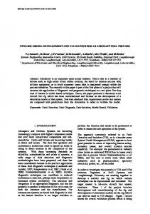
4 Integrated Simulation Environment This integrated simulation environment is developed based on the test results of vehicle integrated with AWD module. Figure 5 is a test vehicle for the integrated vehicle test. The vehicle test follows the protocol of acceleration test and slalom test. The acceleration test is for verification of longitudinal vehicle modelling, and the slalom test is for verification of lateral vehicle modelling. Because this simulation environment’s goal is for verification of control logic, in this test, AWD module is controlled with fully engaged (4WD) mode and fully disengaged (2WD) mode.
5
MATEC Web of Conferences 167, 02011 (2018) https://doi.org/10.1051/matecconf/201816702011 IC4M & ICDES 2018 MATEC Web of Conferences
Figure 5. Integrated Vehicle Test
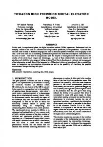
Figure 6. Lateral Simulation Model Verification
6
MATEC Web of Conferences 167, 02011 (2018) https://doi.org/10.1051/matecconf/201816702011 IC4M & ICDES 2018 IC4M 2018
Figure 7. Longitudinal Simulation Model Verification
Figure 6 and 7 are comparison between integrated vehicle test and integrated simulation environment. Generally lateral vehicle modelling verification is conducted by comparison of lateral acceleration and yaw rate [6], and figure 6 tells that correlation is over than 99%. Moreover, longitudinal vehicle modelling verification is conducted by comparison of longitudinal velocity, and figure 7 shows that the correlation is over than 99% [7]. In conclusion, high precision vehicle simulation environment for AWD control logics is developed.
References 1. 2.
3. 4.
5.
6. 7.
C. Senatore, C. Sandu, M.M. Torque distribution influence on tractive efficiency and mobility of off-road wheeled vehicles (Journal of Terranmechnics, 2011) T. D. Gillespie, Fundamentals of Vehicle Dynamics, (SAE, 1992) Thomas E. Scott, Power Transmission (Prentice Hall, 2000) J. Reimpell, H. Stoll, J. W. Betzler, The Automotive Chassics : Engineering Principles 2nd Edition (Butterworth-Heinemann, 2001) Katsuhiko Ogata, System Dynamics (Prentice Hall, 2004) U. Kiencke, L. Nielsen, Automotive Control Systems : For Engine, Driveline and Vehicle 2nd Edition (Springer, 2004) Julius S. Bendat, Allan G. Piersol, Random Data : Analysis and Measurement Procedures (WILEY, 2010)
7