FUJIFILM's newly-developed 'AMULET', a digital mammography system,
simultaneously realizes .... source of the AMULET.2) Mo and Rhodium (Rh) can
be set.
UDC 616-073.75+618.19-006+771.537
Development of High-sensitivity and High-resolution Digital Mammography System ‘AMULET’ Kaku IRISAWA*, Takahisa ARAI*, Hajime NAKATA*, Tomonari SENDAI*, Takao KUWABARA*, and Katsutoshi YAMANE* Abstract FUJIFILM’s newly-developed ‘AMULET’, a digital mammography system, simultaneously realizes high-image quality, low-dose image acquisition and high-throughput as well as patient-oriented design. A detector mounted on AMULET directly converts X-ray signals into electronic signals to readout the electronic signals by using a uniquely developed “Direct Optical Switching” readout method in its imaging process. This detector with dual amorphous Se layers makes it possible to deliver high-definition diagnostic images consisting of 50 μm-size pixels providing the finest resolution among direct-conversion X-ray image detectors. Well-optimized Auto-Exposure-Control between the direct-conversion detector and an x-ray tube with Mo and W targets can meet the wide range of diagnostic needs from high-image quality to low-dose exposure. Moreover, ergonomic design helps to alleviate patient’s discomfort.
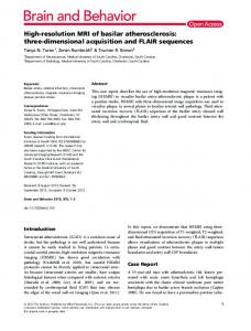
1. Introduction FUJIFILM succeeded in development of X-ray image sensor which “directly converts” X-ray signals into electric signals and converts the electric signals into digital images by our unique “Optical Switching Readout”, and paved the way for acquiring high-resolution images consisting of 50 μm-size pixels, which is the smallest pixel size in the world in the field of the high-definition sensor using an amorphous selenium semiconductor. A digital mammography system equipped with this image sensor AMULET (Fig. 1) realizes
Fig. 1 System configuration of AMULET (FDR MS-1000).
Original paper (Received November 20, 2009) * Equipment Research & Development Center Research & Development Management Headquarters FUJIFILM Corporation
FUJIFILM RESEARCH & DEVELOPMENT (No.54-2009)
high-definition, reduction of exposure dose and favorable throughput at high levels. In this report, background of development, system configuration and features, and performances of this system will be briefly described.
2. Background of Development Breast cancer currently shows the highest prevalence rate of cancer incidences among Japanese women, and the mortality rate of the breast cancer is increasing year by year. Therefore, breast cancer screening mainly with mammography has now become popular for the purpose of early detection of the breast cancer and, simultaneously, introduction of a digital mammography system is now in progress in association with recent digitalization in medical practice. FUJIFILM succeeded in digitalization of X-ray diagnostic images by a Computed Radiography (CR) System ahead of all other manufactures in the world. From then on, we continue to supply digital X-ray image diagnostic devices to the market, and has started selling CR system mammography image scanner PROFECT in 2003. Consequently, we have gained good reputation as being easy to digitalize in combination with an existing X-ray source. The digital mammography is high in X-ray usage efficiency in comparison with conventional film/screen systems and has an expanded dynamic range. Therefore, it is superior in visualization of tumor masses and is able to reduce the exposure dose. On the other hand, it is said
Miyanodai, Kaisei-machi, Ashigarakami-gun, Kanagawa 258-8538, Japan
11
that sharpness is poor because there is a limit due to the pixel size. Even though 50 μm, which is a relatively fine grained pixel size, is realized in PROFECT, the pixel sizes of the digital mammography systems combined with commercially available X-ray sources and flat-panel detectors (FPD) still range from 70 to 100 μm. In the mammography diagnosis, presence or absence, distributions, and shapes of minute calcification smaller than 1 mm are important indices in diagnosis. Therefore, there is a persistent demand for finer pixels. As benefits of digitalization, there are great expectations for improvement of general convenience in the mammography screening and diagnosis such as high-throughput imaging, high-eff iciency image control on the basis of image processing, image display, and network establishment, and high-efficiency and high-precision diagnosis on the basis of past-image comparison and computer-assisted diagnosis. The imaging throughput of FPD system is generally higher than that of the CR system using cassettes. However, there is a tendency that the throughput of the FPD system is lowered with enhancement of image quality, and hence improvement in this point is required. In the background as described above, we have done research with a new digital mammography system which allows subjects to have a check-up with a safe conscience, allows doctors to make a diagnosis easily, and allows operators to handle easily, and have developed AMULET (Type: FDR MS-1000) which achieves improvement of diagnostic performances owing to high-sensitivity and high-resolution, reduction of exposure dose, and favorable throughput.
3. System Configuration of AMULET As show n i n Fig. 1, A M U LET is composed of a mammographic unit and a console (operating station). Images taken by the mammographic unit are processed and displayed in the console, so that we can save and use these images in external servers or applications via network. The mammographic unit is composed of an X-ray source unit which emits X-rays, and a newly developed image sensor unit which detects X-ray images passed through breasts of subjects. Parts of these units where the subjects come in contact with are designed to alleviate pain or chill and to stabilize the body position. The image sensor, the X-ray source, and the ergonomics design being friendly to the subjects as characteristics of AMULET will be described below.
3.1
Image Sensor
AMULET is equipped with a sensor with the world’s smallest pixel size of 50 μm as a high-quality X-ray sensor using an amorphous selenium semiconductor as mentioned at the outset. A schematic view of the image sensor is shown in Fig. 2.
12
Fig. 2 Schematic view of the novel image sensor.
The sensor is formed with Stripe Transparent electrodes (Stripe electrodes) connected to Charge Amplifier ASICs, Readout Photoconductive Layer (Readout PCL), Electronic Trapping Layer (ETL), X-ray Photoconductive Layer (X-ray PCL), and Top electrode on a glass substrate. The sensor is also provided with a Linear readout optics orthogonal to the Stripe Transparent electrodes, and Erasure optics on the lower side of the substrate. Functions of the respective layers of this sensor and the principles of imaging will be described below. The X-ray image sensor generally acquires X-ray images by the processes of (a) conversion from X-rays to electric charges, (b) electric charge trapping, and (c) electric charge readout. In the X-ray imaging, the smaller the X-ray dosage at the time of imaging, the fewer doses the subject to be imaged is exposed. Therefore, what is essential to be a good sensor is acquiring images with least degradation in S/N ratio and sharpness of the X-ray image at the time of incoming into the sensor in the above-mentioned processes performed in the sensor. A “Direct Conversion” System is a system of converting X-ray signals into electric signals using the so-called photoconductive phenomenon such that when irradiating a semiconductor applied with voltage with X-rays, the energy of the X-ray quantum is absorbed by electrons in the semiconductor, becomes free electrons and free holes ultimately, and are transported according to the electric field. In the case of the Direct Conversion System, the direction of travel of the signal charge is determined by the electric field, and hence degradation of sharpness is negligible. In contrast, in an “Indirect Conversion” System, X-rays are irradiated on a layer of fluorescent material which affords a high X-ray absorbance, is converted into visible light, and then is converted into electric signals by a light-receiving element such as a photodiode or a CCD. In this system, sharpness is deteriorated because the fluorescence is emitted
Development of High-sensitivity and High-resolution Digital Mammography System ‘AMULET’
Fig. 3 Cross-section of the sensor, and its imaging process from (a) to (c).
Amorphous selenium has a capability of absorbing 90% or more of X-rays generated from the mammography X-ray source and converting the same into electric charge. In addition, the quantity of electrons trapped during movement is reduced by using high-purity selenium containing minimum impurities, so that the electrons are collected on the ETL with efficiency. In this configuration, degradation of the sharpness and S/N ratio in the process from the X-ray charge conversion to the electron trapping is reduced. Another feature of this sensor is a configuration composed of the ETL, Readout PCL (amorphous selenium), and Stripe Transparent electrodes in order to realize “Optical Switching Readout” using Photoconduction Effect (Photoinduced Discharge Effect). As shown in Fig. 3(b), positive charge is induced to electrodes and electric fields are formed in Readout PCL in a state in which the electrons are trapped in the ETL. When readout light is irradiated from the Transparent Electrode side in this state, free electronsholes pairs are generated in the Readout PCL as shown in
FUJIFILM RESEARCH & DEVELOPMENT (No.54-2009)
Fig. 3(c). The generated holes are moved to the trapped electrons and are neutralized, and the electrons are detected by a charge amplifier connected via the electrodes and are converted into signals. As the quantity of generation of the free electron-hole pairs corresponds to the quantity of the trapped electrons, the quantity of the detected signals corresponding to the quantity of the trapped electrons is obtained. After having readout, an afterimage is efficiently deleted by irradiating the entire surface of the sensor with high-luminance light from the Erasure optics, so that shortening of the imaging cycle is achieved. In Optical Switching Readout, high-resolution images composed of 50 μm × 50 μm pixels are acquired relatively easily by causing the Linear readout optics to emit light at every 50 μm against the substrate formed with Stripe Electrodes at a 50 μm pitch. As it does not have gate lines extending orthogonally to Readout Lines or TFTs as in a TFT Readout System and the parasitic capacity of the Readout Lines is small, readout with low noise is achieved. When reducing the pixel size, as the number of orthogonal portions of lines and the TFTs further increase in the case of the TFT Readout System, advantages of Optical Switching Readout are brought to the fore. Therefore, in the case of the newly developed sensor, the amount of electric noise added at the time of readout is small, and thus degradation of the S/N ratio at the time of the sensor output with respect to the S/N ratio which is originally possessed by the X-ray images can be minimized, so that a structure which allows reduction of pixel size while restraining degradation of the image qualities such as sensitivity or Detection of Quantum Efficiency (DQE) is certainly achieved.1) Although reduction of the pixel size under the TFT manufacturing rules in the sensors of Indirect Conversion System or Direct Conversion System leads to degradation of the image qualities, the newly developed sensor is expected to be able to reduce the pixel size while maintaining high-definition as shown in Fig. 4.
Direct conversion + Direct Optical switching readout
Image Quality
isotropically and, in addition, light scattering cannot be avoided in a section from the light-emitting unit to the light-receiving element. If the thickness of the layer of fluorescent material is reduced for maintaining the sharpness, the sensitivity of the sensor is lowered due to lowering of X-ray absorbance. Therefore, it is difficult to secure both the sharpness and the sensitivity in the Indirect Conversion System. Therefore, the Direct Conversion System using the amorphous selenium semiconductor as the X-ray PCL is employed in the newly developed image sensor. The Top electrode is irradiated with X-rays in a state of being applied with negative voltage, and generated free electrons are collected on the ETL by the electric field as shown in a crosssectional view of the sensor taken in the direction of the Stripe Electrodes shown in Fig. 3(a), and an electronic latent image is formed as shown in Fig. 3(b).
Indirect conversion +TFT㻃 readout
100 μm
Direct conversion +TFT㻃 readout
75 μm
50 μm
Pixel size Fig. 4 Relation between image quality and pixel size in each imaging method.
13
3.2
X-ray Source
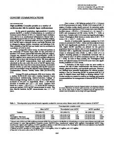
As the newly developed image sensor is superior in dynamic range and linearity in comparison with the conventional film/screen system, high flexibility is ensured when selecting an X-ray dosage or an X-ray quality. In addition, by increasing the thickness of the X-ray PCL, the high-energy X-ray absorbance is easily increased in comparison with the conventional films or imaging plates. In order to make the vast use of advantages of the sensor as mentioned above, Tungsten (W) target, which is advantageous for low does exposure, is mounted in addition to Molybdenum (Mo) target, which is currently widely used in the X-ray source of the AMULET.2) Mo and Rhodium (Rh) can be set to an X-ray filter, and the target/filter combination (T/F) is selectable from three types; Mo/Mo, Mo/Rh, and W/Rh. Fig. 5 shows a relations between the ratio of the image contrast to the image noise (CNR) of Al having a thickness of 0.2 mm at each T/F and PMMA which simulates a breast having 50% of mammary gland and 50% of fat.
Fig. 5 Relation between CNR under achievable-AGD at each T/F and PMMA thickness.
The term CNR here means a highest CNR obtained by a combination of the X-ray tube voltage and mAs value under Achievable (see Fig. 6) average glandular dose (AGD), which is an index of degree of does exposure, on the basis of EUREF standard3).
Fig. 6 PMMA thickness dependences of CNR and AGD at each AEC mode.
14
When the PMMA thickness is small, sufficiently high CNRs are obtained with the combination of Mo/Mo. However, the CNR is gradually lowered with increase in thickness and the difference from the Mo/Rh combination is increased correspondingly and, finally, it underruns the limit CNR. With the combination of W/Rh, it is understood that the CNR is high even when the PMMA is thick, and as it has a hard radiation quality having X-ray quantum distributed in high energies, a sufficient X-ray transmittance is obtained even with a thick breast. Also, as the CNR is the highest with the combination of W/Rh at every PMMA thickness, it implies that the exposure dose can be further reduced by employing the combination of W/Rh. AMULET has Automatic Exposure Control (AEC) mechanism which is adapted to set the irradiation doses of these three types of T/F automatically according to the breast thickness to reduce the labor of operators. The exposure control is performed using an image sensor and an independent AEC specific substrate. With the employment of the specific substrate, signal charge at the time of preexposure for determining the irradiation dose can be added to the signal charge of the real exposure in the image sensor, so that the readout is achieved at one try. Therefore, the readout noise is not added needlessly, and the degradation of the image quality is reduced. At the automatic imaging in the use of the AEC, the operator selects one of three modes; H_ MODE (high-definition), L_MODE (standard image quality), and W_MODE (low-dose exposure). The T/F-switched breast thicknesses and the X-ray tube voltage values are determined on the basis of the physical evaluation as described above, and image evaluation of resected samples of breast cancer performed in cooperation with a group of Dr. Tokiko Endo in National Hospital Organization Nagoya Medical Center. As a result of visual evaluation of calcification or tumor mass in resected samples of breast cancer having various thicknesses, it became evident that the granularities of the sample images well correspond to the CNRs. It also became evident that the sharpness relating to the visibility of the calcification or the tumor mass is increased with increase in softness of T/F. In other words, optimum diagnostic images are acquired by selecting as soft T/F as possible within an allowable range in terms of granularity4). Fig. 6 shows PMMA thickness dependencies of AGD and CNR at tube voltages and mAs values set in H, L, and W_MODEs. The T/Fs selected in H and L_MODEs are shown by background colors. The T/F is selected in the order of Mo/Mo, Mo/Rh, and W/Rh according to the increase of the PMMA thickness. In H_MODE, as a higher priority is put on the image quality, the AGD is set to a value closer to Acceptable to provide images with highest granularity and sharpness. In L_MODE, images with consideration given to the balance between the AGD and the granularity are provided. Therefore, with the combination of W/Rh, imaging of high-definition with consideration given to reduction
Development of High-sensitivity and High-resolution Digital Mammography System ‘AMULET’
3.3
Subject-Friendly Ergonomics Design
As arm rests of the mammographic unit, a chest wall portion and side portions of the sensor are portions where the subjects come in direct contact with at the time of imaging, we aimed at the design which allows subjects to have a check-up with a sense of security and stability. Fig. 7 shows a schematic view of armrests and a chest-wall pad of AMULET.
Fig. 7 Armrests, and chest-wall and axillary pads of AMULET.
In view of opinions of the operators saying that the subjects have a difficulty to place their arms naturally during imaging in the cephalocaudal (CC) direction in the conventional system, the handles are inclined toward the subject with respect to the imaging table, so that the subject can place her arms naturally. Portions of the unit corresponding to the portion of the body of the subject from the arms to the hands during the imaging in the mediolateral oblique (MLO) direction are designed to be a roundish form without level difference, and soft material is used for the armrests, so that the pain of the arms is alleviated. In addition, urethane foam pads (disposable and replaceable parts) are provided for the chest-wall and auxiliary cavities to alleviate the pain at the chest when being pressed against during the imaging.
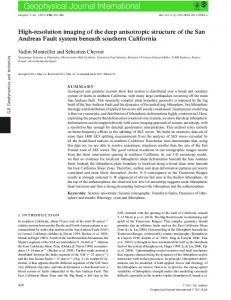
RQA-M2 condition (Mo/Mo, 28kv, Al filter; 2mm) is employed for the quality of radiation. 60 125μGy 71 36
50
DQE 䚭(%)
of exposure dose for subjects having a thick breast which is subjected to a large amount of exposure is achieved. In W_MODE, the combination of W/Rh is used irrespective of the breast thickness, and images having maximum allowable level of granularity for diagnosis while putting a priority on low-dose exposure. By using the combination of W/Rh, an AGD lower than the Achievable AGD is also possible. Evaluations of the clinical value in such low-dose range are now in progress and reduction of risk for young subjects is expected.
40 30 20 10 0 0
2
4
6
8
10
-1
Spatial frequency䚭/䚭mm
Fig. 8 DQEs of AMULET at various doses.
In general, in the sensor having the pixel size x, DQE is significant up to a frequency of 1/2x, and the smaller the pixel size, the higher frequency components in the image can be converted into the electric signals according to Nyquist Theorem. As AMULET is able to readout images with 50μm pixels, frequency components as high as 10 mm -1 in the image can be converted into electric signals, so high DQEs are shown in a range of practical dose from 71 to 125 μGy. This indicates that the Direct Conversion using Amorphous Selenium having a high level of X-ray absorbance and FUJIFILM’s unique Optical Switching Readout contribute to improvement of S/N ratio in the fine pixels, and are extremely effective for achievement of both high-sensitivity and highresolution. It also indicates that AMULET is a system which is capable of keeping the lowering of the DQE to the fraction of approximately 13% even with a dose as low as 36 μGy, and is not much affected by the readout electric noise. Fig. 9 shows a result of Contrast-Detail phantom evaluation for evaluating the visibility of Au columns having different diameters and thicknesses under the EUREF-compliant conditions3) (Mo/Mo, 28 kV) as the visual evaluation.
4. Performances of AMULET Fa ct or s wh ich con st it ut e t he i mage qu al it y of mammography include image contrast (signals), sharpness, granularity (noise), and frequency-dependencies of DQEs including these factors are widely used as a comprehensive index for evaluating the image quality. Fig. 8 shows DQEs of AMULET measured under the IEC-compliant conditions5).
FUJIFILM RESEARCH & DEVELOPMENT (No.54-2009)
Fig. 9 Contrast-detail curves for AMULET for three different doses at Mo/Mo, 28kV.
15
(a) Image with AMULET.
(b) Image with PROFECT.
Fig. 10 Image comparison of the resected breast specimen6).
In this image, a curve obtained by connecting plots of respective doses is a boundary between possible and impossible of visual identification of Au column, and it indicates that the more it shifts to the smaller side in diameter and thickness, the smaller objects in the breast are visually identified. The visibility of AMULET is sufficiently beyond the boundary of Acceptable even with a dose as low as 61 μGy. As regards the dose of small nozzle area 105 μGy, which is approximately equal to the normal dose, the visibility is significantly beyond the boundary of Achievable on the side of smaller thicknesses and diameters, so that the improvement of visual identification of calcification is expected. Fig. 10 shows images of a calcified portion of a resected sample of breast cancer taken by AMULET and PROFECT in an enlarged scale6). The resected sample of breast cancer having a thickness of 40 mm is placed on a PMMA having a thickness of 5 mm to simulate a breast having a thickness of 45 mm in total, and is taken under the conditions of Mo/Rh, 28 kV, 42 mAs. The image taken by AMULET is superior in granularity as a whole, and shows the shape and the boundary of calcification clearly and three-dimensionally. Fat and mammary gland tissues in the periphery also come out more clearly. Finally, the imaging throughput of AMULET will be described. Amorphous Selenium induces afterimages because it contains much charge trapping caused by impurities, which might cause deterioration of the throughput. In contrast, in the newly developed image sensor, the charge trapping is reduced by using high-purity selenium, and formation of the afterimages is reduced by the structure which allows irradiation of the Erasure optics over the
16
entire surface. Incidentally, when handling high-resolution images, the volume of the image data is significantly large, and it requires a fair amount of time for image processing. However, AMULET is provided with a specific substrate for performing image processing on the image data in parallel. With these countermeasures, a target of “intervals of 15 seconds at maximum for the identical subject” (set on the basis of research conducted by FUJIFILM), which is demanded by users, is expected to be achieved.
5. Conclusion With digital mammography system AMULET, highsensitivity and high-resolution images are acquired with the provision of an image sensor characterized by Direct Conversion by amorphous selenium and Optical Switching Readout. In addition, imaging according to a wide range of needs from high-definition to low-dose exposure is achieved briefly by the X-ray source having targets of Mo and W coupled with the image sensor. Furthermore, AMULET has a design with consideration to alleviation of physical and psychological burden of the subjects. At the moment, there is no other product which has achieved both high-definition and enhanced throughput like AMULET, and contribution to improvement of accuracy and efficiency of mammography screening and diagnosis and alleviation of burden of subjects, as well as to early detection and improvement of prognosis of breast cancer are expected. The high-performance digital mammography system AMULET in association with PROFECT which allows advantages of existing X-ray sources enables us to propose digital mammography solutions suitable to circumstances of respective hospitals.
Development of High-sensitivity and High-resolution Digital Mammography System ‘AMULET’
References 1) K. Irisawa et al. Proc. SPIE. 7258, 72581I-1-72581I-10 (2009). 2) P. Bernhardt et al. Med. Phys. 33 (11), 4337-4349 (2006). 3) European guidelines for quality assurance in breast cancer screening and diagnosis. 4th ed. Luxembourg, European Communities, 2006. 4) T. Kuwabara et al. Proc. SPIE. 7258, 72584P-1-72584P-12 (2009). 5) I EC 62220 -1-2: Medical elect r ical equipment – Characteristics of digital x-ray imaging devices – Part 1-2: Determination of the detective quantum efficiency – Detectors used in mammography, 2007. 6) Tokiko Endo, Handbook of Interpretation of Radiogram of Mammographic Image. 2nd Ed. Osaka, Nagai-Shoten, 2008, 193p. (In this report, “AMULET” and “FUJIFILM” are registered trademarks of FUJIFILM Corporation.)
FUJIFILM RESEARCH & DEVELOPMENT (No.54-2009)
17