The International Archives of the Photogrammetry, Remote Sensing and Spatial Information Sciences, Volume XLI-B5, 2016 XXIII ISPRS Congress, 12–19 July 2016, Prague, Czech Republic
DEVELOPMENT OF IMAGE SELECTION METHOD USING GRAPH CUTS T. Fuse a, * and R. Harada a a
Dept. of Civil Engineering, University of Tokyo, Hongo 7-3-1, Bunkyo-ku, Tokyo, 113-8656, Japan -
[email protected],
[email protected] Commission V, WG V/4
KEY WORDS: Image Selection, Bundle Adjustment, Network Design, Graph Cuts, 3D Measurement, Visualization
ABSTRACT: 3D models have been widely used by spread of many available free-software. Additionally, enormous images can be easily acquired, and images are utilized for creating the 3D models recently. The creation of 3D models by using huge amount of images, however, takes a lot of time and effort, and then efficiency for 3D measurement are required. In the efficient strategy, the accuracy of the measurement is also required. This paper develops an image selection method based on network design that means surveying network construction. The proposed method uses image connectivity graph. The image connectivity graph consists of nodes and edges. The nodes correspond to images to be used. The edges connected between nodes represent image relationships with costs as accuracies of orientation elements. For the efficiency, the image connectivity graph should be constructed with smaller number of edges. Once the image connectivity graph is built, the image selection problem is regarded as combinatorial optimization problem and the graph cuts technique can be applied. In the process of 3D reconstruction, low quality images and similar images are also extracted and removed. Through the experiments, the significance of the proposed method is confirmed. It implies potential to efficient and accurate 3D measurement.
1. INTRODUCTION 3D models have been widely used by spread of many available free-software. According to the population of such 3D models, the application of the models can cover wide variety of fields. Additionally, enormous images can be easily acquired, and images are utilized for creating the 3D models recently. The creation of 3D models by using huge amount of images, however, takes a lot of time and effort, and then efficiency for 3D measurement are required (Agarwal et al., 2009). In the efficient strategy, the accuracy of the measurement is also required. Generally, specifications and configurations of cameras are set in advance as project planning, which is so called as network design (Atkinson, 1996). The network design mainly consists of zero-order design (ZOD: the datum problem), first-order design (FOD: the configuration problem), second-order design (SOD: the weight problem), and third-order design (TOD: the densification problem). One of the most important elements among the network design is the FOD. Considering the availability of huge amount of images, the network design may be applied in order to select images among them after taking the images. The image selection based on the network design will be expected to contribute improvement of efficiency for the 3D measurements and keeping of accuracy simultaneously. This paper presents an image selection method based on network design for huge amount of images, and shows the effectiveness of the proposed method. Specifically, the proposed method uses image connectivity graph. The image connectivity graph represents the relationships between images by using node as an image and edges as relationships between two images. The edges in the graph have costs, which are
defined by elements in the FOD. The estimation accuracies of exterior orientation elements, namely variances of estimated camera positions between two images, are set as the costs. For the efficiency, the image connectivity graph should be constructed with smaller number of edges. Once the image connectivity graph is constructed, the image selection problem is regarded as combinatorial optimization problem. Against the combinatorial optimization problem, the graph cuts technique can be applied. The graph cuts technique is formulated as energy minimization. Here, the cost in the image connectivity graph is considered as the energy, and then technique can find the optimized image connectivity graph in the sense of cost minimization with smaller number of edges as possible. The remaining edges are corresponding to selected image pairs. Additionally, in the process of 3D reconstruction, low quality images and similar images are also extracted and removed. The low quality images have only small number of feature points, and the image can be specified according to the image matching result. The similar images have small baseline length compared with average distance from the images to 3D reconstructed feature points. Through the process, the efficiency of the image selection will be expected. 2. AUTOMATIC IMAGE SELECTION METHOD FOR 3D MEASUREMENT 2.1 Framework of the Proposed Method This section presents a pipeline of the proposed method (Figure 1). In this study, camera calibration is conducted in advance, namely the interior orientation elements (intrinsic parameters matrix) are given (Zhang, 2000). Then, image matching is carried out for image pairs from the set of images, and image
* Corresponding author
This contribution has been peer-reviewed. doi:10.5194/isprsarchives-XLI-B5-641-2016
641
The International Archives of the Photogrammetry, Remote Sensing and Spatial Information Sciences, Volume XLI-B5, 2016 XXIII ISPRS Congress, 12–19 July 2016, Prague, Czech Republic
coordinates of feature points that are common to the image pairs are determined. According to the result of the image matching, image pairs with small number of feature points, that is low quality images, are detected and removed. Furthermore, with the image coordinates of each feature point provided by the image matching, exterior orientation elements of the image pair and 3D coordinates of the feature points are estimated through relative orientation and intersection. Here, the detection and removal of the similar images are also applied. The similar images detection is based on base-height ratio. With the 3D coordinates of the feature points and exterior orientation elements between each image pair, the estimation accuracy of the exterior orientation elements are calculated by applying bundle adjustment (Luhmann et al., 2014). Finally, the relationships between images are represented as an image connectivity graph based on the estimation accuracy of the exterior orientation elements. Once the image connectivity graph is constructed, the image selection problem is regarded as the combinatorial optimization problem to reduce number of edges. To solve the optimization problem, graph cuts technique is applied.
Camera calibration
Image matching for images pairs (2.2) (Removal of low quality image pairs)
Estimation of exterior orientation elements and feature points’ 3D coordinates (2.3) (Removal of similar images)
Exterior orientation elements estimated by bundle adjustment between image pairs (2.4)
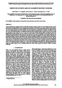
integration images. The integration images improve computational speed. Additionally, points included in a certain radius circle are added for calculation of norm, and then orientation is adopted with maximum norm. According to above mentioned features, the SURF is robust against scaling and rotation. The image is divided into 4 x 4 block, and then differences of features are represented as 64 dimension SURF features by using those gradient and amplitude ( dx, dx, dx , dy ). Figure 2 shows an example of feature points tracking by the SURF in our experiments.
Figure 2. Feature points tracking by SURF Even if the SURF is applied to feature points extraction and tracking, incorrect matching points are still exist. The feature points tracking are refined by using not only adjacent frames also sequential frames. Firstly, extracted feature points are searched in sequence between adjacent frames. After the tracking process within a certain number of frames, position of feature points are re-projected into first frames (back matching). If the displacement between first and last position of the points is larger than a threshold, the feature points are discarded. With the result of the matching, 3D coordinates of the feature points can be calculated. When the depth of the points is larger than a threshold, the feature points are also discarded. After the above mentioned thresholding process, incorrect matching points still remain. Especially in the case of application in urban area, similar textures make such incorrect matching. In this study, RANSAC (Random Sample Consensus) (Fischler and Bolles, 1981) is also applied. RANSAC algorithm is a method of outlier removal. Finally, the remaining points are accepted as feature points (Figure 3).
Connectivity graph representation of the relations between the images (3.1)
Image automatic selection by the combinatorial optimization (graph cuts) (3.2) Figure 1. Pipeline of the proposed method
2.2 Image Matching Firstly, feature points extraction and tracking are conducted for applying relative orientation as initial relationships between images. Recently, sophisticated feature points extraction and tracking algorithms have been developed. One of the most reliable algorithms is SURF (Speeded-UP Robust Features) (Bay et al., 2008). The SURF algorithm is applied to feature points extraction and tracking. The SURF algorithm uses box filter, which approximates Hessian-Laplace detector, for making
Figure 3. Feature points tracking refinement Results of the image matching are used for reducing number of image pairs. When the number of tracked feature points is less than a certain threshold, the image pair is regarded as low quality image. The low quality image pair is removed for the following process. 2.3 Exterior Orientation Estimation and 3D Reconstruction Using the image coordinates of the feature points and interior orientation elements in each image provided as a result of the previous matching, exterior orientation elements and 3D coordinates of the feature points are estimated through relative orientation and intersection (Hartley and Zisserman, 2004). Through the relative orientation and intersection, translation
This contribution has been peer-reviewed. doi:10.5194/isprsarchives-XLI-B5-641-2016
642
The International Archives of the Photogrammetry, Remote Sensing and Spatial Information Sciences, Volume XLI-B5, 2016 XXIII ISPRS Congress, 12–19 July 2016, Prague, Czech Republic
vector “t”, rotation matrix “R”, and 3D coordinates of feature points “X” can be calculated.
removal of the similar images is carried out in a 3D reconstruction process.
When a camera position is translated with t and rotated with R in a fixed world coordinate system, the 3D coordinates X=(X, Y, Z)T are projected to image coordinates x=(x, y)T. Let the intrinsic parameters matrix of the camera be “K”. The geometric relationship between 3D coordinates and image coordinates are expressed by using homogeneous coordinates
2.4 Accuracy Evaluation of Exterior Orientation Elements
X X Y Z 1 and x x y 1 . T
T
x KRT I | t X
(1)
Where, I is 3 x 3 unit matrix, and “ ” represents equivalence except for scale. By applying eight-point algorithm (Hartley, 1997) to the feature points in images, fundamental matrix “F” is estimated. When the intrinsic parameters matrices are same between images, the fundamental matrix becomes as follows.
In order to construct an image connectivity graph based on the FOD, estimation accuracy of exterior orientation elements is required. Once initial value of the orientation elements and 3D coordinates of the feature points are acquired, bundle adjustment can be separately applied to each image pair to calculate the estimation accuracy (Luhmann et al., 2014). The feature points have coordinates (Xi, Yi, Zi). The each sequential image has a 3D coordinates (Xj, Yj, Zj) as the camera position. At the frames j, the feature point i has camera coordinate system (xij, yij). A transformation between the camera coordinate and the world coordinate systems represents collinearity equation.
F (K 1)T (t R)K 1
yij yij yij c
where
E K T FK
With the 3D reconstruction in each image pair, the image pairs as similar images are also detected. Using the 3D coordinates of the feature points in each image pair, average distances between left image (origin of the 3D coordinates is set as (0, 0, 0)) and the feature points in the 3D coordinates are calculated. When a 3D coordinates of a certain feature point pi are (Xi, Yi, Zi), the distance is found with
M
H pq
i 1
X i2 Yi 2 Z i2
(4)
M
Using the length of baseline Bpq and the average distance Hpq, similar images can be detected. When the average distance between an image pair and feature points is much larger compared with the length of baseline, degree of similarity between the image pair becomes higher. Accordingly, when base-height ratio Bpq/Hpq is smaller than a certain threshold, the image pair can be discriminated as a similar images. In such a case, one of the image pair is removed. In the manner, the
Z Z
Z Z
a21 a31
i i
j
22
j
32
i
j
23
i
i
j
33
i
(5)
j
j
akl = factors of rotation matrix The position and rotation updates are computed iteratively by minimizing an objective function of the re-projection error. In order to solve the bundle adjustment problem, LevenbergMarquardt method (Hartley and Zisserman, 2004) is applied. The objective function E is approximated by the following formula:
1 E x x E x gT x xT H x 2 H I x g g
where
dE dx
(6) (7)
(gradient) x
d 2E H dx 2
(Hessian) x
= dumping factor
X i2 Yi 2 Zi2 .
When the number of feature points at a certain image pair is M, the average distance Hpq between the image pair (p-th and q-th frames) and the feature points in 3D coordinates is defined as follows.
Y Y a Y Y a
c = focal length xij , yij = factors of interior orientation
(3)
By applying singular value decomposition to the essential matrix, the translation vector t and the rotation matrix R can be calculated (Kanatani, 1996). Since the translation vector t has scale ambiguity, the absolute value of t (length of baseline) between adjacent images is defined as being equal to 1. In this study, a set of images is a sequential image, and then the adjacent images are considered as adjacent frames. Namely, length of baseline Bpq (between p-th and q-th frames) is defined as q-p (q>p). Based on the above mentioned exterior orientation elements, 3D coordinates of feature points are estimated by intersection.
X a X a
a31 X i X j a32 Yi Y j a33 Z i Z j
(2)
According to the intrinsic parameters matrix, essential matrix “E” is derived from the fundamental matrix.
X X
a11 X i X j a12 Yi Y j a13 Z i Z j
xij xij xij c
Only here, x expresses parameters vector, not image coordinates. For simplicity, only position of camera (translation vector), that is the most important element of the network design, is considered in exterior orientation elements. When the translation vectors between an image pair are estimated as t = (TX, TY, TZ)T by relative orientation, and t’ =(TX’, TY’, TZ’)T by bundle adjustment, the estimation accuracy is defines as follows. 2
1
(8)
T2 T2 T2 X
Y
Z
Where, TX TX TX ' , TY TY TY ' , TZ TZ TZ ' , respectively. The estimation accuracy is used as cost of image connectivity graph in next chapter.
This contribution has been peer-reviewed. doi:10.5194/isprsarchives-XLI-B5-641-2016
643
The International Archives of the Photogrammetry, Remote Sensing and Spatial Information Sciences, Volume XLI-B5, 2016 XXIII ISPRS Congress, 12–19 July 2016, Prague, Czech Republic
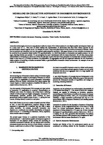
3. AUTOMATIC IMAGE SELECTION BY COMBINATORIAL OPTIMIZATION 3.1 Image Connectivity Graph as Relationships between Images Based on Network Design A graph representation of relationships between the images is performed based on graph theory (Busacker and Saaty, 1965). In the graph, each image is set as a node, and the nodes are connected by edges. The edge represents connectivity, which means that the two images has common feature points and are used for final bundle adjustment. The edge has cost defined by estimation accuracy of exterior orientation elements of the two images, namely variance of estimated camera positions between the two images. The estimation accuracy is a part of the FOD, which is thought to be the most important element in the network design. The graph is called as image connectivity graph, which makes relationships between images to be represented based on network design (Figure 4). 3.2 Automatic Image Selection by Applying Combinatorial Optimization Problem Image selection is considered as edge reduction in the image connectivity graph. Once the image connectivity graph is constructed, automatic image selection can be regarded as combinatorial optimization problem. To solve the problem, graph cuts technique can be applied (Bishop, 2006). 3.2.1 Graph cuts: We consider graph structure G=(V, E) with set of nodes V and set of edges E, firstly. An initial node s and a terminal node t are specified (s V, t V). Subset S of V includes the initial node s and excludes the terminal node t, and another subset T of V excludes the initial node s. Dividing total set of nodes V into subsets S and T is called as cuts. Edges started from subset S to end nodes outside of S is referred as cut edges, and sum of costs of cut edges is defined as volume of cut U(S, T). When an edge cost between nodes u and v is expressed as c(u, v), the volume U(S, T) is defined as follows. U (S , T )
c u, v
(9)
uS , vT
Among patterns of graph cuts, a cut minimizing the cut volume is called as min-cut.
One of the representative algorithms to make min-cut is FordFulkerson’s method. Before explaining the algorithm, subsidiary network is introduced. The subsidiary network expresses additive volume, when costs of edges and flow are given in a graph. When a cost of an edge between node u and v is c(u, v), and a flow from node u to node v is f(u, v) (c(u, v) > f(u, v)), the additive volume is equal to c(u, v) - f(u, v). The sum of the additive volume with regard to all edges is subsidiary network. Using the subsidiary network, the algorithm calculates the min-cut as follows: 1) set initial flows (e.g. all flows are equal to 0); 2) search paths (consists of edges from initial node to terminal node), in which flow can be increased, in a subsidiary network; 3) select a path P, and calculate minimum value of additive volume P, and then add the P on the path P; 4) repeat 2) and 3) until paths, in which flow can be increased, do not exist; 5) finally, set subset of nodes, which can be reached from initial node in the subsidiary network, as S, and T from terminal node. 3.2.2 Image selection based on graph cuts: Applying above mentioned graph cuts to the image connectivity graph, image selection is accomplished. The graph cuts can build graph structure with number of edges as small as possible. For the image connectivity graph, an initial node and a terminal node are established, and the cut edges realizing min-cut are found. The images corresponding to the cut edges are not used for final bundle adjustment. As for the set of cut edges, sum of costs (sum of estimation accuracy of exterior orientation elements) is minimized. Since the set of cut edges has comparatively low estimation accuracies, the combination of images has small influence on overall estimation accuracy even when the edges are removed. Figure 5 shows an example of graph cuts. The remaining edges are corresponding to selected image pairs. By reducing the number of edges constituting a graph, the number of the image pairs to be used decreases. Accordingly, the result is expected to contribute the efficiency of the measurement. While keeping overall accuracy, efficient measurement by automatic image selection will be accomplished.
Image 1
Image N ・・・・
122
・・・
N2 1, N Image N-1
Image 2
232
Image p
Image 3
Node (Image)
Edge
2 pq
2 pq
Image q
: Edge cost between node p and q
Figure 4. Image connectivity graph of image relationships
This contribution has been peer-reviewed. doi:10.5194/isprsarchives-XLI-B5-641-2016
644
The International Archives of the Photogrammetry, Remote Sensing and Spatial Information Sciences, Volume XLI-B5, 2016 XXIII ISPRS Congress, 12–19 July 2016, Prague, Czech Republic
Image 1
Image N ・・・・
・・・ Image N-1
Image 2
Image q
Image p
Image 3
Node (Image)
Edge
Min-cut
Cut Edge
Figure 5. Graph cuts for image selection
4. EXPERIMENTAL RESULT The proposed method was applied to images taken by a video camera in urban area (Figure 6). The specifications of the video camera are shown in table 1. The number of sequential images was 999 frames.
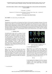
Additionally, the accuracy of exterior orientation elements based on bundle adjustment for the image pairs was estimated. 5000
4000 3000 2000
1000 300~ 300 275 250 225 200 175 150 125 100 75 50 25
0
# of feature points
Figure 7. Distribution of number of feature points
Figure 6. Target example Table 1. Video camera specifications Number of pixels 14,100M [pix] Focal length 4.3 – 68.8 [mm] Image size 1280 x 720 [pix] Frame rates 30 [fps]
4.1 Image Selection of the Proposed Method The image matching was applied to 19,581 image pairs in total. Figure 7 depicts distribution of number of extracted feature points in an image pair. According to the distribution, a threshold of number of feature points to distinguish low quality images was set as 25. When the number of feature points in image pair was less than the threshold, the image pair was removed as low quality images. As a result, 1,354 image pairs were removed. The remaining image pairs (18,227 pairs) were used in next processing.
According to the image pairs after removal of low quality and similar images, image connectivity graph is constructed. The original image connectivity graph had 15,892 edges, which expresses the combination number of images (number of node was 929). Here the original image connectivity graph was divided into 5 subsets (partial graph) for calculation efficiency. Applying graph cuts, the number of edges reduced to 14,731 (number of cut edges was 1,161). Table 2 summarizes changes of the number of edges (the number of the image pairs). The numbers of edges in the image connectivity graph, namely numbers of utilized image combination, were compared between results from the proposed method and ones from original (all images were used). The proposed method decreases the number of edges by about 75% from the original graph. Improvement of the efficiency by the proposed method was confirmed.
original 19,581
Table 2. Summary of number of edges low accuracy similar images graph images removal removal cuts 18,227 15,892 14,731
4.2 Evaluation of Accuracy of the Proposed Method And then, relative orientation for exterior orientation estimation and intersection for 3D reconstruction were applied. To distinguish similar images, threshold of base-height ratio was set. When the base-height ratio was less that the threshold, one of the image pair was removed as similar images. As a result, 70 image pairs were detected and removed. The remaining image pairs (15,892 pairs) were used in next processing.
Results of accuracies by applying bundle adjustment to the selected images and all images were also evaluated. For the evaluation, 3D coordinates of feature points and exterior orientation elements were compared between using selected images and all images. Tables 3 and 4 show a comparison of accuracies of 3D coordinates and exterior orientation elements.
This contribution has been peer-reviewed. doi:10.5194/isprsarchives-XLI-B5-641-2016
645
The International Archives of the Photogrammetry, Remote Sensing and Spatial Information Sciences, Volume XLI-B5, 2016 XXIII ISPRS Congress, 12–19 July 2016, Prague, Czech Republic
Table 3. Comparison of accuracies of 3D coordinates of feature points X Y
X Y Y all images 1.584 -37.019 1.239 selected images 1.226 -35.849 1.324 X , Y , Z : 3D coordinates on average of feature points X , Y , Z : standard deviations of measurement errors of the corresponding 3D coordinates X 36.648 35.793
Z
Table 4. Comparison of accuracies of exterior orientation elements (translations) X Y all images selected images
Z
Z 51.935 50.856
1.945 1.803
Z
TX
T
TY
T
TZ
T
146.054 146.054
6.014 6.268
-137.498 -137.498
6.515 6.79
214.513 214.513
9.021 9.402
X
Y
Z
TX , TY , TZ : translation on average of frames
T , T , T : standard deviations of measurement errors of the corresponding translations X
Y
Z
In the tables 3, X , Y , Z express 3D coordinates on average of feature points, and X , Y , Z standard deviations of measurement errors of the corresponding 3D coordinates, respectively. Also in the table 4, TX , TY , TZ express translation on average of frames, and TX , TY , TZ standard
REFERENCES Agarwal, S., Snavely, N., Simon, I., Seitz, S. M., Szeliski, R., 2009. Building rome in a day. Proceeding of International Conference on Computer Vision, pp.72-79.
deviations of measurement errors of the corresponding translations, respectively.
Atkinson, K. B., 1996. Close Range Photogrammetry and Machine Vision. Whittles Publishing, Latheronwheel, UK.
The proposed method kept accuracies as almost same as ones with original with all images. Through the experiments, the significance of the proposed method was also confirmed. Accordingly, Potential to efficient and accurate 3D measurement was implied.
Bishop, C. M., 2006. Pattern Recognition and Machine Learning. Springer, New York, US.
5. CONCLUSIONS This paper develops an automatic image selection method considering network design for huge amount of images. The proposed method is based on image connectivity graph. The image connectivity graph consists of nodes as images and cost edges as FOD consideration. The image selection is corresponding to reduction of the edges. Graph cuts as combinatorial optimization method is applied for the edge reduction. Through experiments with real data, the proposed method achieves 75% of the number of edges. At the same instance, the accuracy can be kept as one of before applying image selection. Accordingly, efficiency improvement with keeping accuracy is confirmed. As a future work, application of the method to not only sequential images but also various kinds of images such as shared images on the internet. In such cases, interior orientation elements should be introduced. To deal with the additional elements, definition of cost function for the edges will be investigated. In current situation, only estimation accuracy of translation between two images is set as cost function. By introducing estimation accuracies of rotation of camera, 3D coordinates of feature points, and interior orientation elements, it will be expected to represent relationships between images deeply. Furthermore, discussion about relationships between efficiency and accuracy will be required. As a result, applicability of photogrammetry will be more increased.
Busacker, R. G. and Saaty, T. L., 1965. Finite Graphs and Networks: An Introduction with Applications. McGraw-Hill Inc., US. Bay, H., Ess, A., Tuytelaars, T. and Vangool, L., 2008. Speeded-up robust features (SURF). Computer Vision and Image Understanding, 110(3), pp.346-359. Fischler, M. A. and Bolles, R. C., 1981. Random sample consensus: a paradigm for model fitting with applications to image analysis and automated cartography. Communications of the ACM, 24(6), pp.381-395. Hartley, R., 1997. In defense of the eight-point algorithm. IEEE Transactions on Pattern Analysis and Machine Intelligence, 19(6), pp.580-593. Hartley, R. and Zisserman, A., 2004. Multiple View Geometry in Computer Vision. Cambridge University Press, Cambridge, UK. Kanatani, K., 1996. Statistical Optimization for Geometric Computation: Theory and Practice, Elsevier, Amsterdam, Netherlands. Luhmann, T., Robson, S., Kyle, S. and Boehm, J., 2014. Close Range Photogrammetry and 3D Imaging [2nd Edition]. Walter de Gruyter GmbH, Berlin, Germany. Zhang, Z., 2000. A flexible new technique for camera calibration. IEEE Transactions on Pattern Analysis and Machine Intelligence, 22(11), pp.1330-1334.
This contribution has been peer-reviewed. doi:10.5194/isprsarchives-XLI-B5-641-2016
646