November 2002
•
NREL/SR-560-32864
Development of Innovative Distributed Power Interconnection and Control Systems Annual Report December 2000December 2001 W. Liss and M. Dybel Gas Technology Institute Des Plaines, Illinois
R. West and L. Adams Encorp Inc. Windsor, Colorado
National Renewable Energy Laboratory 1617 Cole Boulevard Golden, Colorado 80401-3393 NREL is a U.S. Department of Energy Laboratory Operated by Midwest Research Institute • Battelle • Bechtel Contract No. DE-AC36-99-GO10337
November 2002
•
NREL/SR-560-32864
Development of Innovative Distributed Power Interconnection and Control Systems Annual Report December 2000December 2001 W. Liss and M. Dybel Gas Technology Institute Des Plaines, Illinois
R. West and L. Adams Encorp Inc. Windsor, Colorado NREL Technical Monitor: Thomas Basso Prepared under Subcontract No. ACL-1-30605-04
National Renewable Energy Laboratory 1617 Cole Boulevard Golden, Colorado 80401-3393 NREL is a U.S. Department of Energy Laboratory Operated by Midwest Research Institute • Battelle • Bechtel Contract No. DE-AC36-99-GO10337
NOTICE This report was prepared as an account of work sponsored by an agency of the United States government. Neither the United States government nor any agency thereof, nor any of their employees, makes any warranty, express or implied, or assumes any legal liability or responsibility for the accuracy, completeness, or usefulness of any information, apparatus, product, or process disclosed, or represents that its use would not infringe privately owned rights. Reference herein to any specific commercial product, process, or service by trade name, trademark, manufacturer, or otherwise does not necessarily constitute or imply its endorsement, recommendation, or favoring by the United States government or any agency thereof. The views and opinions of authors expressed herein do not necessarily state or reflect those of the United States government or any agency thereof. Available electronically at http://www.osti.gov/bridge Available for a processing fee to U.S. Department of Energy and its contractors, in paper, from: U.S. Department of Energy Office of Scientific and Technical Information P.O. Box 62 Oak Ridge, TN 37831-0062 phone: 865.576.8401 fax: 865.576.5728 email:
[email protected] Available for sale to the public, in paper, from: U.S. Department of Commerce National Technical Information Service 5285 Port Royal Road Springfield, VA 22161 phone: 800.553.6847 fax: 703.605.6900 email:
[email protected] online ordering: http://www.ntis.gov/ordering.htm
Printed on paper containing at least 50% wastepaper, including 20% postconsumer waste
Preface This annual report covers work performed by the Gas Technology Institute (GTI) and its subtier contractor Encorp Inc. (Encorp) for the period of December 2000 to December 2001 under DOE/NREL contract ACL-1-30605-04 titled “Innovative Distributed Power Grid Interconnection and Control Systems.” The following personnel at GTI have contributed to the technical efforts covered in this report: • • •
William Liss (primary contributor) Karen DePodesta Michele Dybel
The following personnel at Encorp have contributed to the technical efforts covered by this report: • •
Larry Adams Randall West
GTI Disclaimer This report was prepared by Gas Technology Institute (GTI) and Encorp Inc. (Encorp) as an account of work sponsored by the National Renewable Energy Laboratory (NREL) and the United States Department of Energy (DOE). Neither GTI, Encorp, NREL, DOE nor any person acting on behalf of either: a. Makes any warranty or representation, express or implied, with respect to the
accuracy, completeness, or usefulness of the information contained in this report or that the use of any apparatus, method, or process disclosed in this report may not infringe privately owned rights; or b. Assumes any liability with respect to the use of, or for damages resulting from the use
of, any information, apparatus, method, or process disclosed in this report. Encorp, Encorp Intelligence, Encorp Power and Virtual Power Plant are registered trademarks of Encorp, Inc.
i
Executive Summary The objective of this three-year contract is to develop innovative grid interconnection and control systems. This supports the continued advancement of distributed generation in the marketplace by making installations more cost-effective and compatible across the electric power system and energy management systems. Specifically, the overall goals are: •
To develop and demonstrate cost-effective distributed power grid interconnection products and software and communication solutions applicable to improving the economics of a broad range of distributed power systems, including existing, emerging, and other power generation technologies
•
To enhance the features and capabilities of distributed power products to integrate, interact, and provide operational benefits to the electric power system and advanced energy management systems. This includes features and capabilities for participating in resource planning, the provision of ancillary services, and energy management.
These objectives will be undertaken in three phases of a three-year contract with specific tasks as follows: Phase 1 (Base Year): Core Enabling Technology Task 1: Develop Prototype Advanced Controller Task 2: Develop Prototype Power Sensing Board Task 3: Expanded Suite of Communication Capabilities Task 4: Interface for Revenue-Grade Meter Task 5: Demonstrate Interconnect DP Device Phase 2 (Option Year 1): System Level Command and Control Task 6: Type Testing Task 7: System Command and Control Task 8: Demonstration of Controlled DP Resources Phase 3 (Option Year 2) Interoperability and Communications Task 9: Interoperability Systems Analysis Task 10: Demonstration of Grid-DP Interoperability This annual report provides the results of the work completed on the advanced grid interconnection controller in the base year. The design specification work has resulted in the following first-year technical achievements: • •
A prototype design that provides for a 20-fold performance improvement through the use of a high-speed controller central processing unit along with a high-speed digital signal processing chip A prototype design that reduces the controller footprint/volume requirement (40% reduction)
ii
• • • • • • • •
A design that reduces customer installation and maintenance costs with improved packaging involving a simplified strategy for the wiring of terminals and connectors A design that reduces manufacturing costs (a projected 15% to 20% reduction) A prototype design that increases control capabilities with the design of an anti-islanding control scheme A prototype design that increases control capabilities with the design of a loss-ofsynchronization control scheme A prototype design that reduces overall grid interconnect system capital and installation costs with the elimination of additional system hardware now intrinsic to the advanced controller (i.e., improved firmware and communications capabilities) A design that includes anticipated compliance with current and projected industry standards for switchgear and interconnection devices (IEEE P1547 was not released as a standard during the base year) A prototype design that increases functionality available for the distributed power customer A prototype design whose functionality was demonstrated in the Chowchilla case study.
The implementation of later phases of this contract will include reports to document the accomplishments toward meeting all the contract objectives.
iii
Table of Contents Section 1: Introduction ................................................................................................................1 1.1 Background ..........................................................................................................................1 1.2 Distributed Power Problem Statement.................................................................................3 1.3 Interconnection Controller Problem Statement....................................................................3 Section 2: Interconnection Control System Overview..............................................................7 Section 3: Phase 1 Controller Development Results .................................................................9 3.1 Advanced Controller Development ...................................................................................11 3.2 Power Sensing Board Development ..................................................................................13 3.3 Expanded Communication Capabilities Development ......................................................17 3.4 Revenue-Grade Meter Interface .........................................................................................20 3.5 Demonstration of Interconnection DP Device ...................................................................21 3.6 Overall DOE/NREL Distributed Power Program Support ................................................29 Section 4: Phase 1 Conclusions .................................................................................................30 Appendix A: References ..........................................................................................................A-1
iv
Section 1: Introduction 1.1 Background Various industries, companies, and organizations have worked for decades to develop technologies and products to facilitate the growth of the distributed power (DP), or distributed generation (DG),1 industry. Interest in the use of DG and storage has increased substantially over the past five years because of its potential to provide increased reliability and lower the cost of power delivery to the customer, particularly with customer-sited generation. The advent of competition and customer choice in the electric power industry have, in part, been the stimuli for this increased interest. Also contributing to this trend has been the development of small, modular generation technologies such as photovoltaics, microturbines, and fuel cells. As a cornerstone of competition in electric power markets, DP will serve as a key ingredient in the reliability, power quality, security, and environmental friendliness of the electric power system. By supporting customer choice, distributed power may be the long-term foundation of competition in the electric power industry. Although the application of DG and storage can have many benefits, the technologies and operational concepts needed to properly integrate them into the power system must be developed if we are to realize these benefits and avoid negative effects on system reliability and safety. The current power distribution system was not designed to accommodate active generation and storage at the distribution level — and particularly not systems that supply energy to other distribution customers. The technical issues of allowing this type of operation are significant. For example, control architectures that ensure safe and reliable DP operation, and that exploit the potential of DP to provide grid support, will require modernized system-protection design enhancements. This may require large amounts of information fed to advanced, intelligent local controllers that act quickly and operate local distribution areas for both local- and distributionlevel benefits. New system architectures and enabling hardware and software will need to be developed. Electricity regulation, zoning and permitting processes, and business practices that were developed under the old framework — an industry based on central-station generation and the ownership of generation facilities by regulated monopolies — can be barriers to the orderly development of market opportunities for DP in a restructured electric power industry. The system integration issues related to DP are national issues that cut across a number of industries. By bringing together these various parties — hardware manufacturers (photovoltaics, wind, fuel cells, gas turbine, batteries, etc.), utilities, energy service companies, codes and standards organizations, state regulators and legislators, and others — there is a significant opportunity to address the technical, institutional, and regulatory barriers to distributed power. In fact, these very groups are working together on the technology and infrastructure issues.
1
Although no uniform definition applies, distributed power and distributed generation generally refer to small power facilities of 20 MW to 30 MW or smaller.
1
This contract pursues technology development that not only meets the interconnection performance, safety, and operational technical requirements but that also will alleviate infrastructure barriers to DP. Under this contract, enabling hardware, control logic, and communications capabilities will be developed, demonstrated, and validated in conventional and emerging DP technologies and products. Success will result from focusing on key enabling technologies and features built into system-level integrated solutions that work for customers and other stakeholders and participants in the DP market. This will enable market participants to more fully capture and realize the benefits of DP products. GTI's efforts to develop advanced grid interconnection products began in 1985 with benchmarking, surveying electric utilities for technical requirements, and performing distribution-level power system simulation studies. That effort resulted in the first commercial multifunction solid-state protective-relaying package using digital signal processing (DSP) technology. Those efforts included joint testing with electric utilities to address new technology adoption challenges (e.g., the reluctance to shift from "tried and true" conventional electromechanical protection devices to integrated solid-state electronic equipment). Since being introduced, thousands of these multifunction protective-relaying systems have been used in DP system applications. Many companies followed suit with similar products, and electric utility acceptance increased tremendously for the new technology. That effort resulted in millions of dollars of capital, engineering, and maintenance cost savings and helped enable small DP and cogeneration projects to move from concept to reality. As we head into the next decade, there is a critical need to support enabling technology that benefits increasingly smaller and more diverse DP products and that allows for interoperability between the DP source or sink and the grid. Because of the increased competition brought on by utility restructuring, the market will increasingly demand lower costs and more features (i.e., more value) from DP projects. That is essential to increasing the appeal and market acceptance of these systems. The integration of a host of discrete DP generators into state-of-the-art virtual power plants will be a major market achievement. Transparent solutions that can be employed with a diverse array of DP technologies and products will lead this movement. That application space includes: • • • • • • •
Conventional technologies (engines and turbines) using conventional fuels (natural gas and diesel) and unconventional fuels (waste fuels such as landfill gas) Emerging technologies (microturbines and fuel cells) operating on conventional and unconventional fuels Renewable technologies such as wind, solar, and small hydropower systems Small-scale cogeneration or combined heat and power (CHP) applications such as backpressure turbines (BPT) that can be affordably connected at small sizes Enabling the aggregation of DP capacity and energy to provide valuable ancillary services at the distribution and transmission level Enabling command and control strategies essential for the integration of DP into grid operations Energy management systems. 2
1.2 Distributed Power Problem Statement During the course of the past two decades, the independent power industry has thrived in the United States — at least for larger systems. Multimegawatt simple-cycle and combined-cycle gas turbine power systems are the dominant technology choice for new power generation investments because of their favorable attributes of low cost, high efficiency, low emissions, and speed of project construction. In contrast, the market for small-scale power generation has not developed very substantially over this period. There are many causes for the lagging nature of the DP market, including negative scaling effects for small power systems (i.e., higher cost per kilowatt with decreasing size), legitimate technical issues, inadequate product choices, and competitive responses from electric utilities. Examples of electric utility efforts to limit small DP market growth include long approval times and high costs for electric power system interconnection, special incentive rates to prevent customer loss, and high fees for standby power. More examples are contained in “Making Connections: Case Studies of Interconnection Barriers and their Impact on Distributed Power Projects” (NREL/SR200-28053). This National Renewable Energy Laboratory (NREL)/Department of Energy (DOE) report identified a 10-point action plan for addressing barriers to expanded DP use: 1. 2. 3. 4. 5. 6.
Adopt uniform technical standards for interconnection of distributed power to the grid. Adopt testing and certification procedures for interconnection equipment. Accelerate development of distributed power control technology and systems. Adopt standard commercial practices for any required utility review of interconnection. Establish standard business terms for interconnection agreements. Develop tools for utilities to assess the value and impact of distributed power at any point on the grid. 7. Develop new regulatory principles compatible with distributed power choices in both competitive and utility markets. 8. Adopt regulatory tariffs and utility incentives to fit the new distributed generation model. 9. Establish expedited dispute resolution processes for distributed generation project proposals. 10. Define the conditions necessary for a right to interconnect. Through NREL, DOE took steps to address these and other barriers to DP market growth through RD&D initiatives. An NREL three-year competitive solicitation requiring cost sharing was won by GTI and Encorp to address technical development activities directly in support of action items 1 through 3 above. The result of the first year of contract work toward these objectives is the subject of this report. Other parallel DOE/NREL efforts are under way to address these and other action items. These efforts hold significant promise for reducing the barriers to DG and CHP system use in the United States. 1.3 Interconnection Controller Problem Statement As noted, many existing and emerging DP technologies suffer from relatively high total installed costs (in dollars per kilowatt). This is due in part to physical costs for interconnection equipment
3
(e.g., switchgear, protective relays, and controls) as well as high “transaction costs” of working with utilities and other parties to permit equipment for grid interconnection. These costs can escalate as the functionality of a DP installation strives to meet higher-level objectives such as integrating and interacting with the electric power system (and its supervisory control systems) or with building energy management systems. In many instances, the small size of DP systems makes it difficult to justify the added cost for networking and customizing a product to a particular application. In addition, the small scale of many DP project places them below de minimis size limits that distribution or transmission operators deem worthy of consideration. These factors make it difficult for small DP systems to provide value-added benefits to the electric power system (at least benefits that are monetized). This situation negatively affects the economic value of DP technologies — even though their aggregate capabilities have the potential to offer real benefits to the grid. The DP industry also faces loss in value because of the inability of various products to work together. Lack of cross-platform compatibility exists among products ranging from turbines to engines, steam turbines, microturbines, fuel cells, wind turbines, photovoltaic systems, power quality systems (batteries and flywheels), and heat-recovery devices. This means that system integrators miss the potential for pooling resources in a manner similar to the virtual power plant concept (where a number of smaller generators can be networked together and controlled to provide the equivalent of a multimegawatt power plant or load center). A system integrator that can pool resources will be better positioned to provide valued services that will earn an economic return. Encorp Inc. was founded in 1993 to serve the energy automation needs of the energy industry and its customers as deregulation began transforming the electric utility industry. Encorp's innovative Encorp Power control systems and Virtual Power Plant™ software were introduced to greatly simplify the task of managing and controlling a large number and wide variety of distributed resources — including engine generator sets, microturbines, fuel cells, wind turbines, and energy storage devices. Encorp remains committed to serving the needs of the growing DP industry. The current Encorp Power Generator Power Control (GPC) with the Power Transfer Controlenabled configuration provides safe, reliable transfer of power between a single generator and the utility grid. Standard options include a wide variety of traditional control modules and opencommunication protocols integrated into a single unit. The Encorp GPC with the Kilowatt Sharing-enabled configuration provides reliable paralleling of multiple generators. Combined with the Encorp Utility Power Control (UPC), the Kilowatt Sharing-enabled GPC provides synchronizing and paralleling of multiple generators to the utility grid. Although these products provide satisfactory features and value to customers today, a number of additional desirable features and functionalities are not resident in the existing GPC or competitor products. R&D efforts are needed to provide greater functional integration, switchgear design simplicity, and cost reduction for the customer. Example needs include features to meet advanced communications, diagnostics, monitoring, and relay function expectations of customers as well as to ensure compliance with anticipated future interconnection standards within IEEE P1547.
4
A primary motivation for the IEEE P1547 standard is the desire of many market participants to rationalize and simplify the process for interconnecting a DP device with the electric power system. The following figure illustrates a typical interconnection scheme for a DP device with a generation source (labeled GS in Figure 1) supplying power at a customer site. In many instances, the generation source is sized to meet a portion of the customer’s peak power needs. Electricity is often not exported in this type of arrangement, but it could be in some instances. The generation source may also be used to provide emergency power in the event of loss of electric service. Utility Distribution Line
Legend
Substation Transformer
Shaded Region: Basic Requirements for Interconnection
Site Load Visible Disconnect Switch
27/ 59
81 O/U
PT
32
Required Interconnection E i * 25 Synchronizing 27/59 Under/Over Voltage 81O/U Over/Under Frequency -Visible disconnect -Potential, Current (as needed). Suggested Operational I * (not required) 32 Directional Power -VAR Controller. Adjustable for synchronous
* List will vary by site.
CT VAR Controller Circuit Breaker
PT 25
GS Figure 1: Typical interconnection of DP
The IEEE P1547 standard is intended to be a performance-based document rather than a prescriptive document that lays out specific relay functions that must be incorporated into a device. This approach is in line with the evolution of the market during the past decade from discrete electromechanical relay devices toward integrated multifunctional, microprocessor-based interconnection and control systems that can perform a number of operations through control algorithms. With the move toward performance-based standards, however, there is a desire to enable DP controller devices with higher-level functionality and safety features. For example, a concern among utilities is what happens to a DP generation source when a fault occurs on the utility distribution line (or electric power system). If a utility line breaker is open because of a temporary fault and subsequently reclosed, the DP device may inadvertently continue operating and be out of phase when the primary source is restored. In a worst-case scenario, a DP
5
generation source may inadvertently supply power to a line that a service person thought was not energized. These types of scenarios are raising expectations that DP products will provide higher levels of processing performance and control sophistication to address a range of issues that goes beyond conventional over and under voltage and frequency detection. A key element of this project is the development of a high-performance computing platform that will allow high-speed monitoring and detection of system fault conditions and use of sophisticated algorithms that can address the host of potential application requirements for interconnecting a DP source into electric power systems.
6
Section 2: Interconnection Control System Overview To address the technical and market needs of the evolving DP market, GTI and Encorp identified a multiyear plan. This effort begins with the development of a new and significantly enhanced core controller technology and evolves into the development and demonstration of higher-level controls, software, communications capability, and functionality that captures the objective of improving the DP value proposition. In parallel, this plan is intended to support the development of interconnection and DP communication standards — notably, the IEEE P1547 standard. Table 1 shows the three phases of the contract with each of the individual tasks. Phase 1, the core enabling controller technology development phase, addresses the specifications for grid interconnection and controller architecture for DP equipment. This design and specification activity encompasses the core controller electronics and software, multiphase voltage and current power sensing board, communications hardware and software, and an interface suitable to tie in with a KYZ-compatible revenue meter (while also providing revenue-grade direct meter measurement capability). Table 1: Contract Phases and Tasks Phase 1 (Base Year): Core Enabling Technology Task 1: Develop Prototype Advanced Controller Task 2: Develop Prototype Power Sensing Board Task 3: Expanded Suite of Communication Capabilities Task 4: Interface for Revenue-Grade Meter Task 5: Demonstrate Interconnect DP Device Phase 2 (Option Year 1): System Level Command and Control Task 6: Type Testing Task 7: System Command and Control Task 8: Demonstration of Controlled DP Phase 3 (Option Year 2) Interoperability and Communications Task 9: Interoperability Systems Analysis Task 10: Demonstration of Grid-DP Interoperability
Phase 2 and Phase 3 of the contract address important topics related to type testing and verification of compliance with current and projected industry standards (in particular, IEEE P1547). In addition, progressive software development is planned to demonstrate the capability of the controller to provide system-level command and control functionality as well as system interoperability. This is envisioned to provide an increasing level of communication and control interaction among an array of value-chain participants and devices, including: • • • • • •
DP equipment (e.g., engines) Energy management systems DP equipment operators and aggregators DP equipment operations and maintenance companies Energy management and energy service companies Electric distribution utilities and ISO/RTO organizations.
7
In addition to conducting the technical tasks identified in Phase I during the base year, there were concurrent efforts in the development of interconnection standards through the IEEE P1547 working group and participation in several DOE Distributed Power Program (DPP) review meetings.
8
Section 3: Phase 1 Controller Development Results During the course of the Phase I (base year) contract, the following tasks were identified: • • • • •
Task 1: Develop prototype advanced controller Task 2: Develop prototype power sensing board Task 3: Expand suite of communication capabilities Task 4: Develop interface for revenue-grade meter Task 5: Demonstrate interconnect DP device.
The following subsections, 3.1 through 3.5, provide details of the technical results of this work as they correspond to tasks 1 through 5, respectively. The following overview of the design specification phase for the advanced controller summarizes notable technical achievements and their associated economic advantages in five key areas: • • • • •
Hardware Firmware Software Communications Packaging.
Hardware. The primary hardware concept will achieve both technical and economic advancements by providing a modular system that can easily be expanded but that has a low cost for basic system configurations. The hardware design features two standard modules and optional modules and boards and includes the following: •
Prototype base controller design, firmware, and function block software o Prototype controller module design − One central processing unit (CPU PCA) − One standard input/output and power supply (SIO PCA) − One LED PCA − Mechanical enclosure − Firmware o Prototype power sensor module design (Phase 1 power supply can supply up to 5 PSM per controller module) − One power sensor module (PSM PCA) − One LED PCA − Mechanical enclosure − Firmware o Function block software
9
•
Prototype base controller design expansions/options and firmware o Controller module (options) − Mezzanine expansion option (Qty 2 – M Modules) − Auxiliary PCA options (implementation of custom applications – Elecktryon, OEMs, etc.) − Firmware
Firmware. The firmware functions and features will offer compliance with pertinent industry standards, improvements in controller installation, and elimination of additional applications, thus reducing capital and installation costs. The prototype advanced controller design includes: • • • •
•
Protective relay functions required by IEEE P1547 Standard utility-grade relay models for protective relay functions Alarming, data logging, trending, and other functions Prioritizing of resources for processor updates: o Critical code (i.e., protective relay models) located in an event-driven resource to be run immediately upon update of voltage, current, and power values o Less critical functions (i.e., kW and VAR controls) grouped in a separate resource to be run periodically o Configuration values grouped together in another resource that need only be run on initialization at power up or when a configuration change is made. Several installation and configuration support improvements, including remote firmware upgrades, high-speed downloads of firmware and configurations.
Software. The prototype advanced controller design includes an upgraded software platform that streamlines the system tools while removing limitations that complicated their implementation, thus saving on installation costs and time. The prototype advanced controller design improves the software and programming environment through: • • •
Software tools with expanded ability to handle complex as well as simple distributed objects A reduction from two systems to design and configure controls and control systems to a single system A reduction in several software logic objects and 24 virtual I/O cards.
Communications. The prototype advanced controller design allows expanded communications capabilities with both higher- and lower-level devices, eliminating the need for additional external hardware and its associated capital and installation costs. The prototype advanced controller design improves communications capabilities and includes interfaces with the following device types: 10
• •
Higher-level systems for uses such as monitoring, display and analysis, remote dispatch, metering, billing, and alarming Lower-level devices for low-cost I/O, displays, and other OEM controllers.
Packaging. The prototype advanced controller design offers improved assembly and maintenance features intended to reduce typical installation and maintenance time and costs. Hardware assembly will be packaged to allow: • •
Wiring and cabling to be performed without removing the top cover LEDs visible from the top of the controller and power sensor modules without removing the top cover.
Summary. The design specification phase resulted in several notable technical advancements that, along with other product features, will help meet the contract objectives of providing increased DP value proposition by lowering total costs for interconnection while simultaneously providing added features and performance. This will be done while meeting pertinent industry standards. The prototype advanced controller design has the following performance metric projections: • • • • • • • • •
Twenty-fold performance improvement through the use of a high-speed controller CPU along with a high-speed DSP chip Reduced controller footprint/volume requirement (40% reduction) Reduced customer installation and maintenance costs with improved packaging involving a simplified strategy for wiring of terminals and connectors Reduced manufacturing costs (15% to 20% reduction) Increased control capabilities with the development of an anti-islanding control scheme Increased control capabilities with the development of a loss-of-synchronization control scheme Reduced overall grid interconnect system capital and installation costs with the elimination of additional system hardware now intrinsic to the advanced controller (i.e., improved firmware and communications capabilities) Anticipated compliance with current and projected industry standards for switchgear and interconnection devices Increased functionality available for the DP customer.
3.1 Advanced Controller Development The controller module is the repository for firmware that coordinates the logic, features, functions, programmability, adaptability, and versatility of the Encorp GPCs. To provide price point and feature flexibility, the controller is designed to provide flexibility and expandability to meet the needs of both small and large DP equipment. The minimum configuration of the
11
prototype controller module design contains a CPU, LED display, and SIO printed circuit assemblies (PCAs). Additional optional items are also available. The CPU PCA is the main processing element and communications hub. The CPU board incorporates a high-performance but cost-effective processor operating at sufficiently high processing speed to support the growing processing demands of DP applications and increased communications capabilities. The CPU board includes extensive memory support — including the capability for storage expansion to support features such as data logging and trending. The processor section of the CPU board will have extensive communications capabilities required by future applications. This includes capabilities such as supporting LonWorks, 100 Base-TX Ethernet, Controller Area Networks (CAN) interfaces, RS-232/485, and Modbus communications. The controller is designed with flexibility to handle a variety of other expanded communications capabilities; these will be incorporated in future development efforts tied to development and demonstration of expanded control and communication features. More discussion of advanced communications is contained in Section 3.3. The data storage specification is based on a preliminary assessment of the requirements. The controller will support the following memory configurations: • • • •
Flash memory Static random access memory (SRAM) Nonvolatile random access memory (NV-RAM) Removable/expandable memory cards.
The flexibility in the design of the memory will allow the controller to be expandable or extendable to meet a variety of product features and applications. The controller will have a watchdog timer and real-time clock. The real-time clock will support at least the following minimum features: • • • • •
Year 2000 (Y2K) compliance Totally nonvolatile for more than 10 years of operation in the absence of power Provide year, month, date, day, hours, minutes, and seconds Automatic leap year compensation valid up to the year 2100 Accuracy to within one minute per month at 25°C.
The CPU board design has various connectors for I/O — each able to handle multiple channels. These connectors will address various analog, digital, and time processor unit (TPU) channels, queued serial peripheral interface (QSPI) signals, power supply sources, and other functions. Among the variety of I/O functions is the ability to handle several pulse inputs to interface to legacy revenue-grade meters. Each pulse input will meet the following requirements:
12
• • • •
Two-wire connection with external wiring of the supply voltage Wide input voltage capability Termination of any 12- to 24-AWG wire Ability to count input pulse rates of 50 pulses per second minimum.
The controller design supports analog kilowatt-sharing lines compatible with the current Encorp control, which will provide backward kilowatt-sharing compatibility. The analog kilowattsharing lines shall be independent of all other inputs and outputs on the controller. With respect to interconnection, the prototype advanced controller design incorporates (among other features) the following functions: • • • • • • • • •
Sync check (25) Autosynchronizer (25 A) with voltage matching, two modes available: frequency and phase matching and slip frequency. High-speed (160 msec) over/under voltage for generator and utility tie (27/59) High-speed (160 msec) over/under frequency for generator and utility tie (81 O/U) Directional power (32) Directional reactive power (32 VAR) Reverse-phase/phase-balance current (46) Phase sequence voltage (47) Voltage-restrained over current (51 VR)
•
AC time over current (51 N)
• • •
Anti-islanding relay Loss of synchronization relay (required for applications with stiffness ratio of 20 or less) Over-current relay (required for over 2-MVA units) Form-C contact outputs Harmonic distortion alarm.
•
•
Other capabilities (e.g., additional relay functions) can be incorporated into the controller. 3.2 Power Sensing Board Development The power sensor module (PSM) design is a stand-alone intelligent module powered by highpower DSP technology. The primary purpose of this module is to interface with multiphase voltage (potential) and current transformer (PT and CT) inputs. This module will perform extensive signal processing and management of the input information and transfer the resulting values to the controller module. This encompasses various electric power issues related to real and reactive power as well as harmonics. In addition, this module contains relay outputs for circuit breaker close/open control, digital inputs for auxiliary contact feedback, and solid-state digital outputs for relay targets or secondary circuit breaker control.
13
The prototype PSM module design has sufficient memory to allow up to 64 cycles of waveform information to be buffered to support an event-reporting application. In addition, the power sensor module software will perform several high-speed protective relay functions (e.g., over/under voltage [27/59], over/under frequency [81 O/U], sync check [25], and loss of synchronism relay [78]). The following parameters will be measured and provided by the PSM design on all four phases: Voltage RMS
V, selectable L-N or L-L
Current RMS
A
Watts RMS
P
True Power Factor
PF
VA RMS
S=V*A
VAR RMS
Q
Displacement PF
DPF
Fundamental W
P1
Fundamental VA
S1
Fundamental VAR
Q1
Voltage phase angle
Radians, relative to DFT window
Voltage harmonics
32nd, on demand
Current harmonics
32nd, on demand
Voltage total harmonic distortion
V THD
Voltage total odd harmonic distortion
V TOD
Voltage total even harmonic distortion
V TED
Current total harmonic distortion
I THD
Current total odd harmonic distortion
I TOD
Current total even harmonic distortion
I TED
14
The following parameters are provided by the PSM design on three phases: Equivalent system voltage
Ve = √ (Va² + Vb² + Vc²) / 3
Equivalent system current
Ie = √ (Ia² + Ib² + Ic²) / 3
Total W
Pt = Pa + Pb + Pc
System VA
Se = 3 * Ve * Ie
Total VAR
Qt = Qa + Qb + Qc
Total true PF
PFt = Pt / Se
Total fundamental W
P1t = P1a + P1b + P1c
Total fundamental VA
S1t = S1a + S1b + S1c
Total fundamental VAR
Qt1 = Q1a + Q1b + Q1c
Total displacement PF
dPFt = P1t / S1t
Negative sequence voltage
V2a = 1/3 (Va + a*Vb + a²*Vc), where a* is the 120 degree vector operator and a²* is the 240 degree vector operator.
Positive sequence voltage
V1a = 1/3 (Va + a²*Vb + a*Vc)
Zero sequence voltage
V0a = 1/3 (Va + Vb + Vc)
Voltage sequence imbalance
V2a / V1a
Negative sequence current
I2a = 1/3 (Ia + a*Ib +a²*Ic)
Positive sequence current
I1a = 1/3 (Ia + a²*Ib +a*Ic)
Zero sequence current
I0a = 1/3 (Ia + Ib + Ic)
Current sequence imbalance
I2a / I1a
The PSM design has several digital and relay outputs. These will enable control of external lamps and relays — including the ability to actuate high-current relays. This will be done while ensuring compliance with industry-recognized high-voltage isolation capability.
15
The PSM board design contains various PT inputs with the following properties: • • •
Nominal 120 V AC with a range of 40 V AC to 150 V AC Accuracy of ±0.25% over temperature and time Maximum 0.2 VA burden at 120 V.
The PSM board design contains CT inputs with the following properties: • • • • •
Nominal 5 A with a maximum of 7 A Withstand 20-A continuous current Withstand 300-A transient current for 1 second Accuracy of ±0.25% over temperature and time Maximum 0.2 VA burden at 5 A.
The IEEE P1547 draft standard establishes criteria and requirements for interconnecting distributed resources with electric power systems (EPSs). Protective relay functions are planned to comply with all requirements of this standard. The PSM design performs a minimum set of critical high-speed protective relay functions including: • • • •
Under voltage/over voltage relay (three phase/one phase) (27/59) Frequency relay (81 O/U) Out-of-step protective relay (78) Synchronism check device (25).
Other functions can be incorporated, as needed, within the PSM or controller module. The specification for each function follows: Under Voltage/Over Voltage Relay (Three Phase/One Phase) (27/59) The U/O voltage protection function will measure the effective (RMS) or fundamental frequency value of each phase-to-neutral or, alternatively, each phase-to-phase voltage. When the measured voltage is less than a minimum percentage set point or greater than a maximum percentage set point of base voltage (nominally 120 V), the PSM will issue a breaker open command through one of the high-speed relay outputs. These set points shall be adjustable to a minimum range of 50% to 120% of base voltage. The maximum time from the start of the abnormal condition to the relay contact output will be 48 ms. Clearing time is the time between the start of the abnormal condition and the DP ceasing to energize the Area EPS. Note that this time includes any delay in the circuit breaker or other interconnect device, so clearing-time adjustments must account for this delay — placing further emphasis on the need for high-speed detection and recognition. The voltage and clearing time set points will be field adjustable so an operator can specify different voltage settings or trip times to accommodate system requirements. Field-adjustable settings will be protected against unauthorized adjustment.
16
Frequency Relay (81 O/U) The PSM will follow the interconnected Area EPS frequency within the range 59.3 Hz to 60.5 Hz (on a 60-Hz base). At a minimum, the over/under frequency (81 O/U) protective relay will be adjustable between 57 Hz and 60.5 Hz. The maximum time from the start of the abnormal condition to the relay contact output will be 48 ms. Clearing time is the time between the start of the abnormal condition and the DP ceasing to energize the Area EPS. Note that this time includes any delay in the circuit breaker or other interconnect device, so clearing time adjustments must account for this delay. The frequency and clearing time set points will be field adjustable so an operator can specify different frequency settings or trip times to accommodate system requirements. Field-adjustable settings will be protected against unauthorized adjustment. Out-Of-Step Protective Relay (78) Synchronous generators in applications with a stiffness ratio of 20 or less will be equipped with loss of synchronism (out-of-step) protective functions to isolate the DP from the Area EPS without any intentional time delay. The solution to be implemented is described in a Redfern and Checksfield IEEE Transactions paper (see Appendix A). Synchronism Check Device (25) The sync check device shall be adjustable to the following: • • •
Frequency difference (∆f, Hz), minimum of 0.1 Hz [Target +/- 0.01 Hz] Voltage difference (∆V, %), minimum of 3% of the base voltage [Target +/- 0.25%] Phase angle difference (∆∅,°), minimum of 10% [Target +/- 1 degree].
3.3 Expanded Communication Capabilities Development2 A critically important element of this development effort is the incorporation of an expanded set of communication capabilities. This includes communication pathways to tie into existing and future energy management systems, electric utility command and control centers, independent system operator (ISO) and regional transmission operator (RTO) organizations, and other participants. Communication technology is seen as an essential element of the long-term DG value proposition. With regulatory and legislative changes transforming the electric power industry from a monopolistic to a deregulated and competitive industry, there is increasing need for information and data exchange among open systems and interoperability across multivendors’ hardware. An example of the type of information exchange is contained in a key American Society of Heating, Refrigerating, and Air-Conditioning Engineers Inc. (ASHRAE) report produced by Martin Burns and Michael Kintner-Meyer. They identified the following as key communication information services:
2
Information is Section 3.3. is based on input provided by M. Burns, based on the referenced ASHRAE report.
17
1. 2. 3. 4. 5. 6. 7. 8. 9.
Revenue meter reading (electricity, gas, water, steam) Quality of service monitoring Real-time-pricing transmission Load management service On-site generation supervisory control Energy-efficiency monitoring Weather reporting and forecasting services Indoor air-quality monitoring Dynamic demand bidding into a power exchange.
What is significant about these findings is that nearly all, with the exception of Item 8, relate directly to aspects of the value proposition possible with DG and advanced controllers. 3.3.1. Evolution of Communications Standards The primary goal of communications standards is interoperability. Communications standards evolved primarily in the 1970s and 1980s. Because of the “topology” of various communication methods, many specialized communications protocols were developed for different application domains. In fact, in the 1990s, virtually every technical domain was represented by its own communications standards effort. The result was a cornucopia of standards that were “domainspecific.” That is, the communications standards, besides providing for the generic goal of exchanging information, contained semantics and architectural elements that recognized specific industry requirements. An example of this is DNP, which recognized the “freezing” of data measurements in its communications services model. The advent of wide area network (WAN) connections to local area networks (LANs) introduced a new obstacle to interoperability. That is, the scope of applications evolved to overlap domains. The following figure illustrates the relative complexity (and therefore implicitly, relative cost) versus the capability of several application layers in communications protocols. The protocols shown in the figure are all suitable for interoperable exchange of measurement and control information such as a switch position (i.e., on/off).
18
Figure 2: Relative complexity and capability of communication standards (Burns, et al)
Key: BACnet CAN CEBus COM+ CORBA DNP Fieldbus/Profibus LONWorks PEEK/POKE PSEM SNMP UCA/CASM
ANSI/ASHRAE 135 protocol for Building Automation and Control Networks Control Automation Network Electronic Industry Associations Consumer Electronic Bus, EIA 600 Microsoft Distributed Object Model Object Management Group Distributed Object Model Distributed Network Protocol Industrial control network Echelon’s Local Operating Node communications protocol Metaphor for "Basic programming language" memory manipulation instructions Protocol for Electric Meters, ANSI C12.18, ANSI C12.19 Internet Engineering Task Force’s Simple Network Management Protocol RFC 1156/ RFC1157 EPRI Utilities Communication Architecture Common Application Services
3.3.2. Implications of Communication Standards Situation Given the complexity of the communications landscape, it is imperative for the new controller design to incorporate sufficient capability and flexibility to accommodate historic communication protocols and practices as well as evolving developments (in terms of standards, devices, and methods). A number of communications capabilities have been identified that would allow the controller to interface with higher-level systems for uses such as monitoring, display and analysis, remote
19
dispatch, metering, billing, and alarming. Expanded communication capabilities are also desired for interface with other low-level devices for low-cost I/O, displays, and other OEM controllers. Features included in the controller to support communications include: • • • •
100 Base-TX Ethernet with TCP/IP stack for high-level, high-speed communications CAN/DeviceNet (2 channels) for low-level, high-speed communications LonWorks for low-level, long distance communication RS-232/485 (2 channels) for serial communications (Modbus will use one of these channels).
TCP/IP networking support will be provided with the RTCXnet network communication suite. The network communication suite is fully integrated with the RTXC kernel. The networking support will include TCP/IP, UDP, Address Resolution Protocol (ARP), Internet Control Message Protocol (ICMP), Domain Naming System (DNS) client, Dynamic Host Configuration Protocol (DHCP) client, Telnet, and Point-to-Point Protocol (PPP). 3.4 Revenue-Grade Meter Interface The specification of the controller includes the ability to interface with existing (or “legacy”) electricity meter devices as well as the ability to provide stand-alone revenue-grade meter information. Aspects of the metering capability were also covered in Section 3.2. With respect to interfacing with existing meters, the intent is initially to incorporate features common to the most widely used electric demand meters. Electric demand meters can include, or be modified to include, a pulse output. This is often done using what is referred to as a Form C relay, also known as a KYZ relay. In this nomenclature, the K is usually the common of a singlepole, double-throw (SPDT) relay, the Y contact is normally open, and the Z contact is normally closed. The relay device changes state between open and closed with each rotation (or partial rotation) of the meter disk. The KYZ output is also referred to as a pulse meter. With input on various factors associated with the meter device, the KYZ output can be used to provide revenuegrade information on power and energy usage. The meter design specification incorporates the ability to interface with KYZ-based meter signals. In addition, the PSM design of the new controller will be required to have revenue-grade metering capabilities. The controller is designed and will be tested to the power and energy accuracy requirements of ANSI C12.20-1998, Accuracy Class 0.5. The accuracy will be internally tested or verified by a third-party laboratory. Additional background information is also contained in ANSI C12.19.
20
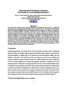
3.5 Demonstration of Interconnection DP Device To document the first-hand market issues with the interconnection and communications of DP systems, a system case study was done on the Chowchilla II (Chow II) power generation station in Chowchilla, Calif. Encorp Inc. designed the controls and switchgear system for this complicated plant. The implementation of Chow II is a prototype version of some of the features and functions that would be implemented on the production version of the advanced California ISO controller being developed. This prototype From the CAISO Web site (www.caiso.com): California ISO is charged with managing the flow of hardware is not integrated in the same electricity along the long-distance, high-voltage manner as planned on the advanced power lines that make up the bulk of California’s controller but serves as a model for the transmission system. The not-for-profit public-benefit corporation assumed the responsibility in March capabilities that would be integrated into the 1998, when California opened its energy markets to advanced controller. competition and the state’s investor-owned utilities turned their private transmission power lines over to the California ISO to manage. The mission of the California ISO is to safeguard the reliable delivery of electricity, facilitate markets, and ensure equal access to a 12,500-circuit mile “electron highway.”
3.5.1. System Overview The Chowchilla II power plant is a 25-MW facility powered by 16 Duetz natural gasfueled generator sets operating in parallel with the local utility.
NRG Energy From the NRG Web site (www.nrgenergy.com): NRG Energy Inc. is one of the world's leading competitive energy providers. NRG has the competitive energy industry's most diverse generation portfolio, distinguished by its range in geography, fuel source, and dispatch level. NRG is on track to increase its megawatt ownership to 50,000 to 75,000 MW by year-end 2005 — a growth rate of at least 25% per year.
The plant is owned by NRG Energy and operated by NEO, a subsidiary of NRG Energy. The power facility, although located in California, is dispatched by NRG from offices in Minneapolis, Minn. The plant is dispatched based on receiving a call from PG&E or in response to area energy pricing signals. The California ISO monitors the facility to determine capacity effect and demand scheduling.
Founded in 1989, NRG develops, acquires, and manages a variety of energy-related operations worldwide. Operations include competitive energy production and cogeneration facilities, power marketing, thermal energy production and transmission, and resource recovery facilities. NRG has a global portfolio of projects in North America, Europe, Asia-Pacific, and Latin America. Our projects use such diverse fuel sources as fossil fuels (natural gas, oil, coal, and coal seam methane), greenpower renewable fuels (biomass, landfill gas, hydro, and geothermal energy), and refuse-derived fuels. As of November 2001, NRG has net ownership interest in approximately 78 projects (223 facilities) in operation and under construction, representing approximately 24,352 MW of capacity. In addition, NRG has signed acquisition agreements for projects totaling 5,036 MW of net equity ownership as well as 9,436 MW in advanced development.
Individual generator power measurements are made by the Encorp GPCs in the system. The power data is gathered and ultimately passed up to the communications processing modules (CPMs) in each system and sent to NRG and the California ISO for their use. Figure 3 illustrates a typical two-engine pair located in the plant. In total, the facility has 16 natural-gas engines.
21
Figure 3: Typical Chowchilla II two-engine configuration
As noted previously, the interconnection requirements for DP vary widely and typically entail more sophisticated and extensive protective relaying strategies for larger systems. Figure 4 illustrates the protective relaying scheme used in this application.
Figure 4: Chowchilla II protective relaying scheme
22
The Encorp communications system at the Chowchilla power generation facility brings together various software, system, and network topologies. As a result of this effort, the following results are realized: •
On-Site Generation Supervisory Control Supervisory control of the on-site generation is provided by the Encorp UPC/GPC controls and the local or remote desktop workstation (DWS). Supervisory control includes remote/local system dispatch, alarm monitoring and trending, event trending, dial out alarm notification, local/remote generator power level settings, and system power-level monitoring.
•
Generator Status/System Status Monitoring The Encorp controls allow local and remote monitoring of a multitude of generator and system data points. These points include: o o o o o o o o o o o o o o
Inlet/Exhaust temperature Coolant temperature Crank case pressure Starting air pressure Lube oil pressure (before and after filter) Lube oil level Supply voltage Throttle position Engine speed (RPM) Generator bearing temps Generator winding temps Generator inlet/outlet air temps Combustion chamber temperatures Gas valve positions.
•
Load Management Service Because this site is used exclusively for supplementing the existing distribution capacity, load management is limited to the ability to adjust the base load reference of the individual generators from a local or remote location via the DWS. Generator power limits and active demand levels are also available at the local or remote DWS.
•
Indoor Air Quality Monitoring Indoor air temperatures are measured and ventilation fans are operated automatically from the Encorp UPCs based on the air temperature of the facility.
•
Revenue Meter Reading This site did not incorporate revenue meter reading in the Encorp system. Revenue meter reading was integrated into the ISO DPG hardware. However, the Encorp system is fully capable of receiving either real or pulse (KYZ) meter information and displaying the resultant demand information from those sources.
23
•
Energy-Efficiency Monitoring The Chowchilla power station did not require energy-efficiency monitoring. If, at some point in the future, the need for efficiency monitoring (heat rate versus kilowatt-hours) is needed, the Encorp software could be easily modified to provide such information.
•
Weather Reporting and Forecasting Services There were no requirements for weather reporting or forecasting services data or I/O for the operation of the Chowchilla project.
•
California ISO Data Numerous monitoring and control points are sent from the Encorp communications system to the California ISO via the DPG. A listing of all these points can be found in the California ISO DPG Technical Specifications via their Web site at www.caiso.com.
3.5.2. System Topology The SCADA system at the Chowchilla power generation station is representative of Encorp’s ability to design, configure, and implement complex communications schemes with distributed controls from numerous vendors. The advanced controller will enable work with a broader array of communication systems. Each engine generator set has two points of data acquisition: (1) the Duetz TEM control, which monitors and controls engine parameters, and (2) the Encorp GPC-KWS control, which monitors and controls generator parameters. The GPC also provides protective relay functions for the generators. The overall system power is monitored and controlled by two Encorp Utility Power Controllers (UPCs). System operating parameters are monitored and controlled by two PLC Direct (Koyo) PLCs. House power is monitored and the house power breaker is controlled by an Encorp MMC. Because of RS232 data loading concerns at the serial hubs, the data acquisition system is divided in half. Eight engine generator sets are served by each PLC, CPM, and DWS. The data is then gathered by each CPM and distributed via Ethernet to the Frame Relay and DPG for access by NEO and ISO. Hewlett Packard ProCurve network switches are used to switch Ethernet communications between the Koyo PLCs, DWSs, Frame Relay, and the CPMs. The TEM controls communicate via TTY current loop into a RS232 serial converter. The engine information is fed into a Rocket Port serial hub, which can handle up to eight RS232 serial inputs simultaneously. The serial hub interfaces with the native Windows COM ports via Ethernet TCP/IP connection. The Encorp GPC-KWS and UPC controls communicate via Echelon LonWorks network to the Lon SLTA PCI card located in the CPM. They also communicate via RS232 port at 19.2 Kbps with a local four-line VFD display.
24
The Encorp MMC controls the house power breaker. The MMC provides house power metering information. Communications to the MMC will be through the LonWorks OPC Server that resides on the CPM. The CPM is an industrial PC operating on a Windows NT platform. Its purpose is to serve as the communications collection point for the various distributed devices in the system. Dial-in capabilities are possible to the CPM via analog line into a 56-K modem. Hewlett Packard ProCurve network switches are used to switch Ethernet communications between the Koyo PLCs, DWSs, Frame Relay, and the CPMs. Local DWSs running Windows NT are used to provide an HMI point for the operators of the system. They communicate with the CPM via Ethernet TCP/IP connection. Dial-out capabilities for the purposes of alarm annunciation via pager are possible through the 56-K modem on the DWS and an analog landline. A SYSCO frame relay is used to provide SCADA to communicate plant information to NRG. The CPM provides data to the frame relay via Ethernet. The frame relay communicates with NRG via leased line provided by MCI Telecommunications. A DPG module serving as the Modbus master polls the CPMs via RS485 serial communications, MODBUS protocol. Data points are sent from the DPG to the California ISO via DNP3.0 protocol over a 56-Kbps modem connection on the DPG. 3.5.3. Software The Encorp Virtual Maintenance Monitor (VMM) software is a graphical user interface (GUI) run on a Delphi application layer. The VMM software usually resides in the CPM but may also be installed in remote terminals that require their own GUI. The VMM uses DCOM clients to access the data provided by the LonWorks network. Custom pages for the VMM are designed by Encorp applications engineers to provide the end-user with useful information regarding the power generation system. Figure 5 shows the generator overview screen that is standard in the Encorp Intelligence VMM GUI.
25
Figure 5: VMM user interface
The Encorp Virtual Power Plant (VPP) server resides in the CPM and is used to provide access to the power generation system configuration and operating information. The number of units, capacity, status, and aggregate load information is available through the VPP server. A remote DWS running the VPP dispatch application is then used to poll the VPP server and issue dispatch commands to the site. A software interface is used to design graphic displays for various discrete, integer, and real data. The following — Figure 6, Figure 7, Figure 8, and Figure 9 — illustrate various user interfaces for this application.
26
Figure 6: Example one-line diagram
Figure 7: Generator room display
27
Figure 8: Generator annunciator display
Figure 9: Generator metering screen
28
3.6 Overall DOE/NREL Distributed Power Program Support In addition to the work outlined in the above tasks, the team of GTI and Encorp participated in several complementary R&D and standards development activities during the base year. These included: • • •
Participation in DOE DPP quarterly review meetings Participation in several DOE/NREL-led IEEE P1547 meetings Participation in the DOE Communications and Control Technology Roadmap Workshop (September 2001).
Although not included in the original base year contract, significant effort was expended in support of activities related to Task 6 – Type Testing. This included the development of a 74page report covering the controller system test plan as well as a 56-page work sheet for guiding engineering and manufacturing personnel in carrying out the testing of the new controller.
29
Section 4: Phase 1 Conclusions The results of tasks 1-5 during Phase I point to the potential of a new controller design to provide significantly enhanced value for the interconnection and interoperability of single and multiple dispersed DG products. This effort has resulted in an advanced controller design that: • • • • • • • •
Provides 20 times the performance of the existing Encorp Power control unit Can be packaged into a space requirement that is 40% less than the existing Encorp Power control unit Provides a meaningful reduction in manufacturing costs Can be packaged into an interconnection and switchgear package at lower cost Can result in a substantially reduced installed cost to the consumer as a result of improvements in the expected packaging of the controller and its connections Results in the provision of a greatly expanded array of functions for the DP customer Should be capable of meeting current and projected industry standards for switchgear and interconnection devices Incorporates new control logic to address anti-islanding and loss of synchronization.
30
Appendix A: References Alderfer, R. Brent; et al. “Making Connections: Case Studies of Interconnection Barriers and their Impact on Distributed Power Projects.” NREL/SR-200-28053. Golden, CO: National Renewable Energy Laboratory, May 2000. Burns, M.; Kintner-Meyer, M. “Utility/Energy Management and Controls Systems (EMCS) Communication Protocol Requirements.” ASHRAE Research Project 1011-RP, July 1999. Condit, D. “The DNA of Distributed Generation.” Distributed Power, Oct.-Nov. 2001, p. 22-25. Iverson, J. R. “Grid Interconnection Requirements for Small Cogeneration Systems.” GRI89/0186.1 and /0186.2. Liss, W. “Natural Gas Power Systems For The Distributed Generation Market.” Power Generation International Paper, GRI-99/0198. Redfern, M.A.; Checksfield, M.J. “A Study Into a New Solution for the Problems Experienced With Pole Slipping Protection.” IEEE Transactions on Power Delivery, Vol. 13, No. 2, April 1998. Yalla, M. “Multifunction Protective Relay.” GRI-96/0214.
A-1
Form Approved OMB NO. 0704-0188
REPORT DOCUMENTATION PAGE
Public reporting burden for this collection of information is estimated to average 1 hour per response, including the time for reviewing instructions, searching existing data sources, gathering and maintaining the data needed, and completing and reviewing the collection of information. Send comments regarding this burden estimate or any other aspect of this collection of information, including suggestions for reducing this burden, to Washington Headquarters Services, Directorate for Information Operations and Reports, 1215 Jefferson Davis Highway, Suite 1204, Arlington, VA 22202-4302, and to the Office of Management and Budget, Paperwork Reduction Project (0704-0188), Washington, DC 20503.
1. AGENCY USE ONLY (Leave blank)
2. REPORT DATE
November 2002
3. REPORT TYPE AND DATES COVERED
Subcontract: December 2000-December 2001
4. TITLE AND SUBTITLE
Development of Innovative Distributed Power Interconnection and Control Systems: Annual Report, December 2000-December 2001
5. FUNDING NUMBERS
CF: ACL-1-30605-04 TA: DP03.1001
6. AUTHOR(S)
W. Liss, M. Dybel, R. West, and L. Adams 7. PERFORMING ORGANIZATION NAME(S) AND ADDRESS(ES)
Gas Technology Institute 1700 S. Mount Prospect Rd.
Encorp Inc. 9351 Eastman Park Drive
Des Plaines, IL 60018
Windsor, CO 80550
8. PERFORMING ORGANIZATION REPORT NUMBER
9. SPONSORING/MONITORING AGENCY NAME(S) AND ADDRESS(ES)
10. SPONSORING/MONITORING AGENCY REPORT NUMBER
National Renewable Energy Laboratory 1617 Cole Blvd. Golden, CO 80401-3393
NREL/SR-560-32864
11. SUPPLEMENTARY NOTES
NREL Technical Monitor: Thomas Basso 12a.
DISTRIBUTION/AVAILABILITY STATEMENT
12b.
DISTRIBUTION CODE
National Technical Information Service U.S. Department of Commerce 5285 Port Royal Road Springfield, VA 22161 13. ABSTRACT (Maximum 200 words)
This report covers the first year’s work performed by the Gas Technology Institute and Encorp Inc. under subcontract to the National Renewable Energy Laboratory. The objective of this three-year contract is to develop innovative grid interconnection and control systems. This supports the advancement of distributed generation in the marketplace by making installations more cost-effective and compatible across the electric power and energy management systems. Specifically, the goals are: • To develop and demonstrate cost-effective distributed power grid interconnection products and software and communication solutions applicable to improving the economics of a broad range of distributed power systems, including existing, emerging, and other power generation technologies • To enhance the features and capabilities of distributed power products to integrate, interact, and provide operational benefits to the electric power and advanced energy management systems. This includes features and capabilities for participating in resource planning, the provision of ancillary services, and energy management. Specific topics of this report include the development of an advanced controller, a power sensing board, expanded communication capabilities, a revenue-grade meter interface, and a case study of an interconnection distributed power system application that is a model for demonstrating the functionalities of the design of the advanced controller. 14. SUBJECT TERMS
distributed power; distributed generation; distributed energy resources; DER; interconnection; grid; control; communications; advanced controller; monitoring; load management; SCADA; distribution and interconnection R&D; National Renewable Energy Laboratory; NREL 17. SECURITY CLASSIFICATION OF REPORT
Unclassified NSN 7540-01-280-5500
18. SECURITY CLASSIFICATION OF THIS PAGE
Unclassified
19. SECURITY CLASSIFICATION OF ABSTRACT
Unclassified
15. NUMBER OF PAGES 16. PRICE CODE
20. LIMITATION OF ABSTRACT
UL Standard Form 298 (Rev. 2-89) Prescribed by ANSI Std. Z39-18 298-102