Development of optical sensing system for detection of Fe ions using conductive polymer actuator based microfluidic pump Jung Ho Kim, King Tong Lau, Cormac Fay and Dermot Diamond National Center for Sensor Research Dublin City University Dublin 11, Ireland Email:
[email protected] Abstract—In this paper, we present a novel microfluidic optical sensing system by combining a low-power conductive polymer -based microfluidic pump and a microfluidic chip integrated with an optical sensor. A self priming microfluidic pump is developed using a polypyrrole. A microfluidic chip- optical detector module that contained an optical cuvette with LED and photo-diode optical sensing module was fabricated. Integration of the micro pump and the microfluidic chips complete the sensing system. The pump performance and its application in chemical analysis have been demonstrated in the detection of Fe ions.
I.
INTRODUCTION
Fluid transport is crucial in the development of microanalytical devices. While there are many micropump designs available for micro-nano scale liquid delivery, they generally require high operation voltages and high running current and therefore are very power hungry [1, 2]. We present a microfluidic optical sensing system using a low power micropump for small volume fluid delivery. This simple pump design is low cost, small in size, and can be easily integrated into microfluidic devices for lab-on–a-chip applications. The common working principle of micropumps based on mechanical actuators is to compress the fluid inside pump chamber by the movement of a diaphragm. Electrochemically driven reciprocating displacement micropump based on polymeric material has developed using poly(methyl methacrylate) (PMMA), poly(dimethylsiloxane) (PDMS) and inherently conducting polymer (IPC) [3, 4]. Polypyrrole (PPy) is used as the electrochemical actuator to give the mechanical movements required for the pumping action [5]. An electrochemically actuated bilayer diaphragm composed of a conducting polymer membrane and a silicon PDMS membrane was fabricated. Inherently conducting polymers such as polypyrrole undergo reversible volume
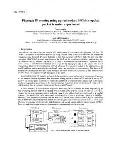
Figure 1. The mechanism for volume change in conjugated polymer. The polymer incorporates anions when it is oxidized and either expels the anion.
change upon electrochemical redox reactions which induce the insertion/removal of either dopant ions or the solvated counterions that are present in the immediate environment to maintain electronic charge balance (Fig. 1). A polypyrrole film which was synthesized electrochemically in aqueous LiTFSI solution showed 26.5% linear strain and 10.5 MPa electrochemical stress induced by electrochemical actuation [6]. As a result, when specific voltages are applied across the PPy membrane, the membrane deforms to a convex or concave form to drive the diaphragm to perform push or pull actions with a lifetime of >20,000 cycles [7]. A simple and low cost flow injection (FI) system using suggested pump was developed for detection of Fe ions (Fe2+) in aqueous solution. 1,10-Phenanthroline (C12H8N2, ortho-Phenanthroline or o-Phen) used as an oxidationreduction indicator due to characteristic color changes. The chemistry used in the present work is a simple detection of color intensity of the red complex [(C12H8N2)3Fe]2+ at 524 nm [8]. In this paper, we will describe an all-polymer pump that can be fully integrated into a microfluidic system. It is relatively low power (can be operated using a 1.5 V battery), and delivers low rates in the range 18-52 μL/min at a maximum back pressure of 11 mBar, it can be used as generic sensing platform for chemical/biological analysis and field deployments.
This work was funded by Science Foundation Ireland (Grant no. SFI 03/IN.3/1361), the Biotex Project (FP6-2004-1ST-NMP-2), Australian Research Council Linkage Grant and Korean Research Foundation (KRF2005-214-D00236).
1-4244-2581-5/08/$20.00 ©2008 IEEE
1155
IEEE SENSORS 2008 Conference
for 4 hours. After cooling the moulded parts were taken out of the mould. Fabricated check valves are shown in Fig. 3(b). The side arms stretching out from the valve body are for fixing onto the check valve holder. A 150μm thick PDMS membrane diaphragm was fabricated by casting into a glass container with a controlled amount of PDMS mixture. The membrane was then cut into the desired sizes for use in the pump assembly. Fig. 4(a) shows the photograph of the fabricated micropump which had final dimensions of 5.6mm x 16mm x 26mm. Teflon tubing (OD=1.6mm, ID=0.8mm) was fixed at the inlet and outlet. B. Preparation of Polypyrrole actuator membrane The PPy actuator was fabricated electrochemically as described previously using a porous polyvinylidene fluoride membrane (PVDF, 0.45μm pore size, 110μm thick, Millipore) as the base layer. The PVDF membrane was first sputter-coated with platinum to form a Pt layer of about 100Å thick on both sides. Polymerization of pyrrole was done using a propylene carbonate (PC, Aldrich) solution containing 0.06M pyrrole monomer (Merck) and 0.05M lithium bis(trifluoromethanesulfonyl)imide (LiTFSI, Aldrich). Approximately 0.5% (w/w) water was also added to this solution to aid deposition. The temperature was controlled at -20℃ and the polymer deposition was achieved using a constant current density of 0.3 mA/cm2 for a period of 5 hours. Prior to use, the actuator was cut to the desired size (10mm x 10mm) and stored in propylene carbonateLiTFSI solution.
Figure 2. Structure of developed microfluidic pump using PPy actuator.
(a)
(b)
Figure 3. (a) Fabricated PMMA mould for check valve using micro milling machine. (b) Casted PDMS check valve from PMMA mould.
II.
EXPERIMENTAL
A.
Design and fabrication of microfluidic pump Fig. 2 shows the structure of the developed pump. The micropump consists of two functional PMMA layers; a bottom layer incorporating two push-button type PDMS check-valves and fluidic channels, and a top layer holding a PPy membrane and PDMS diaphragm used for actuation. The pump body was fabricated using a computer aided micro milling machine. These PMMA parts were micro milled using computer aided micro milling directly operated from a CAD file. In the upper layer a pump chamber (12mm x 12mm x 1mm) with 2 cavity holes (5mm diameter, 2.8mm depth) for check valves were fabricated. A pressure sensitive adhesive (PSA) tape was used to bond together the top and bottom layers to form the pump structure.
C. Mixing chip and optical sensing module Fig. 4(b) shows a photograph of the microfluidic optical detector module that contained an microfluidic mixing chip with optical cuvette (500µm diameter, 4.5mm length), LED and photo diode. This generic microfluidic mixing chip has 2 inlets and 1 outlet. Overall length of mixing channel is 60mm with 500µm channel width. Fabricated mixing chip, LED holder and photo diode can be aligned accurately using the alignment pin. Modular design was applied so that replacement of LED and photo diode can be done easily. Fig. 5 shows the experimental setup for measuring the concentration of Fe ion using developed microfluidic pump.
Rapid prototyping was used for the fabrication of the check valves and diaphragm. First, master molds for check valve designs were produced from PMMA using CAD/CAM system (Fig. 3(a)). The check-valves and diaphragm were molded using a PDMS mixture (Sylgard 184, Dow Corning). A 10:1 mixture of solution A and B supplied was stirred thoroughly and degassed under vacuum until the mixture was completely clear and bubble free. The prepared PDMS mixture was poured onto the PMMA mold and cured at 65℃
1156
(a)
(b)
Figure 4. (a) A photograph of the fabricated microfluidic pump. (b) The optical sensing module contains microfluidic mixing chip with optical cuvette, green LED light source and photo detector.
Pumping volume (uL/stroke)
12 10 8
y = 0.938x - 0.678 R2 = 0.998
6 4 2 0 0
2
4
Figure 5. Experimental setup for measuring the concentration of Fe ion using developed microfluidic pump and optical sensing module.
10
12
14
10
12
14
(a)
D. Control circuit for system A generic microcontroller board has been developed based on the microprocessor (MSP430, Texas instruments). The board is setup with two regulated power supplies: 5V and 3.3V, 8 12-bit ADC channels, 8 I/O pins, 2 RS232 communication ports, a 2Mbit flash chip and a Real Time Clock (RTC). The background programming (employed successfully for the Phosphate System) has been used and expanded to accommodate the needs of this project [9]. The system control behaves as follows: firstly, the user specifies the period for each state change i.e., oxidation and reduction. Secondly, the program uses this defined period in conjunction with the RTC to accurately switch an external relay to toggle the potential change needed for driving the PPy actuator. Finally, the ADC channel is sampled and the current value is output over UART-RS232 to computer screen. This system setup is used a test bed for future miniaturization and has scope for a stand alone device by exploiting the onboard flash memory function. III.
6 8 Stroke time (sec)
RESULT AND DISCUSSION
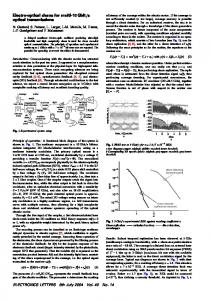
A. Performance of PPy pump To calibrate the pump performance, the inlet of the pump was connected using silicone tubing to a reservoir that contained water. The outlet was connected to a collecting container situated on a weighing balance to monitor the quantity of water pumped out into the collector. A potentiostat (1285A, Solartron) was used to drive the PPy actuator using a dc square-wave voltage of ±1.5V (vs SCE reference electrode) was used as the actuation voltage waveform. A typical pump stroke time involved switching the working electrode voltage between + 1.5V and -1.5V at 1 second intervals. The pumping volume or flow rate was determined by the weight of water delivered during the pumping experiments. Fig. 6 shows the pump performance for fluid delivery. With this pump, a maximum pumping rate of 52µL/min was achieved using an input power of 55mW with ±1.5 volt.
Pumping rate (uL/min).
60
50
40
30
20 0
2
4
6 8 Stroke time (sec)
(b) Figure 6. Measured characteristics of PPy micropump: (a) pumping volume (μL/stroke) as a function of stroke time. (b) flow rate (μL/min) as a function of stroke time. The error bars represent standard deviation from 5 repeats in both cases.
The plot of stroke time vs volume delivered by the pump presented in Fig. 6(a) showed that the amount of deformation of PPy membrane is proportional to the time at which the driving voltage is applied, and the pump flow rate can be controlled by varying the stroke time (i.e. actuation frequency), which is the switching frequency of the input electrical potentials. Fig. 6(b) shows that a limiting flow rate of 52µL/min was achieved at and above a stroke time of 6 s. Conversely, switching the PPy membrane faster than 1Hz does not produce significant enough force to deliver sample through the valves and limits the lower achievable flow rate. Linear regression from Fig. 6(a) yields a flow rate of 18µL/min for a stroke time of 1s which would be approaching the lower limit of this device. The back pressure generated by this actuator pump was determined by the height of water it could pump up a vertical tube and was found to be 11 mbar.
1157
(Ammonim ferrous sulfate hexahydrate) was diluted into several steps and passed through the microfluidic optical sensing chip using dual PPy pump. Fig. 7(b) shows that the absorbance of a solution is linear with the concentration under 0.20 mM. The lowest detectable levels of Fe2+ was 0.04 mM and working range was up to 0.20 mM. The R2 value (0.9542~0.9945) shows strong linear relationship between the concentration of Fe2+ ion and output signal from sensor.
Sensor response (AU).
4200 4000 3800 3600 y = 1916.3x + 3281.6 R2 = 0.984
3400
IV.
A self-priming micropump based on PPy actuator has been fabricated with plastic substrates without requiring expensive micro fabrication equipment or using complicated manufacturing procedures. By custom designing the check valve, actuator diaphragm and pumping chamber, combined with using in-house synthesized PPy membrane, the actuator pump is capable of self-priming, and the output flow rate control can be obtained by changing the actuation frequency. This micropump produced a maximum flow rate of 52μL/min and a nominal minimum flow rate of 18μL/min operated at ±1.5V supply. The back pressure it generates is 11mBar. This device is very low power that only consumes 55mW per stroke. A simple and low cost flow injection (FI) system with PPy micropump was developed for determination of low concentration of iron in aqueous samples.
3200 0.00
0.50 1.00 Concentration of Fe ion (mM)
1.50
(a)
Response of sensor (AU)
3900
3700
3500
y = 3339.3x + 3046.6 R2 = 0.9542
3300
y = 3808.9x + 2964 R2 = 0.9945 y = 3494.6x + 3062.2 R2 = 0.9662
3100
REFERENCES [1]
2900 0.00
0.05
0.10 0.15 0.20 Concentration of Fe ion (mM)
CONCLUSION
0.25
[2] [3]
(b) Figure 7. (a) The response of photo diode with varying concentration of Fe ion for calibration of fabricated optical detector module. (b) Measured response of optical detector module using dual Ppy pump
[4]
B. Detection of Fe ions To calibrate the optical sensing module, a stock solution prepared from 4mM iron (II) and 20 mM of 1,10phenanthrolinium chlorid monohydrat was diluted into 7 steps (0.00~1.33 mM) and passed through the microfluidic optical sensing chip and Fig. 7(a) is the concentrationresponse curve obtained. This result represents that output signal becomes saturated at 1.33 mM of Fe2+ and higher concentration than 1.33 mM shows fully saturated value. The output signal under concentration between 0~0.20 mM of Fe ions was linear (R2=0.984). The experiment was repeated three times.
[5]
[6]
[7]
[8] [9]
The intensity of red complex of 1,10-phenanthroline with Fe2+ was monitored using photo detector with dual PPy pump. A sample solution was prepared from 4 mM of iron
1158
D. J. Laser and J. G. Santiago, “A Review of micropumps,” J. Micromech Microeng, 14, pp. 35-64, 2004. P. Woias, “Micropumps-past, progress and future prospects,” Sens. Actuators B, 105, pp. 28-38, 2005. J. H. Kim, K. T. Lau, Y. Wu, G. Wallace and D. Diamond, “Performance Characteristics of a Polypyrrole Modified Polydimethylsiloxane (PDMS) Membrane based Microfluidic Pump,” Sens. Actuators A, 2008, in press. S. Ramirez-Garcia and D. Diamond, “Biomimetic, low power pumps based on soft actuators,” Sensors and Actuators A, 135, pp. 229–235, 2007. E. Smela, O. Inganäs and I. Lundstrom, “Conducting polymers as artificial muscles: challenges and possibilities,” J. Micromech. Microeng., 4, pp. 203-205, 1993. S. Hara, T. Zama, W. Takashima and K. Kaneto, “TFSI-dopped Polypyrrole actuator with 26% strain,” J. Materials Chemistry, 14, pp. 1516-1517, 2004. W. Lu, A. G. Fadeev, B. Qi, E. Smela, B. R. Mattes, J. Ding, G. M. Spinks, J. Mazurkiewicz, D. Zhou, G. G. Wallace and et al., “Use of ionic liquids for π-conjugated polymer electrochemical devices,” Science, 297, pp. 983-987, 2002. E. B. Sandell, “Colorimetric Determination of Traces of Metals,” Interscience: NY, NY, pp. 271-273, 1944. C. M. McGraw, S. Stitzel, J. Cleary, C. Slater and D. Diamond, “Autonomous microfluidic system for phosphate detection,” Talanta, 71 (1), pp. 1180–1185, 2007.