Development of Prototype Pixellated PIN CdZnTe Detectors T. Narita1 , P. Bloser1 , J. Grindlay1 , R. Sudharsanan2 , C. Reiche2 , C. Stenstrom2 1 Harvard-Smithsonian 2 Spire
Center for Astrophysics, 60 Garden St., Cambridge, MA 02138
Corporation, One Patriots Pk., Bedford, MA 01730
arXiv:astro-ph/9806179v1 12 Jun 1998
ABSTRACT We report initial results from the design and evaluation of two pixellated PIN Cadmium Zinc Telluride detectors and an ASIC-based readout system. The prototype imaging PIN detectors consist of 4 × 4 1.5 mm square indium anode contacts with 0.2 mm spacing and a solid cathode plane on 10 × 10 mm CdZnTe substrates of thickness 2 mm and 5 mm. The detector readout system, based on low noise preamplifier ASICs, allows for parallel readout of all channels upon cathode trigger. This prototype is under development for use in future astrophysical hard X-ray imagers with 10-600 keV energy response. Measurements of the detector uniformity, spatial resolution, and spectral resolution will be discussed and compared with a similar pixellated MSM detector. Finally, a prototype design for a large imaging array is outlined. Keywords: CdZnTe, PIN, MSM, pixellatedimaging detectors, hard X-ray imaging
1. INTRODUCTION Much effort has been invested in recent years into fabricating effective wide bandgap compound semiconductor detectors such as CdZnTe. These detectors have shown better energy resolution than scintillators and can be made position-sensitive by adding collecting orthogonal strips or pixels. The wide bandgap also allows these detectors to be operated at room temperature. However, the efficiency and the energy resolution of the compound semiconductor detectors are limited by the charge carrier trapping and the poor mobility-lifetime (µτ ) products for the holes. To improve these detectors, there is now increased effort into devising charge collection schemes that derive the X-ray signal primarily from electron transport.1,2 One such technique uses an array of anode collecting pixels with relatively small dimensions compared to the detector thickness. In this so-called “small-pixel regime”, the induced charge signal is mostly due to the motion of the electrons in the vicinity of a pixel, thereby reducing the dependence on the poor hole transport.1 We have shown in our previous work with pixellated metal-semiconductor-metal (MSM) CdZnTe detectors that a thick (5 mm) detector with relatively large pixels (1.5 mm square) gives good spatial and energy resolution in the 50 to 200 keV energy band.3 One of the questions we investigate here is whether detectors with large pixels on thick substrates are indeed operating in the small-pixel regime. Our work with thick CdZnTe detectors having relatively large pixels is motivated by the need for a large area hard X-ray astronomical survey telescope.4 A wide-field instrument capable of imaging with arcminute angular resolution in the 10 - 600 keV energy band is required for Gamma Ray Burst (GRB) localization and deep surveys of non-thermal astronomical systems. A large area detector is needed for imaging in the hard X-ray band since focusing optics cannot be used at energies greater than ∼ 80 keV. Instead, one must rely on modulated imaging techniques such as coded aperture imaging. Our hard X-ray telescope (EXITE) group at Harvard is working collaboratively with Spire Corporation to build and characterize pixellated CdZnTe detectors with low leakage current. We are experimenting with the addition of PIN blocking contacts on CdZnTe to reduce the bulk leakage current observed on standard MSM detectors without blocking contacts.5 PIN contacts have already been used with CdTe substrate with good success. If PIN contacts can improve the performance of CdZnTe, that may allow us to build economically large detector arrays using inexpensive lower grade CdZnTe. In this paper, we will discuss initial results from our program to develop pixellated PIN contact CdZnTe for future use in a hard X-ray imaging telescope. Further author information: (Send correspondence to T. Narita) T.N.:
[email protected] R.S.:
[email protected]
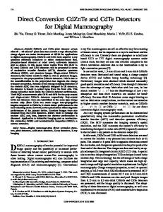
Figure 1. The 5 mm PIN CdZnTe detector. The wirebonds are connected to the anode pixels. The detector is illuminated from underneath the chip carrier (cathode side).
2. CZT P-I-N DETECTOR DEVELOPMENT 2.1. Detector and Readout Electronics Our detectors are spectroscopic grade High Pressure Bridgeman CdZnTe with 10% Zn from eV Products. The substrate sizes are 10 × 10 × 2 mm and 10 × 10 × 5 mm. 1µm layers of CdS (n-type) and ZnTe (p-type) are deposited on to the CdZnTe surface by thermal evaporation to form a diode-like blocking contact (PIN).5 A mask is used on the CdS side to form 16 1.5 × 1.5 mm square pixels with 0.2 mm gaps between pixels. A 1 mm wide guard ring is also placed around the array of pixels with a 0.2 mm gap separating the array from the guard ring. A layer of indium is finally deposited over the CdS to form the metal contact. Figure 1 shows the pixel side of the detector and the discrete components of the readout electronics. The CdZnTe detector is attached to a ceramic substrate and mounted in a chip carrier. A window in the metal chip carrier allows X-rays to impinge on the cathode surface through the ceramic substrate, which imposes a low energy cutoff at ∼ 20 keV. Wirebonds are used to connect the pixels to the pins of the chip carrier. The cathode side of the detector is connected to an eV Products 550 preamplifier and biased to a large negative voltage. The output of the preamp is shaped by a NIM module fast shaping amplifier and used as an event trigger. The anode pixels are biased to ground via 100 MΩ resistor and AC coupled to two 8 channel charge sensitive preamplifer–shaping amplifier Application Specific Integrated Circuits (VA-1 model ASIC) manufactured by Integrated Device Electronics (IDE). A shaping time of 1µs is used and the ASIC response is measured to be linear over the energy range of interest. The ASIC outputs are amplified and simultaneously held when triggered by the fast shaped cathode pulse. The 16 held signals are converted by a PC/104 single-board-computer and a daughter board ADC card, and written out via parallel port interface to a PC on an event-by-event basis. To determine the noise in the system due to the ASIC, stray capacitance, and leakage current, test pulses (∼ 1 mV) can be injected through 2 pF capacitors into the ASIC in parallel with the detector output. The gains of the post-ASIC amplifiers are not identical, but we have calibrated each channel using known X-ray lines.
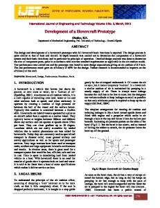
2.2. Leakage Current Since the bulk leakage current contributes to the signal noise and limits the operating detector bias, we compared the leakage currents between PIN and MSM detectors. We used a Keithley 237 high voltage source to bias each pixel of the PIN detector in 50 volt steps from +500 to -500 volts. The leakage current measurements were taken in the dark and at room temperature. The typical leakage current across the 2 mm thick CdZnTe was 10 nA at -500 volts and the current across the 5 mm thick detector was 5 nA at -500 volts. The leakage current from a similarly pixellated 10 × 10 × 5 mm MSM detector3 at equal bias was 15 nA (Fig. 2). The PIN detector clearly exhibits the standard diode current-voltage relation, confirming the effectiveness of blocking contacts on reducing the bulk
2.0•10-8
2.0•10-8
1.0•10-8 Leakage Current (Amps)
Leakage Current (Amps)
3.0•10-8
1.0•10-8
0
-1.0•10-8
0
-1.0•10-8
-2.0•10-8 -400
-200
0 Bias Voltage (Volts)
200
400
-400
-200
0 Bias Voltage (Volts)
200
400
Figure 2. Comparison of the leakage current between PIN and MSM detectors (each 5 mm thick). At -500 volts bias, the PIN detector shows 5 nA of leakage current while the MSM detector shows 15 nA. leakage current. The bulk resistivity of the PIN detector is estimated to be 2 × 10¹¹ ohms-cm, while the MSM detector without the blocking contact has a resistivity of only 6.7 × 10¹⁰ ohms-cm. Additional experiments with various surface passivations are planned to further reduce the leakage current to few nanoamps at comparable bias voltage. The surface leakage current contribution was also measured by placing a small difference in potential between an edge pixel and the normally grounded guard ring (separated from the pixel by the 0.2 mm gap). The typical surface current was 0.8 nA at 5 volts for the PIN detector and 1 nA at 1 volt for the MSM detector. Thus the surface leakage current in the PIN detector is significantly reduced, which has important advantages for guard ring designs, as discussed below (Sec. 2.6). The charge transport property of a semiconductor is one of the important parameters in determining the detector performance. Large values for the charge carrier mobility (µ) and the mean drift time (τ ) are sought for good charge collection. We measured the electron µτ product for the PIN detectors and the MSM detector by irradiating the cathode contact with a 241 Am source (60 keV) and recording the peak pulse height amplitude value for pulses shaped with 1µs time constants at various bias voltage values. By fitting the result with the Hecht relation,6 we find that typical µτ for the MSM detector is 2.8 × 10⁻³ cm2 V −1 , whereas the PIN detector µτ are 5.1 × 10⁻³ cm2 V −1 and 2.0 × 10⁻³ cm2 V −1 for the 2 mm and the 5 mm respectively.
2.3. Energy Resolution A primary concern when using a CdZnTe substrate is the uniformity of the energy resolution across the detector. Small structural defects in CdZnTe can trap charge carriers and thereby degrade the local energy resolution. We uniformly illuminated both the 2 mm and the 5 mm detectors with 241 Am and 57 Co at -500 volt bias to determine the energy resolution of all the pixels, and also measure any depth-dependent effects. The energy resolution is defined as the ratio of the FWHM width of the Gaussian photopeak to the peak energy. Test pulses were simultaneously injected to measure the electronic noise contribution to the photopeak. The typical energy resolution at 60 keV was ∼ 7 − 10% for the 2 mm detector and ∼ 9 − 11% for the 5 mm detector. As seen from the pulser, most of the spread in the resolution is due to electronic noise. The primary noise contribution is the stray capacitance from the discrete components on our detector interface card, as also measured from the MSM detector.3 By subtracting the test pulser width in quadrature from the photopeak width, we estimate the intrinsic detector resolution at 60 keV to be ∼ 3.2 − 4.8% for the 2 mm detector and ∼ 4.5 − 6.5% for the 5 mm detector. At 122 keV, we estimate the intrinsic detector resolution, following the same process of test pulser subtraction, to be ∼ 2.5 − 4.0% for the 2 mm detector and ∼ 4.0 − 5.2% for the 5 mm detector. Figure 3 shows the typical spectrum obtained from one pixel for both the 241 Am and 57 Co sources. At the same -500 volt detector bias, the MSM detector gave comparable energy resolution of ∼ 3.8 − 5.5% at 60 keV. The detector energy resolution is found to be fairly uniform for either of the detectors at two energies. No significant depth-dependent variation in the energy resolution was observed. Although the escape peaks at ∼ 30
Figure 3. Typical spectra from the 5 mm PIN detector biased at -500 volts. 241 Am (60 keV) and 57 Co (122 and 136 keV) spectra are shown in the left and right spectra, respectively, together with their pulser peaks (rightmost peak in each spectrum) for comparison. keV are visible, the lower energy Am and Np lines below ∼ 20 keV could not be measured due to absorption by the ceramic substrate. The 5 mm PIN detector’s energy resolution was the worst of the three detectors we tested, but this could be attributed to the poorer quality of the CdZnTe used, as seen by the smaller electron µτ (Sec. 2.2). At higher bias (-700 volts), the 60 keV energy resolution of the 5 mm PIN detector improved to ∼ 3.5 − 5.0%, or comparable to the 5 mm MSM detector at -500 volt bias. The improvement in the energy resolution of the PIN detector at larger bias may imply that the detector is not fully depleted at 500 volts.
2.4. Photopeak Efficiency The primary benefit from operating a pixellated detector in the small-pixel regime is the improved photopeak efficiency. We used 241 Am and 57 Co beams, collimated to ∼ 0.8 mm diameter, centered on the pixels of the 2 mm and the 5 mm PIN detectors, biased to -500 volts, to compare the amount of low energy tailing in the photopeaks. By using a collimated X-ray beam, any contribution to the photopeak tail due to incomplete charge collection from X-ray interactions in the interpixel region can be neglected. Each spectrum is fit using a χ2 minimizing Gaussian and an exponential tail. We define the photopeak efficiency as the ratio of the counts in the Gaussian photopeak to the total counts in the Gaussian plus the exponential tail. Figure 4 shows the spectra for the two detectors at two X-ray energies and their respective fits. The 241 Am photopeak efficiencies are 79.0 ± 2.8% and 88.9 ± 4.2% (1σ) for the 2 mm and the 5 mm detectors, while the respective 57 Co photopeak efficiencies are 42.5 ± 0.9% and 77.5 ± 2.5%. The difference in the photopeak efficiencies between the 2 mm and 5 mm detectors illuminated with 241 Am is small. This is expected since the average depth of interaction by a 60 keV photon in CdZnTe is ∼ 0.1 mm. At this small penetration depth, the small pixel advantage of single-charge collection is minimal. At 120 keV, the X-rays penetrate farther (∼ 1 mm) into the CdZnTe. The distribution of interactions occurring deeper in the weighting potential, and some contribution from electron trapping, will likely produce a larger photopeak tail compared to the 241 Am X-rays. It is clear however, when comparing the 57 Co spectrum on the 2 mm detector to the 5 mm detector, that our 5 mm detector is indeed operating in the small-pixel regime and maintaining a reasonable photopeak efficiency.
2.5. Position Resolution The imaging quality of a pixellated detector is limited by charge spreading due to ionizing photoelectron, Compton scattering of the primary photon, and diffusion of electron-hole clouds under bias potential between the collecting electrodes. We used collimated and full-flood beams to measure the point-spread-function (PSF) of our relatively large pixel detector and to determine the best method of recovering our signal. First, we investigated the amount of cross talk between pixels without any contamination from photon interaction in the interpixel region. Two spectra were recorded with 241 Am and 57 Co beams, collimated to ∼ 0.8 mm diameter, centered on one pixel of the 5 mm PIN detector. In the 241 Am spectra, there was no evidence of cross talk between
300 250
A
300
Counts
Counts
400
200 100
150 100 50
350 400 450 500 550 Channel
350
800
C Counts
Counts
800
B
200
600 400
400 450 500 Channel
550
D
600 400 200
200 600
800 1000 Channel
1200
500 600 700 800 900 1000 Channel
Figure 4. Photopeak efficiency fits for the 2 mm and the 5 mm detectors at two collimated beam energies. A, 241 Am on 2 mm CdZnTe. B, 241 Am on 5 mm CdZnTe. C, 57 Co on 2 mm CdZnTe. D, 57 Co on 5 mm CdZnTe. The best-fit Gaussian (photopeak) and exponential tail components are shown as dashed curves which sum to the solid curve. the center irradiated pixel and any of its nearest neighbors. But when we used a 57 Co beam, we found a small broadened photopeak at ∼ 100 keV energy in each of the four nearest neighbor pixels at ∼ 0.9% of the count rate of a center pixel (Fig. 5). The far neighbor pixels (2 pixels from center pixel) showed only the normal background and there was no sign of a photopeak. Figure 8 shows the total number of counts in the center pixel compared to the neighbors for a collimated beam. We believe the photopeak cross talk is due to Compton scattered 122 keV and 136 keV photons. The Compton scattering cross section at this energy range is about one order of magnitude less than the photoelectric absorption cross section. The range of scattering angle for a photon, which originally penetrates the CdZnTe at normal incidence angle at the edge of the collimated beam and then scatters into the next pixel, is ∼ 30 − 100 degrees. This would correspond to an observed near neighbor photopeak in the energy range of ∼ 115−90 keV. Although these interactions are unrecoverable, it appears they will have a minimal effect on our PSF. Next, we measured the amount of cross talk due to charge sharing between pixels from photon interaction in the interpixel region. We recorded simultaneous 16 channel spectra with full-flood beam of 241 Am on the 5 mm detector. From the spectra, we extracted only those events which had their highest pulse height on a given center pixel. An “extracted” spectrum should show the distribution of events where the majority of the energy was deposited in this center pixel and remaining charge, if any, spread among the neighbors. The resulting 241 Am spectra (Fig. 6) show each of the near neighbors with a residual low energy tail and the center pixel missing its portion of the low energy tail. The missing low energy counts are presumably the amount of charge normally shared from the neighbor pixels. The sum of the counts found in the near neighbor spectra is ∼ 20% of the counts in the center pixel photopeak. The far neighbor pixels did not show any of sign of the residual tail. The extracted full-flood 57 Co spectra (Fig. 7) show that ∼ 36% of the counts in the 122 keV photopeak is spread among the near neighbors as low energy residuals. Our simple interpretation is that we are observing charge cloud sharing between pixels. The effective pixel area
Figure 5. Collimated 57 Co spectrum and its nearest neighbors. Compton scattered photons from the 122 keV and 136 keV photons produce small photopeaks in the neighboring pixels. There was some variation in the gains between channels. extends into the interpixel region where it can collect some fraction of the charge cloud generated by an incident photon. These low energy tails do not appear in the collimated image (Fig. 5) since the collimated beam would not have produced charge clouds near the pixel edge where it can be shared between pixels. If the size of a charge cloud from a 60 keV photon is on the order of our interpixel spacing (0.2 mm), we estimate that ∼ 25% of the events occuring in a pixel will have a fraction of its energy deposited in one of its near neighbor pixels. The lack of counts in the far neighbor pixels indicate that our PSF is fairly tight (Fig. 8). Thus any post-detection processing, such as summing signals of adjacent pixels to recover the total deposited energy, can be done on our detector with at most nine pixels.
2.6. Effect of Guard Ring Bias Another method of increasing photopeak efficiency is placing a non-ground bias potential on the guard ring around the pixels. The additional potential sets up an electric field to deflect the electrons toward the pixels, increasing their collection efficiencies. This method has proved effective for single element detectors7 and has been investigated for strip detectors.8 To see whether a similar effect could be seen on a pixellated detector, we full-flood illuminated the 5 mm PIN detector with 241 Am source and changed the guard ring potential from ground to -25 volts with the detector cathode biased at -500 volts. The guard ring surrounds the full 4 × 4 array and hence it is only adjacent to the 12 pixels around the edge. The resulting spectra were analyzed for any change in efficiency or energy resolution, especially for the edge pixels next to the guard ring. We found that the photopeak efficiencies of the inner four pixels, which are surrounded by other pixels, averaged −0.3 ± 0.5% change. There were no changes in their energy resolutions. The edge pixels, which are bound on one side by the guard ring, averaged 2.5 ± 0.5% improvement. The four corner pixels, surrounded on two sides by the guard ring, had their photopeak efficiencies improved on average by 5.5 ± 1.7%. The complete detector response is shown in Figure 9. The general improvement in the photopeak efficiencies, especially for the outer pixels, seem to indicate that
Figure 6. The “extracted” (see text) spectrum from a full-flood 241 Am showing the effect of charge sharing between neighboring pixels. The low energy peak in channel ∼ 300 is the escape peak (∼ 30 keV). Notice the lack of low energy tail below 25 keV in the center pixel compared to the unextracted spectrum in Figure 3. additional guard ring bias could be effective for pixellated detectors. We did not use a bias greater than 25 volts because two of the pixels (including one corner) exhibited partial breakdowns across the narrow gap (0.2 mm) between the pixel and the guard ring. We are currently investigating the cause of this effect. As noted in Section 2.2, the leakage current between a pixel and a guard ring is larger for the MSM detector than for the PIN detector. Therefore, we believe the use of PIN blocking contacts will enhance the efficiency of a pixellated detector with a biased guard ring. For our current pixel mask geometry, the guard ring is adjacent to at most two sides of the the outer pixels. Such a design may be improved by placing a guard ring around each pixel. We are currently testing a device which incorporates this new design and will allow larger bias potentials for the guard ring.
3. CONCLUSIONS The results presented in this paper show the potential for using PIN contacts on CdZnTe for use in imaging hard X-ray detector. The use of blocking contacts show the anticipated improvement in the detector leakage current compared to the standard MSM detector. With the addition of blocking contacts, it may be possible to economically construct a large array detector using lower resistivity CdZnTe. The two PIN detectors we tested gave similar energy resolutions, and the pixel to pixel responses were uniform across the detectors. We did show however, that the 2 mm and 5 mm thick detectors with same pixel size gave very different photopeak efficiencies. We attribute this to the effectiveness of the small-pixel effect even for relatively large (1.5 mm) pixels. When determining the spatial resolution of our detector, we found that the amount of charge spreading across pixels was relatively small. We will need to consider at most the nearest neighbor pixels for any post-detection centroiding. Finally, we found that biasing the guard ring with a small steering potential is effective for pixellated detectors. Our goal is to eventually build a 1 m2 pixellated detector array for a hard X-ray imaging telescope. We plan to construct this detector using an array of interchangeable modular basic detector elements (BDE), which consists of
Figure 7. The “extracted” (see text) spectrum for a full-flood 57 Co. The small Compton scattered photopeaks seen in the collimated spectrum (Fig. 5) do not appear in this extracted spectrum. Instead, we are seeing the spread of the photoelectron generated charge cloud.
Figure 8. The image of a collimated 57 Co beam (left) and the extracted image from one pixel under full-flood illumination (right). In the collimated image, there is very little cross-talk between pixels. The extracted image shows the residual charge sharing among neighbor pixels and the resulting PSF.
Figure 9. Individual pixel improvements in photopeak efficiency when the outer guard ring is biased with a steering potential. The uncertainty in the photopeak fit is ±0.5% (1σ). One of the foreground edge pixel (6) was not functioning. 2 × 2 array of 1 cm2 CdZnTe.4 Each BDE will be designed to operate with a single 64 channel self-triggering ASIC and it will be made compact to allow for seamless tiling. We are presently testing a prototype BDE which consists of two side by side 1 cm2 CdZnTe detectors epoxy bonded onto a ceramic substrate (flip-chipped), and read out by a single 32 channel self-triggering ASIC (VA/TA from IDE). Along with the lab assessment of the detector, we also plan to study the CdZnTe background in the near-space environement when we integrate the prototype BDE with the next EXITE2 balloon flight, scheduled for Spring 1999.
ACKNOWLEDGMENTS We thank Einar Nyg˚ ard of Integrated Device Electronics for advice and assistance with the ASIC. This work was supported in part by NASA grant NAG5-5103.
REFERENCES 1. H. Barrett and J. Eskin, “Charge transport in arrays of semiconductor gamma-ray detectors,” Phys. Rev. Lett. 75, pp. 156–159, 1995. 2. P. Luke, “Unipolar charge sensing with coplanar electrodes - application to semiconductor detectors,” IEEE Trans. Nucl. Sci. 75, p. 207, 1995. 3. P. Bloser, T. Narita, J. Grindlay, and K. Shah, “Prototype imaging cdznte array detector,” in Semiconductors for Room-Temperature Radiation Detector Applications II, R. James, T. Schlesinger, P. Siffert, M. Cuzin, M. Squillante, and W. Dusi, eds., Proc. MRS 487, 1998. 4. J. Grindlay, “Balloon-borne hard x-ray imaging and future surveys,” Adv. Space Res. 21, pp. 999–1008, 1998. 5. R. Sudharsanan, G. Vakerlis, and N. Karam, “Fabrication and characterization of cdznte radiation detectors with a new pin design,” J. Elect. Mat. 26, pp. 745–749, 1997.
6. K. Hecht, “Zum mechanismus des lichtelektrischen primarstromes in isolierenden kristallen,” Zeits. Phys 77, pp. 235–243, 1932. 7. J. Butler, “Novel electrode design for single-carrier charge collection in semiconductor nuclear radiation detectors,” Nucl. Instr. Meth. A 396, pp. 427–430, 1997. 8. K. Slavis, W. Binns, P. Dowkontt, J. Epstein, P. Hink, J. Matteson, F. Duttweiler, G. Huszar, P. Leblanc, M. Pelling, R. Skelton, and E. Stephan, “High altitude balloon flight of czt detectors for high energy x-ray astronomy,” BAPS 43, p. 1087, 1998.