Original scientific paper
http://doi.org/10.24867/JGED-2016-1-019
Development of tactile floor plan for the blind and the visually impaired by 3D printing technique Abstract The aim of the research was to produce tactile floor plans for blind and visually impaired people for the use in the museum. For the production of tactile floor plans 3D printing technique was selected among three different techniques. 3D prints were made of white and colored ABS polymer materials. Development of different elements of tactile floor plans, as well as the problems and the solutions during 3D printing, are described in the paper.
Raša Urbas, Matej Pivar, Urška Stankovič Elesini
Key words tactile floor plan, blind and visually impaired, 3D printing, maps, floor plan, tactile museum
Corresponding author: Raša Urbas e-mail:
[email protected]
University of Ljubljana, Faculty of Natural Sciences and Engineering, Snežniška 5, 1000 Ljubljana, Slovenia
First recieved: 22.04.2016. Accepted: 20.05.2016.
Introduction 3D printing is a process of creation three-dimensional solid objects from adequately prepared files, in which design is diagonally shaped. For this printing technique a term “Rapid Prototyping” is often used, thus it designates technologies, which deposit materials for 3D model construction in several layers. Different shapes and forms of objects are created with additive process in which sequential layers of diverse material are added one on the top of another. The process starts with the production of virtual object in a 3D modelling software or by using 3D scanner, which creates an object copy (3DPrinting.com, 2015; Muck & Križanovskij, 2015; Thomas & Claypole, 2016; ). 3D printers use different technologies, which significantly differ in the method of applying layers one on another. American Society for Testing and Materials (ASTM) has defined seven different technologies of additive procedures, which enable creation of 3D objects: 1. Vat photopolymerization; 3D printer uses photopolymer resin, which polymerizes under UV light. The most common type of this technology is stereolithography.
2. Material jetting; the material is applied in small droplets from a small nozzle, layer by layer. Created 3D object is hardened (polymerized) by UV light. 3. Binder jetting; basic powder material and liquid binder are used in this technology. The powder material is spread in uniform layer, while the binder is added on the top through the nozzle following with another layer of powder, layer of binder etc. repeating until 3D object is formed. 4. Material extrusion; the most commonly used process, which presents targeted loading – Fused deposition modeling, where 3D objects are formed by depositing heated material layer by layer (material is heated inside the nozzle). Material hardens almost immediately after leaving the nozzle. 5. Powder bed fusion; most often includes so-called Selective laser sintering, where a laser is used as a power source for binding i.e. sintering powdered materials of plastic, metal, ceramics and glass, into 3D form. 6. Sheet lamination; this technology can be divided into two processes –Ultrasonic Additive Manufacturing (UAM) and Laminated Object Manufacturing (LOM). UAM mainly uses sheet laminators for the production of metal multilayer
Journal of Graphic Engineering and Design, Volume 7 (1), 2016.
19
sheet constructions, which are welded together ultrasonically by using outer force with additional Computer Numerical Control (CNC) for shaping the final object, while LOM uses similar technology, but with paper or polymers, linked together with different adhesives. Later technique uses crosshatch for easier removal of excessive material after object construction. 7. Direct energy deposition; the technology is most often used in high-tech metal industry. Metal material, provided in powder form or wire, is deposited from the nozzle onto the surface of the object. On its way, the material is melted using laser, electron beam or plasma arc, and layer by layer constructed into an object (3DPrinting.com, 2015; Thomas & Claypole, 2016). 3D technology is suitable for printing different 3D objects, but it can also be successfully used for printing communicational tools for blind and visually impaired e.g. Braille, 3D maps, etc. Until recently, Braille was mainly printed with embossing, less often by screen printing and other printing techniques. Nowadays, 3D printing is becoming more and more popular, not only for printing Braille but also for printing tactile objects, maps, floor plans etc. (Jaquiss, 2011; Butler Millsaps, 2014). However, it is important to emphasize that the costs of manufacturing 3D tactile elements are still relatively high compared to the conventional printing procedures, due to which this new technology hasn’t fully asserted in the area of printing for the blind and the visually impaired. Production of tactile floor plans require a lot of ingenuity. They are usually made of different materials like wood, metal, plastics etc., by different techniques, which are expensive and time consuming and have different advantages as well as disadvantages. Tactile floor plans, for example, can be made by the use of the microencapsulated paper, but their mechanical resistance and durability are very poor, therefore their exploitation time of use is limited. Thus, the aim of our research was to produce a)
adequate tactile recognizable and above all resistant and durable tactile floor plans by using 3D printing. Tactile floor plans made in our research, were developed for the Technical Museum of Slovenia, Museum of Post and Telecommunication (Polhov Gradec, Slovenia). Our first idea was to print tactile floor plans with screen printing technique, where we wanted to use special 3D expandable printing inks, however the idea was abandoned due to the questionable durability of prints. In view of the above, we were trying to find a suitable technique, which would enable production/ printing of tactile floor plans with sufficient durability, precision and adequate height. Therefore, 3D printing was selected, because we’ve assumed that with this technique proper results could be achieved.
Materials and methods Materials In our research three differently colored ABS polymer material has been used for printing tactile floor plans – white, red and blue (3D Systems, USA), which properties are presented in Table 1. Table 1 Properties of 3D printing polymer material Property Composition Filament thickness [mm] Color [-] Softening temperature [°C] Degradation temperature [°C] Density [g/cm3]
Value acrylonitrile butadiene styrene (ABS) 1.75 white, blue, red 105 > 300 1.05
b)
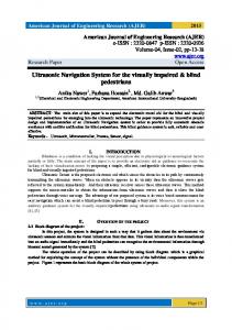
»»Figure 1: 3D printer CubePro Duo (a) and presentation of printing by extruding the polymer from a nozzle (b)
20
Table 2 Printing conditions on 3D printer Cube Pro Duo Property
Value
Nozzle temperature [°C]
260
Chamber temperature, providing constant printing conditions [°C]
60
Nozzle diameter [mm]
0.4
Filament diameter [mm]
1.75 - - - -
Model preparation:
Printing procedure In the research 3D printer CubePro Duo (3D systems, USA) was used for printing tactile floor plans (Figure 1a). It enables the use of different polymer materials such as acrylonitrile butadiene styrene (ABS), polylactide (PLA), nylon and water-soluble thermoplastic supporting material (ABS). CubePro Duo printer prints objects by the extrusion of material from the cartridge through the printing nozzle. Material is extruded through the printing head in a thin filament, 0.4 mm in diameter. Movement of the printing head is coordinated by the printing plate, which gradually lowers its position after each printed layer. New layer is printed onto previous, therefore an object is printed from the bottom up (Figure 1b) (3D Graphic software, 2012; 3D Systems, 2015).
resolution 200 μm (5 printed/built layers in 1 mm2) filler type: »strong« (50% fill) filler shape: diamante without support materials
Graphic layouts for tactile floor plans were designed in Blender (Blender Institute, Netherlands), an open source software. Printing conditions are presented in Table 2.
Methods Samples of printed tactile floor plans were analyzed by scanning electron microscope (SEM, JSM 6060 LV, Jeol) and digital microscope Dino-Lite Pro AM-413T (AnMo Electronics Corp., USA).
Results and discussion
Printer enables two-color printing. When printing monochrome objects, maximal dimensions of 24.29 cm × 23 cm × 27.04 cm be printed, while when printing in two-color those dimensions are reduced. Individually printed layers can be produced in three variables: 70, 200 or 300 μm.
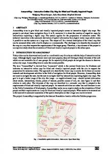
Production of tactile floor plans started with the minimization of information to basic e.g. most important. With the help of floor plan blueprints of museums first and second floor, first suggestions of graphic layouts were designed in Blender (Figure 2). On designed graphic layouts of tactile floor plans walls, staircase, doors and a point, which indicates the location of the visitor, were marked. In accordance with this, the
a)
b)
»»Figure 2: First designed suggestions of tactile floor plan of (a) the first and (b) the second floor in the museum
Journal of Graphic Engineering and Design, Volume 7 (1), 2016.
21
a)
b)
c)
»»Figure 3: Faze development of initially designed (a), an intermediate stage (b) and final design of tactile staircase element (c) legend with elements marking museum’s path direction, staircase, thresholds and point of visitor’s location, was added. Initial graphic layouts of tactile floor plans were designed according to different types of tactile maps found in the literature (Rener, 1992; Schuffelen, 2002; Kaneko & Oouchi, 2010; Braille Authority of North America (BANA) & Canadian Braille Authority (CBA), 2011; 3ders.org, 2014; Butler Millsaps, 2015). Initial graphic layouts of tactile floor plans were later slightly modified as follows: • initially designed tactile staircase (Figure 3a)
was through an intermediate stage (Figure 3b) redesigned into a tactile element, consisted of six parallel thicker lines (Figure 3c); • we intended to print the names of all exhibition rooms in Braille and Latin alphabet, so that the tactile floor plans would be usable/ suitable also for normally sighted people; • the path, from the staircase to the first exhibition room, was marked with small isosceles triangles; • the same, but smaller isosceles triangles were used for marking the space between the doors, where hazardous, raised thresholds, visible to normally sighted, are located (Figure 3c). On the basis of the first graphic layout designs, the following preliminary prints with 3D printer were printed: a) prints of Braille; b) prints of Braille and Latin and c) prints of walls, defining the exhibition area. a)
b)
Ad a.) Printing Braille on the 3D printer didn’t cause any major problems. Several printing attempts were performed mainly because we wanted to print Braille dot with parameters, which would meet the standards of the height (0.5 mm) and the diameter of Braille dot (1.5 mm), as well as the distance between the center of two Braille dots (2.5 mm) (Deutsches Institut für Normung e. V., 2007; Österreichisches Normungsinstitut, 2008; Fajdetić, 2012; International Standardization Organization, 2013). The appearance and the cross section of preliminary printed dots are shown in Figure 4. The Braille dots were composed of four layers, had adequate height (0.6 mm) and diameter (1.6 mm – 1.8 mm) (Figure 4c), however they had very sharp and disturbing edges (Figure 4a). Dots were thus appropriately treated (polished), thus the edges became smoother and more pleasant to touch (Figure 4b). Ad b.) The initial idea was to print tactile floor plans, which would be suitable for blind and visually impaired, as well as for normally sighted, but during printing we came across some serious problems. 3D printing technique is still in its developing phase and therefore, despite its great advantages, it also has some limitations. Our goal was to print Latin letters in red on the white base of tactile floor plans, so the letters would be clearly visible for visually impaired and normally sighted. But as the 3D technology uses the method of rending, printing (e.g. layering) red Latin letters would consequently cause them to stand out from the liner (base). Such prints wouldn’t be appropriate for blind and visually impaired, since the letters would actually be an additional disc)
»»Figure 4: Untreated Braille dot produced by 3D printer (a), treated Braille dot (b) and its cross-section (c) (SEM; 22× and 20× magnification)
22
turbing factor in the tactile perception. To avoid this unwanted effect, we have tried to “engrave” the red Latin letters into the white base, so they would be in the same level as the liner. The attempt failed. Namely, to achieve the desired result, it was necessary to redesign the graphic layout of the 3D model in Blender. For this operation the transformation tool Boolean Modifier was selected. Tool creates a single compound object out of two mash objects, using its own algorithm of disjunction (intersection), by which empty spaces, in the shape of individual letters, were formed (Figure 5a above). Unfortunately, newly designed 3D mash model of text (e.g. letters) became extremely complex (Figure 5a below). The excessive amount of information caused inadequate performance of the print nozzle, resulting in emerging errors in the shape of unevenly deformed surfaces of prints (Figure 5b). This problem could be eliminated by repairing the entire 3D mash (every surface, every edge and every vertex) separately, adjusting each element (letter) to the print nozzle, which proved to be too complicated. In addition, another problem occurred, arising from the identical size of individual elements (e.g. letters) taken from the liner and ones in the liner. Because of the identical size the same position (wall) was printed twice – once printing the red letters and once printing the white liner. Moreover, the extrusion line slightly expanded and became more warp. Altogether caused unevenness and irregularities of printed surface (Figure 5b). Hence, in modeling of each element (e.g. letter) an addition of expanding factor needed to be considered (in our case 0.4 mm). This modification of the 3D mash revealed to be time consuming, due to the fact that the elements (e.g. letters) could not be symmetrically
increased or decreased. Similar occurred with printing numbers, therefore hereafter we have focused only on Braille, which was printed without any major problems.
a)
b)
Ad c.) Printing of walls, which define the individual exhibition area in the museum, and the Braille dots caused no problems. It was established after printing, that the wall height was a bit too high (4 mm). Therefore, in the next printing attempt the wall height was reduced to 2 mm, which was still sufficient for tactile recognition. On the bases of the preliminary printing attempts and the first printed graphic layouts of 3D floor plans we’ve decided: • to include the names of exhibition area only
in Braille and to exclude ones in Latin; • that the tactile staircase element is adequate,
but it extends too far into the hall area (Figure 2b), so we decided to reduce the number of tactile staircase element lines from six to four; • that by reducing the tactile staircase element length more space was created on the floor plan, so it was possible to circularly allocate arrow shaped isosceles triangles, indicating museums path from the staircase to the exhibition area (Figure 6); • to add the legend of individual elements representing: staircase (three thicker parallel lines), museums path and raised door thresholds between separate museum exhibition areas (isosceles triangle), and the dot (small round circle) denoting the visitor’s location inside the museum.
»»Figure 5: Complex mesh of the 3D model of text and (a) unsuccessful attempt of simultaneous 3D printing of Braille and Latin letters (b)
Journal of Graphic Engineering and Design, Volume 7 (1), 2016.
23
Based on the findings, we have designed new graphic layout of tactile floor plans in Blender (Figure 6).
Listed irregularities were corrected and redrawn in Blender, where a new graphic layout was designed. This new tactile floor plan was firstly printed on the microencapsulated paper and tested among children at the Institute for blind and visually impaired youth (Ljubljana, Slovenia). With the help of practice tests we have established that: • arrow shaped isosceles triangles, which were
»»Figure 6: Redesigned 3D floor plan In accordance with designed graphic layouts we’ve tried to produce a tactile floor plan in red and white combination. On the 3D printer simultaneously white liner, including Braille dots, and red elements were printed. Two printing heads have been used for printing white and red ABS polymer. When the printer achieved the height, on which red elements started to print, firstly two red layers were alternately printed, then two white layers, again two red and so on, until the adequate height of 3D design was achieved. Due to the size of the tactile floor plan and the dimension limitations of the 3D printer, designed tactile floor plan was divided into two parts, which were printed separately and then later joined on the basis of Plexiglas. Prototype of described tactile floor plan is presented on Figure 7.
»»Figure 7: Prototype of tactile floor plan Prototype of tactile floor plan was successfully produced, but it still had some irregularities:
marking the museums path from the staircase to the first exhibition area, were completely unusable (Figure 8a), namely blind children were too engaged defining where isosceles triangles were pointing, instead of using them as a direction markers. Therefore it was decided to change isosceles triangle shaped arrows into equilateral triangles (e.g. empty arrow heads), as shown on Figure 8b. • the Braille cell (e.g. letter) was too large, and the children had difficulties reading the content; it was decided that the Braille cell needed to be slightly reduced, in particular the distance between individual letters. Later, it was established that the error occurred during the conversion of text from the Latin alphabet into the Braille typeface, which was performed in Word (Microsoft). Namely, this software conversion doesn’t fully consider the definitions of Braille standard, therefore individual Braille cells were too remote from each other; • because of the larger Braille cell, the names of exhibition areas were considerably clustered between the walls of the tactile floor plan, with the first and last letters almost touching the walls. Due to mentioned, children were almost unable to detect the beginning and the ending of the exhibition area name; • the walls of exhibition areas, other tactile elements and Braille were adequate in height, and as such distinguishable from the liner. Based on the findings once again we designed new, revised graphic layout of 3D floor plan (Figure 8), printed them with microencapsulated paper and again verified with blind and visually impaired children. Research has shown that:
• orientation of the exhibition area was
inappropriate according to the position of the tactile floor plan; • four lines, presenting staircase, were still reaching too far into the hall area; • there was a wall missing in designed graphic layout; • graphic layout of some doors was not correct according to the actual positioning inside exhibition area, etc.
24
• regardless to the differently designed shape of
arrows designating the museum’s path, they continued to dismay the children. Therefore, it was decided that the museum’s path will not be designated and only arrows, marking thresholds between the doors, were left; • the children were able to more easily read the narrowed and slightly reduced Braille;
a)
b)
»»Figure 8: Comparison of two newly designed tactile floor plans with differently shaped arrows designating the museum’s path (a and b) • the children liked Braille printed with 3D
printer, which was, due to the sharp edges, appropriately treated (polished); • the children (and their teachers) were impressed by the idea that the walls on 3D floor plans were slightly higher than other elements. Responses of the children led us very close to the final design of tactile floor plans. When all adjustments and corrections were made, tactile floor plans were printed, this time in blue and white combination, since blue is one of the museums colors. Printing was performed with one printing head, where first white liner with Braille was printed, and secondly blue walls and other elements were separately printed and later glued on the white liner. This method of producing tactile floor plans was used because of the difficulties, which occurred during printing i.e. fluctuation of temperature. Change in the temperature caused high shrinkage and a)
twisting of the ABS polymer, for which simultaneous printing of both blue and white ABS polymer was impracticable. Printed and glued tactile floor plans (Figure 9a) were fixed on the basis of Plexiglas. Finally, completed tactile floor plans were mounted on the walls in an appropriate hands height, so the blind and the visually impaired could touch them (Figure 9b).
Conclusions 3D printing technique is absolutely appropriate for printing tactile floor plans. With the exception of simultaneous printing of Braille and Latin alphabet, which we weren’t able to appropriately develop, we have successfully designed and printed all other preferred elements, both in terms of the shape as well as the height. Prints made on 3D printer were slightly rougher, but with the appropriate treatment of the
b)
»»Figure 9: Detail of the final tactile floor plan (a) and the final tactile floor plan of toilet facilities mounted on the wall (b)
Journal of Graphic Engineering and Design, Volume 7 (1), 2016.
25
printed designs we have managed to smooth the edges in a manner so they were pleasant to touch and completely unobtrusive even for children. When printing tactile floor plans attention should be made to specific details, which normally sighted otherwise see as “perfect” solutions, but later turn out to be completely useless for the blind and the visually impaired (e.g. marked paths). Therefore, when designing of tactile maps for the blind and the visually impaired, it is absolutely necessary to cooperate with them during the prototype designing.
References 3ders.org. (2014) Japan develops software for printing 3D maps for the blind. Available from: http:// www.3ders.org/articles/20140926-japan-develops-software-for-printing-3d-maps-for-theblind.html [Accessed 3rd January 2015]. 3D Graphic software. (2012) What’s the difference between 2D and 3D anyway? 3D Graphic software. Available from: http://3dgraphicssoftware. blogspot.com/2012/06/what-difference-between2d-and-3d.html [Accessed 5th February 2015]. 3DPrinting.com. (2015) What is 3D printing? Available from: http://3dprinting.com/what-is3d-printing/ [Accessed 28th March 2016]. 3D Systems. (2015) CubePro 3D Printing. Real. Pro. 3D Systems. Available from: http://cubify.com/ cubepro [Accessed 28th November 2015]. Braille Authority of North America (BANA) & Canadian Braille Authority (CBA) (2011) Guidelines and Standards for Tactile Graphics, 2010. Braille Authority of North America, Available from: http://www.brailleauthority.org/tg/index. html [Accessed 28th November 2015]. Butler Millsaps, B. (2014) 3D maps created by IDeA center use multi-sensory installations to delight and direct everyone. 3DR Holdings. Available from: http://3dprint.com/26307/3d-mapsidea-center/ [Accessed 8th August 2015]. Butler Millsaps, B. (2015) Students created 3D printed tactile map of campus for visually impaired. 3DR Holdings. Available from: http://3dprint.com/63896/3d-printed-tactilecampus-map/ [Accessed 19th January 2015]. Deutsches Institut für Normung e. V. (2007) DIN 32976. Braille – requirements and dimensions, Berlin, Deutsches Institut für Normung e. V. Fajdetić, A. (2012) Standardisation of Braille in the EU and other European Countries. In: Schwan, J. & Kahlisch, T. (eds.) Proceedings of World Congress Braille21 Innovations in Braille in the 21st Century, 27-30 September 2011, Leipzig, Germany. Leipzig, German Central Library for the Blind in Leipzig. pp. 287-294.
26
Jaquiss, R. S. (2011) An introduction to tactile graphics. Journal of Blindness Innovation and Research. 1 (2). Available from: doi: 10.5241/2F1-6 [Accessed 9th August 2015]. International Standardization Organization. (2013) ISO 17351:2013. Packaging – Braille on packaging for medicinal products. Geneva, International Standardization Organization. Kaneko, T. & Oouchi, S. (2010) Tactile Graphics in Braille Textbooks: The Development of a Tactile Graphics Creation Manual. NISE Buletin. 10, 13-28. Available from: http://www.nise.go.jp/ kenshuka/josa/kankobutsu/pub_a/nise_a-10/ nise_a-10_2.pdf [Accessed 30th November 2015]. Muck, T. & Križanovskij, I. (2015) 3D – Printing [3D – Tisk]. Ljubljana, Založba Pasadena. Österreichisches Normungsinstitut. (2008) ÖNR 2915753:2008. Packaging – Package Leaflets For Medicinal Products – Braille And Other Formats For Visually Impaired People. Wien, Österreichisches Normungsinstitut. Rener, R. (1992) Tactile charts and diagrams [Taktilne karte in diagram]. MSc thesis. University of Ljubljana. Schuffelen, M. (2002) On Editing Graphics for the Blind. The Hague, Netherlands Library for Audio Books and Braille. Available from: http://piaf-tactile.com/docs/Tactile_Graphics_Manual.pdf [Accessed 9th August 2015]. Thomas, D. J. & Claypole, T. C. (2016) 3-D Printing. In: Izdebska, J. & Thomas, S. (eds.) Printing on Polymers: Fundamentals and Applications. Amsterdam, Elsevier, pp. 293-306.


![A REFERENCE GUIDE FOR THE BLIND AND VISUALLY- IMPAIRED [PDF]](https://m.moam.info/img/260x300/a-reference-guide-for-the-blind-and-visually-impai_648774c8098a9e71478b4691.jpg)