19th World Conference on Non-Destructive Testing 2016
Development of the Fabrication Process and Characterization of Piezoelectric BaTiO3/Epoxy Composite to the Used for Coated Ultrasonic Transducer Patterns in Structural Health Monitoring Oscar BAREIRO FERREIRA 1, Ramanan SRIDARAN VENKAT 1, Jens ADAM 2, Christian BOLLER 1 1 Non-Destructive Testing and Quality Assurance (LZfPQ), University of Saarland, Campus Dudweiler, 66125 Saarbrücken, Germany. 2 Leibniz Institute for New Materials (INM), Optical Materials Group, Campus D2 2, 66123 Saarbrücken, Germany. Contact e-mail:
[email protected] (Oscar Bareiro Ferreira) Abstract. Structural health monitoring (SHM) systems based on guided waves require a network of transducers to obtain on demand information about the conditions and structural performance of the interrogated structure or component so that the occurrence of a tolerable damage can be monitored. The damage detection can be achieved by monitoring a set of piezoelectric sensors over time, inferring the remaining useful life of the interrogated structure from the recorded data and programming the need of future structural maintenance actions. A desirable solution for the manufacturing and integration of the sensors to the host structure would be to get the transducer network ‘printed’ on the structure once the sensor pattern has been designed through the modelling and simulation. In recent years, an important number of thin piezoelectric-polymer composites have been developed in order to obtain flexible materials to be used as transducers for the generation and detection of guided waves for different applications, including SHM systems based on guided waves. In this paper the development of the fabrication process and the results of the characterization of a piezoelectric composite to be used as an ultrasonic transducer for damage sensing in a SHM system based on guided waves are presented. The composite consists of piezoelectric BaTiO3 particles homogenously distributed in an epoxy resin matrix. A paste with solid content of up to 50 vol. % is prepared by the direct mechanical mixing of the piezoelectric particles in the epoxy matrix. Due to the ferroelectric properties of BaTiO3, the polarization of the composite at high values of electric field is required before the characterization. For the characterization of the samples, the composite is manufactured in the form of a film. Two electrodes placed on both sides of the samples are required to measure the dielectric and electromechanical properties of the composite. The influence of the volume fraction of BaTiO3 on the density and important electromechanical parameters of the piezoelectric composite is investigated. Variables of the fabrications process and conditions of the poling stage are adjusted to obtain a composite transducer with high density, low porosity and high values of the longitudinal piezoelectric coefficient (d33).
1 License: http://creativecommons.org/licenses/by/3.0/
1.
Introduction
Non-destructive evaluation (NDE) methods are a reliable, efficient and economical approach to increase safety and reduce maintenance costs of structures. Besides the great accuracy of detection and localization of damage, NDE techniques allow the possibility of early damage detection without compromising the integrity of the inspected structure. It is required to go beyond the simple detection and assess the repercussion of damages on the performance and operational life of the analysed structure or component. This extension of NDE is often known as structural health monitoring (SHM) [1]. The technique based on guided waves is a widely used NDE method for the inspection of thin-walled structures, currently also within the context of SHM. Some of the features of this technique include the possibility of inspecting entire cross sectional areas of structures, excellent sensitivity to multiple defects with high precision of identification and low energy consumption [2]. Guided waves can be generated and detected by different means, such as the ultrasonic probe, piezoelectric ceramics and piezoelectric wafer active sensor (PWAS) [3]. Piezoelectric polymeric materials are used for sensing strain, temperature and electronic charge/discharge. The manufacturing of PVDF films is cost effective and simple, at the same time offers several possibilities for the application of electrodes [4]. Due to its flexibility and ability to be shaped and patterned with printed electrodes, PVDF is adequate for sensing structural vibrations in non-destructive applications. Despite the described properties and advantages of PVDF films, they are mainly used as sensors due to its weak driving force and piezoelectric constants [5]. One approach for the production of piezoelectric materials is replacing a portion of the piezoceramic material with lightweight, flexible and non-piezoelectric polymers. The resulting density, acoustic impedance and dielectric constant can be decreased. By combining the best properties of both materials, the resulting composite can be an improved transducer material [6]. Piezoelectric-polymer composites were first developed as transducers to achieve mechanical and electrical properties which cannot often be obtained with single phase materials [7]. In recent years an important number of thin piezoelectric-polymer composites have been developed in order to obtain flexible materials to be used as transducers for the generation and detection of underwater acoustic signals, medical diagnostic systems and tactile sensors [8, 9, 10]. Intrinsically piezoelectric polymers, such as poly(vinylidene fluoride) (PVDF) and its copolymers, represent an interesting choice as matrix for piezoelectric composites due to its good electromechanical coefficients and high conductivity. However, issues remain to be dealt with, such as the necessity of a high electric field to pole them and poor thermal stability [10]. Another suitable candidate for the polymeric matrix in piezoelectric composites is the epoxy resin, which is used in many applications due to its good mechanical and electrical properties, easy production and low cost. This paper aims at the development of the fabrication process and characterization of a BaTiO3/epoxy resin piezoelectric composite to be used as an ultrasonic transducer for damage sensing in a SHM system based on guided waves.
2
2.
Materials and Methods
2.1 Materials The BaTiO3 used in this study is a commercially available powder (Inframat advanced materials, USA). It was characterized by an average particle size of 700 nm (reported by the manufacturer), a 𝜀𝑟 of 771 and a specific surface area of 1.8 m2/g [12]. The polymer used is an epoxy resin (Araldite MY750) with low viscosity (Hunstman, Belgium) hardened with sufficient amounts of isophorone diamine (Fluka, Germany). 2.2 Composite Elaboration The BaTiO3 powder, with volume fractions in the range of 10 - 60 vol. %, and the epoxy resin were mixed manually for 10 min. Afterwards, the system was put in an ultrasound bath for 30 min. A sufficient amount of hardener (mass ratio epoxy resin/diamine = 7/2) was then added to the system and it was mixed in a speed mixer (Hanschild Engineering, Model DAC 600.2 VAC-P) in vacuum for 10 min at 2350 rpm. The mixture was directly poured into silicone moulds and subsequently pre-cured in a furnace at 50 ̊C for 1 h and cured at 100 ̊C for 1 h. The composites were moulded to obtain discs with a diameter of 15 mm and a thickness of 1 mm. For the measurement of the piezoelectric properties, circular gold electrodes were sputtered (JEOL Model JFC 1300) on both sides of the composites. The sputtering conditions, made in Ar plasma, were 300 s, 30 mA, 5 kV, 10 Pa. As a preliminary step for the poling of the composites, the influence of the applied voltage, poling temperature and time on the 𝑑33 of the 30 vol. % BaTiO3/epoxy composite was analysed. The poling of the electroded samples was performed by applying an electric field of 3 or 10 kV/mm (Heinzinge 10 kV power supply) at room temperature, 75 ̊C or 100 ̊C, for up to 1 h in a silicone oil bath to ensure uniform heating and to avoid instantaneous sample breakdown initiated by external flashover. Once the optimal experimental conditions were found, they were applied in the poling of the remaining formulations. 2.3 Composite Characterization The microstructure of the fracture surface of the composites and the particle distribution in the polymeric matrix were analysed by scanning electron microscopy (SEM) (Quanta Model 400 FEG). The density of the samples was measured by gas pycnometry (Micromeritics Model Accu Pyc 1330) and compared to the relative density calculated by the rule of mixtures (Eq. 1). ρc = ρf Øf + ρm Øm
Eq. 1
ρc, ρf, ρm represent, respectively, the density of the composite, filler and matrix and Øf, Øm the volume fraction of the filler and matrix. The frequency dependency of the relative permittivity (𝜀𝑟 ) of the composites was analysed by impedance spectroscopy (Agilent Model 4284A) in a frequency range of 102 - 106 Hz, measurements were done at room temperature. The relative permittivity was calculated from the capacitance according to Eq. 2. 𝐶𝑑
𝜀𝑟 = 𝜀
Eq. 2
𝑜𝐴
C represents the capacitance, d the thickness of sample, A the electrode surface area and 𝜀𝑜 the permittivity of free space (𝜀𝑜 = 8,854x10-12 F/m). The longitudinal piezoelectric
3
coefficient (𝑑33 ) was measured by a 𝑑33 -meter (Sinocera Model S5865) at a fixed frequency of 110 Hz. 3.
Results and Discussion
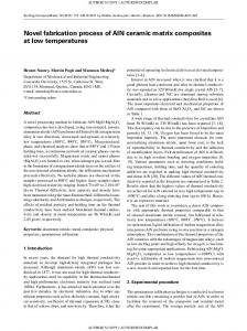
The theoretical and experimental densities of the composites with different volume fractions of filler are presented in Fig. 1. For the calculation of the theoretical values ρf and ρm are taken to be 6.02 g/cm3 and 1.14 g/cm3, respectively. The increment of the amount of filler leads to an increment of the composite density. For volume fractions up to 30 vol. %, the experimental values are approximately 90 % of the theoretical values. For higher volume fractions (40 vol. % - 60 vol. %) the experimental values represent approximately 75 % of the theoretical values. It is well known that the properties of composite materials depend to a great extent on its homogeneity. SEM images were performed to assess the degree of dispersion of the filler particles and to study the interaction between filler and matrix by means of analysing the interface. SEM images of the fracture surface of the composites are shown in Fig. 2. In the composites with 20 vol. % and 30 vol. % of BaTiO3 the particles are dispersed and distributed homogenously in the epoxy matrix (Fig. 2(a), (b)). For higher amounts of filler, the dispersion of the particles is not efficient resulting in the formation of agglomerates. The presence of residual porosity is also observed (Fig. 2(c), (d)). With respect to the interface, independently of the volume fraction of filler, the formation of an interface with weak interaction between ceramic filler and polymeric matrix is observed, as evidenced by the debonding of the particles from the matrix. Taking this into account, the higher discrepancy between the theoretical and experimental density values for composites with high volume fraction of filler (40 vol. % - 60 vol. %) shown in Fig. 1 could be explained by the presence of air voids in the composites. The electrical properties of composite materials show different trends when compared to the pure constituent phases [13]. Several mixing rules were developed to describe the relative permittivity of a system consisting on two immiscible phases. The Maxwell-Garnett model [14] considers the dielectric permittivity arising from spherical fillers dispersed in a continuous media. The Maxwell-Garnett equation can be expressed in several forms, one of those forms is shown in Eq. 4. 𝜂𝜙𝑓 (𝜀𝑓 −𝜀𝑚 )
𝜀𝑐 = 𝜀𝑚 [1 + (1−𝜙
𝑓 )(𝜀𝑓 −𝜀𝑚 )+𝜂𝜀𝑚
]
Eq. 4
𝜀𝑐 , 𝜀𝑚 and 𝜀𝑓 refer, respectively, to the relative permittivity of the composite, matrix and filler, 𝜙𝑓 is the filler volume fraction and 𝜂 is a shape factor that takes into account the geometry of the filler. 𝜂 takes a value of 3 in the case of spherical particles. 4.5
Experimental data Rule of mixtures
4.0 3.5
3
density (g/cm )
3.0 2.5 2.0 1.5 1.0 0.5 0.0 0
10
20
30
40
50
60
vol.% BaTiO3
Fig. 1. Comparison between the theoretical density obtained by the rule of mixtures and the experimental density of the composites.
4
(a)
(b)
5 µm
5 µm
(c)
(d)
5 µm
5 µm
Fig. 2. SEM images showing the fracture surface of the BaTiO3/epoxy composites with (a) 20 vol. %, (b) 30 vol. %, (c) 40 vol. % and (d) 50 vol. % of BaTiO3.
For low filler concentrations, due to the large distance between the particles, the interaction between them is weak and therefore is neglected by the Maxwell-Garnett model. Moreover, this model is only valid for low concentrations of filler [8]. At higher filler concentrations, the spontaneous polarization of the particles becomes significant because the distance between them is extremely short. Moreover, the electrical field arising from the induced dipoles is no longer negligible when calculating the field generated locally in the matrix. On the basis of this observation, Jaysundere and Smith [13] developed a more realistic mixing rule. This model considers the electric field of a dielectric sphere embedded in a continuous dielectric medium and takes into account the polarization of adjacent particles. The equation of the Jaysundere and Smith model is shown in Eq. 5. 𝜀𝑚 𝜙𝑚 +𝜀𝑓 𝜙𝑓
𝜀𝑐 =
𝜙𝑚 +𝜙𝑓
(𝜀𝑓 −𝜀𝑚 ) 3𝜀𝑚 [1+3𝜙𝑓 ] (2𝜀𝑚 +𝜀𝑓 ) (2𝜀𝑚 +𝜀𝑓 )
Eq. 5
(𝜀𝑓 −𝜀𝑚 ) 3𝜀𝑚 [1+3𝜙𝑓 ] (2𝜀𝑚 +𝜀𝑓 ) (2𝜀𝑚 +𝜀𝑓 )
The relative permittivity of the composites compared to the values predicted by the Maxwell-Garnett model and Jaysundere-Smith model as a function of the volume fraction of filler is shown in Fig. 3. For the calculation of the theoretical values, 𝜀𝑚 and 𝜀𝑓 are taken to be 6.8 and 771, respectively. Measurements were done at room temperature at a frequency of 1 kHz. From the experimental results it is possible to observe that the values of 𝜀𝑟 increase with the volume fraction of filler. 35
Experimental data Jaysundere-Smith Model Maxwell-Garnett Model
30 25
r
20 15 10 5 0 0,0 0
0,1 10
0,2 20
0,3 30
0,4 40
0,5 50
0,6 60
vol.% BaTiO3
Fig. 3. Relative permittivity 𝜀𝑟 of the composites compared to the Jaysundere-Smith Model and MaxwellGarnett Model. Measurements were done at room temperature at a frequency of 1 kHz.
5
This result is due to the increasing contribution of the BaTiO3 particles to the electric properties of the composite, since BaTiO3 has a substantially higher value of 𝜀𝑟 to that of the epoxy matrix. For a volume fraction of 60 vol. %, an increment of a factor of 3.5 is obtained when compared to pure epoxy, achieving a value of 23.8. As expected, the experimental results behave as predicted by the Maxwell-Garnett model for low concentrations of filler, up to 20 vol. %. The Jaysundere-Smith model fits well the experimental data for a filler volume fraction of up to 40 vol. %. For higher concentrations a discrepancy between the experimental data and the predicted values is observed. This discrepancy for high concentrations of filler (50 vol. % - 60 vol. %) could be explained by the presence of air voids in the composites, as seen in Fig 2. It is well known that the presence of porosity has a detrimental effect on the electrical properties of composites because of the low value of 𝜀𝑟 of air. The porosity is also expected to reduce the contact surface between composite and electrodes, therefore leading to low values of 𝜀𝑟 . The frequency dependence at room temperature of 𝜀𝑟 is shown in Fig. 4. It is possible to observe that the 𝜀𝑟 values decrease following roughly the same profile with the increment of the frequency, independently of the volume fraction of filler. Composites containing ferroelectric or conducting particles generally show this frequency dispersion phenomenon, which in turn is due to the polarization of the composites [15]. In ceramic/polymer composites two main polarizations are observed, spontaneous and interfacial polarization. The spontaneous polarization arises from the interaction between adjacent particles, whilst the interfacial polarization is produced by the dissociation of mobile charges under an electric field producing positive and negative space charges in the bulk of the composite or at the interfaces between the ceramic particles and the polymeric matrix [16]. At low frequencies, high values of 𝜀𝑟 are obtained since the induced dipoles can follow up with the changes of electric field. However, at high frequencies, some dipoles can no longer contribute to the permittivity. The interfacial polarization, which takes place at low frequencies (< 1 MHz), lags gradually behind with the increasing frequency due to the mismatching between the rate of orientation of the dipoles and the alternating electric filed, resulting in the frequency dispersion observed in Fig. 4. To induce the piezoelectricity in the ceramic phase of the composites an electric field was applied to the composites. This induced the alignment of the dipoles with the direction of the applied electric field. It is well known that the poling conditions have a major influence on the 𝑑33 of composites. Therefore, in order to understand the influence of these parameters (poling time, voltage and temperature) on the 𝑑33 , a preliminary study was done with the 30 vol. % BaTiO3/epoxy composite. The results of this optimization process are presented in Fig 5. 35
10 vol.% BaTiO3 30 vol.% BaTiO3
30
60 vol.% BaTiO3
25
r
20
15
10
5 2
10
3
4
10
10
5
10
6
10
frequency (Hz)
Fig. 4. Frequency dependence of the relative permittivity (𝜀𝑟 ) of the composites as a function of the filler volume fraction.
6
4.0
4.0 o
T = 75 C V = 10 kV
(a)
V = 3 kV V = 10 kV
3.8
3.6
3.6
3.4
3.4
3.2
3.2
d33 (pC/N)
d33 (pC/N)
3.8
3.0 2.8
3.0 2.8
2.6
2.6
2.4
2.4
2.2
(b)
2.2 10
20
30
40
50
60
20
Poling time (min)
30
40
50
60
70
80
90
100
o
Temperature ( C)
Fig. 5. Influence of the poling conditions on the d33 values of the 30 vol. % BaTiO3/epoxy composite, (a) poling time, (b) electric voltage and poling temperature.
The influence of the poling time on the 𝑑33 of the composite is shown if Fig 5(a), for this measurement the applied voltage and the poling temperature were set to be, respectively, 10 kV and 75 ˚C. The value of 𝑑33 increases from 3,1 pC/N to 3,7 pC/N when the poling time is increased from 15 min to 30 min, this value remains constant when the poling time is extended to 60 min. Given this result, the poling time of the succeeding tests was set to be 30 min. In Fig. 5(b) it is possible to observe that higher values of electric field applied lead to higher values of 𝑑33 , independently of the poling temperature. The poling temperature has also a major influence on the 𝑑33 values. Considering the results obtained for 10 kV, a maximum value of 3,7 pC/N is obtain at 75 ˚C; at 100 ˚C a drop in the 𝑑33 values is observed, resulting in a value of 2,8 pC/N. This result could be explained as follows, at 75 ˚C the Tg of the epoxy matrix is reached, which is found to be in the 60 ˚C – 70 ˚C range. At this temperature the high mobility of the induced dipoles increases the polarization of the ceramic particles, which in turn increases the permittivity and consequently the 𝑑33 values. At 100 ˚C, the mobility of the dipoles increases further but the temperature is getting close to the Curie temperature of BaTiO3, which is 120 ˚C, at this temperature the ferroelectric properties of BaTiO3 are reduced. The overall combination of these two phenomena leads to the reduction of the 𝑑33 values. Given the results obtained, the best poling conditions are 30 min, 10 kV and 75 ˚C. These conditions were applied in the poling of the remaining formulations. The accurate knowledge of the piezoelectric coefficients is essential to understand the behaviour of piezoelectric materials. The piezoelectric coefficient (𝑑33 ) is defined as the electric polarization generated in a material per unit mechanical stress applied to it. Yamada [17] developed a model able to describe the 𝑑33 of a binary system consisting on a polymeric matrix and piezoelectric particles. This model is also suitable for composites with high volume fractions of filler. The model contemplates ellipsoid particles embedded in a dielectric continuous medium. The piezoelectricity of the binary system is considered to be caused by the piezoelectric particles. The longitudinal piezoelectric coefficient of the composite (𝑑𝑐 ) is given by Eq. 6, where 𝜙𝑓 is the volume fraction of filler, 𝜃 the poling ratio, 𝐺 the local field coefficient and 𝑑𝑓 the longitudinal piezoelectric coefficient of the piezoelectric particles, which was set to be 190 pN/C. The value of 𝐺 is given by Eq. 7. 𝑑𝑐 = 𝜙𝑓 . 𝜃. 𝐺. 𝑑𝑓 𝐺 = 𝜂.Ɛ
Eq. 6
𝜂.Ɛ𝑐
Eq. 7
𝑐 +Ɛ𝑓 −Ɛ𝑐
7
𝜂 is the shape factor, 𝜀𝑐 and 𝜀𝑓 are the relative permittivity of the composite and filler, respectively. It is assumed that the piezoelectric particles exist in the continuous medium with the relative permittivity 𝜀𝑐 . The comparison of the experimental data with the Yamada model is represented in Fig. 6. There is a good agreement for composites with volume fractions of filler up to 30 vol. %, values of 𝑑33 slightly superior to those predicted by the model are obtained. However, for a further increment of the filler amount there is a discrepancy, the obtained values of 𝑑33 are lower than those predicted by the model. As observed in previous results, the presence of air voids has a negative effect on the density and relative permittivity of the composites, leading also to low values of 𝑑33 . 10
Experimental data Yamada Model
9 8 7
d33 (pC/N)
6 5 4 3 2 1 0 0
10
20
30
40
50
60
vol.% BaTiO3
Fig. 6. Comparison of the experimental data with the Yamada model for 𝑑33 values of the composites.
4.
Conclusions
BaTiO3/epoxy composites were fabricated and physical and electromechanical properties were measured aiming at the application as piezoelectric sensors to detect guided waves as a part of a structural health monitoring system to detect damage. The proposed fabrication process for the piezoelectric sensor was based on the direct mechanical mixing of filler and matrix phases, the process led to a homogenous dispersion and distribution of the filler in the matrix. A weak interfacial interaction between particles and matrix was observed in SEM images. For volume fractions of filler up to 30 vol. %, the density obtained resulted to be 90 % of the theoretical density. The values of the electromechanical properties, relative permittivity and longitudinal piezoelectric constant, obtained for volume fractions of filler up to 40 vol. % were in agreement with the theoretical models. The addition of higher amounts of filler led to particle agglomeration and formation of air voids in the composites, as demonstrated by SEM images. The presence of air voids showed to be detrimental for the density and electromechanical properties of the composites, leading to discrepancies with respect to the theoretical models. Given that the composite 30 vol. % BaTiO3/epoxy resin presented the best compromise between density and electromechanical properties, the properties of this formulation will be used as input data in FEM simulations to study the performance of BaTiO3/epoxy resin as piezoelectric transducers. The construction of a sensor pattern will be based on the analysis of differential image patterns of a structure in the pristine and damaged conditions.
8
References [1] Karbhari, V.M. 2013. Non-Destructive Evaluation (NDE) of Polymer Matrix Composites Techniques and Applications. Ed. Elsevier. [2] Rose, J.L. 2001. “A vision of ultrasonic guided wave inspection potential.” Proceedings of the Seventh ASME NDE Topical Conference. NDE 20: 1–5. [3] Giurgiutiu, V. 2007. Structural Health Monitoring with Piezoelectric Wafer Active Sensors. Ed. AP. [4] Park, J.M. et al. 2005. “Nondestructive damage detection and interfacial evaluation of single-fibers/epoxy composites using PZT, PVDF and P(VDF-TrFE) copolymer sensors.” Composites Science and Technology. 65: 241–256. [5] Su, Z., Ye, L., Lu, Y. 2006. “Guided Lamb waves for identification of damage in composite structures: A review.” Journal of Sound and Vibrations. 295: 753–780. [6] Safari, A. 1994. “Development of piezoelectric composites for transducers.” Journal de Physique III, EDP Sciences. 4(7): 1129–1149. [7] Payo, I. and Hale, J.M. 2011. “Sensitivity analysis of piezoelectric paint sensors made up of PZT ceramic powder and water-based acrylic polymer.” Sensors and Actuators A. 168: 77–89. [8] Babu, I. and de With, G. 2014. “High flexible piezoelectric 0-3 PZT-PDMS composites with high filler content.” Composites Science and Technology. 91: 91–97. [9] Dietze, M. and Es-Souni, M. 2008. “Structural and functional properties of screen-painted PZT-PVDF-TrFE composites.” Sensors and Actuators A. 143: 329–334. [10] Carponcin, D. et al. 2014. “Integrated function in a high thermostable thermoplastic PZT/PEEK composite.” Journal of non-crystalline Solids. 388: 32–36. [12] Adam, J. et al. 2014. “Ferroelectric properties of composites containing BaTiO3 nanoparticles of various sizes.” Nanotechnology. 25(6). [13] Dang, Z.M. et al. 2012. “Fundamentals, processes and applications of high-permittivity polymer-matrix composites.” Progress in materials science. 57: 660–723. [14] Maxwell-Garnett, J.C. 1904. “Colours in metal glasses and in metallic films.” Philos. Trans. Roy. Soc. Lond. 203: 385–389. [15] Banerjee, S and Cook-Chennault, K.A. 2012. “An investigation into the influence of electrically conductive particle size on electromechanical coupling and effective dielectric strain coefficients in three phase composite piezoelectric polymers.” Composites: Part A. 43: 1612–1619. [16] Kwan, C.K. 2004. Dielectric phenomena in solids with emphasis on physical concepts of electronic processes. Elsevier Academic Press. [17] Yamada, T., Ueda, T., Kitayama, T. 1982. “Piezoelectricity of a high-content lead zirconate titanate/polymer composite.” J. Appl. Phys. 53(6): 4328–4332.
9