Development of the Standard CubeSat Deployer and a CubeSat Class PicoSatellite1 Clark Turner, Computer Science Dept.
[email protected] (805) 756-6133
Jordi Puig-Suari, Aerospace Engineering Dept.
[email protected] (805) 756-6479
and William Ahlgren Electrical Engineering Dept.
[email protected] (805) 756-2309
California Polytechnic State University San Luis Obispo, CA 93407 Abstract—Cal Poly students are participating in the development of a new class of picosatellite, the CubeSat. CubeSats are ideal as space development projects for universities around the world. In addition to their significant role in educating space scientists and engineers, CubeSats provide a low-cost platform for testing and space qualification of the next generation of small payloads in space. A key component of the project is the development of a standard CubeSat deployer. This deployer is capable of releasing a number of CubeSats as secondary payloads on a wide range of launchers. The standard deployer requires all CubeSats to conform to common physical requirements, and share a standard deployer interface. CubeSat development time and cost can be significantly reduced by the development of standards that are shared by a large number of spacecraft.
OPAL mission4. CubeSats are constrained to a 100 mm cube with a mass of one kilogram or less. Led by Stanford University’s Space Systems Development Lab (SSDL), the CubeSat project is developed jointly by universities and industry worldwide.
TABLE OF CONTENTS
One of the main objectives of the CubeSat program is the development of a new class of standardized picosatellites. The CubeSats’ size and mass standards, 100 mm cube and 1 kg respectively, are developed as an extension of the picosatellites deployed by Stanford’s OPAL spacecraft. The CubeSats’ dimensions are large enough to provide significant power through the use of body mounted solar cells. Moreover, the CubeSats’ mass is large enough to carry a significant payload given current developments in small and efficient sensors, processors and communications equipment.
1. 2. 3. 4. 5. 6. 7.
INTRODUCTION STANDARDIZATION BY DEPLOYER MECHANISM POLYSAT: CAL POLY’S PROTOTYPE CUBESAT FUTURE ADVANCES CONCLUSION ACKNOWLEDGMENTS REFERENCES
CubeSat developments at the California Polytechnic State University (CalPoly) are twofold: first, develop the standardized launcher-interface/deployer mechanism for CubeSats, and second, demonstrate the feasibility of developing a working CubeSat using low-cost, commercial off-the-shelf components. The project involves a multidisciplinary team of software, aerospace, manufacturing, electrical, and mechanical engineering undergraduate students.
2. STANDARDIZATION BY DEPLOYER MECHANISM
1. INTRODUCTION Recent years have seen an increase in the number of student satellites developed at universities around the world1,2. To date, most university satellites require several years to develop and significant financial resources, making them prohibitive for small programs. New technological developments in small low-power electronics make smaller, lower-cost satellites feasible. The CubeSat program intends to develop a picosatellite standard that significantly reduces the cost and development time of student satellites. In addition, CubeSats can serve as facilities for in-space experimentation, as well as a means of space-qualifying future small-satellite hardware3. The CubeSat standard is an evolution of the picosatellites developed for Stanford’s 1
0-7803-6599-2/01/$10.00 2001 IEEE
Beyond the initial form factor and mass of the CubeSats, additional standard features are determined by the need to interface the spacecraft with a standard deployment system. The CubeSat deployer must satisfy a number of requirements: •
The deployer must protect the launch vehicle and primary payload from any mechanical, electrical or electromagnetic interference from the CubeSats even in the event of a catastrophic CubeSat failure.
•
The CubeSats must be released from the deployer with minimum spin and a low probability of collision with the launch vehicle or other CubeSats.
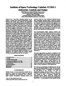
Figure 1 - P-POD Deployer with rail detail
•
The deployer must have the ability to interface with a variety of launch vehicles with minimum modifications and with no changes to the CubeSat standard.
•
The mass of the deployer should be kept to a minimum.
•
The deployer should incorporate a modular design that allows different numbers of CubeSats to be launched on any given mission.
•
The resulting CubeSat standard should be easily
manufactured without using exotic expensive construction techniques.
materials
and
The Poly Picosatellite Orbital Deployer (P-POD) shown in Fig. 1 is the result of a lengthy development process by CalPoly students to satisfy the requirements above. The tube design produces a reliable linear course for the CubeSats without significant spin. This deployment method was successfully demonstrated in the Opal mission. However, the P-POD deployer is different in that it does not have a mechanism to lock the CubeSats inside the tube. This reduces the chances of CubeSats jamming inside the tube and failing
Figure 2 - P-PODs in a 3x3 Configuration
to deploy. On the other hand, shock and vibration loads may increase. Shock and vibration tests on a prototype deployer will be used to determine the extend of this problem. The standard P-POD deployer contains 3 CubeSats although the design could be lengthened to fit a larger number of CubeSats. In addition, the P-POD’s design allows a number of deployers to be mounted together on a launch vehicle as shown in Fig. 2. During the deployment sequence the CubeSats ride on rails built into the corners of the tube (see Fig. 1) and a simple spring provides the force to push the CubeSats out of the deployer with a linear velocity of approximately 0.3m/s. Deployment is initiated by the release of the PPOD’s spring loaded door using a G & H Technologies cable release actuator. The P-POD is constructed using 7075-T6 Aluminum due to this material’s high strength, ease of manufacture and relative low cost. The deployer is designed to sustain 15g loads resulting in a total P-POD mass of approximately 1.5 kg. The tube provides an enclosure strong enough to handle the structural failure of one of the CubeSats while providing a Faraday cage to protect the primary payload from electromagnetic interference. Given the P-POD’s design, a final set of standards for the CubeSats can be developed. A CubeSat specification drawing is shown in Fig. 3. In addition to the basic size and mass requirements some standard requirements are introduced by the deployer. This include: •
The CubeSat needs 8.5 mm clearance on the four side edges, which will be used to slide along the internal rails of the deployer (Figure 1).
•
Eight 7 mm standoffs on the top and bottom faces of the CubeSat are required to provide separation between CubeSats.
•
On top of each side, excluding space for the rails and standoffs, an additional 6.5 mm space is available to accommodate solar panels, antennas, or other components extending beyond the 100mm limit.
•
A minimum of one kill switch is required in the standoffs on the top plate (Figure 3) to ensure that none of the CubeSats are active during launch. Along with the kill switches there is also a requirement for a “remove before flight” pin, to deactivate the CubeSat during shipping and loading.
•
An optional data port can be included in the design in order to complete last minute check or to charge internal batteries after the CubeSat is loaded into the deployer.
3. POLYSAT: CAL POLY’S PROTOTYPE CUBESAT The Cal Poly prototype CubeSat, PolySat, meets the deployer’s constraints for size, mass, shape, and interface. The purpose of our prototype is twofold: first, to validate the deployer standard design and second, to demonstrate that CubeSats provide a viable platform for basic experiments in space. PolySat is a minimum configuration satellite, consisting of a simple set of commercial-off-the-shelf components to demonstrate low-Earth orbit operation. PolySat’s structure is consistent with the deployer’s standard. A 100 mm cube has been designed with the required guiderails and interfaces for the deployer. The structure is made of aluminum 7075-T6, with a mass of approximately 0.3 kg and strong enough to survive launch loads. Electronic trays and battery supports are located inside the satellite and contribute to the structural integrity of the spacecraft. Mounting points for antennas are located on the exterior of the satellite. The antennas are rolled around the satellite before deployment and held in place with monofilament secured using a short length of nichrome wire inside the spacecraft. Upon deployment, a current is passed through the nichrome wire, which heats and melts the monofilament and releases the antennas. The communications system consists of a downlink transmitter, an uplink receiver, and independent antennas for each. Downlink is provided by a modified on-board Alinco DJ-C4T 440 MHz amateur radio transmitter. This is commercially available for $70 retail, and offers 300 mW output, at a cost of 1.11 W when transmitting. It is very robust, compact, and has low idling power requirements. FCC amateur-radio regulations demand an independent uplink receiver capable of providing a minimum of an "off" command for the downlink transmitter. Requirements analysis revealed that commonly available amateur radio receiving equipment would likely suffer from overload and serious intermodulation distortion (IMD) from strong earth generated signals on nearby frequencies. This problem was solved by using a MICRF004 "data receiver on a chip" (commonly used for garage door opener receivers) from Micrel, Inc. This solution is quite cheap to implement at about $30. It is easily modified to receive in the 144 MHz amateur radio band with extremely low power requirements and low sensitivity. Low sensitivity, usually a disadvantage, affords the Cubesat uplink receiver relative immunity to spurious signals. Compensation is easily provided on earth by increased amplification and antenna gain with commonly available amateur radio components. This receiver choice enables future enhancements for the uplink channel such as reset command or even simple reprogramming of the onboard processor. Independent dipole antennas mounted on one face of the box provide the downlink and uplink capability. The antenna design mirrors the technique used on OPAL, namely metal "measuring tape" available at any hardware store. It is flexible, holds its shape well and has served as adequate material on previous university-satellite missions.
Amateur radio frequencies (and licenses) are used for low cost and a readily accessed base of experience. In addition to inexpensive, commonly available equipment, there exists a large network of amateur radio operators with well-equipped ground stations available to assist in our mission. This is a tremendous advantage for a small startup group of undergraduate students. Command is provided by an Atmel BasicX PIC microcontroller running custom software, written for the project. This chip provides 8 digital and 8 analog lines for I/O. The processor activates the transmitter at required intervals for downlink tasks. The FCC required identification of the transmitter is given in Morse code
Figure 3 - CubeSat specification drawing.
Figure 4 - PolySat with deployed antennas
using tone modulated FM under the call sign “N6CP” (Cal Poly’s Amateur Radio Club) followed by mission specific data. The data is encoded using dual tone multi frequency (DTMF) tones by the processor. The transmitter is keyed by the processor at specified intervals while the encoded data is passed to the audio input for transmission. The use of DTMF encoding involves a relatively slow rate of data transfer but increases the simplicity and reliability of the link. This can be important if the spacecraft experiences a lose gain or increased noise on the downlink frequency. Currently, sensors being considered for PolySat include thermistors to measure the temperature of the structure and key components as well as a voltage and current sensor for the batteries. Power is provided by two on-board battery packs consisting of two primary lithium-ion batteries each. Step-
down converters are used to provide 5V to the computer and receiver and 3.7V for the transmitter. This battery pack provides 209 watt-hours using four cells of 116g each. This represents approximately 150 hours of transmitting time. PolySat uses passive thermal control, using coatings and paints to control heat radiation and absorption. Operating range is expected to be -40º C to 70º C. As described, the PolySat spacecraft is well under the 1kg mass constraint. A preliminary mass and power budget for the spacecraft is shown in Table 1. When in orbit the spacecraft will function as a beacon transmitting data from the on-board sensors at specified intervals. The data will be received by amateur radio operators around the world. The spacecraft is expected to operate for several weeks given a low transmitting duty cycle. Note that about 200g of mass are currently available for contingencies or additional payload.
Table 1. Mass and Power for PolySat Component Transmiter
Mass 16 g
Receiver Microcontroller Thermistor Voltage Sensor Structure Batteries Total
5g 10 g