PHYSICAL REVIEW SPECIAL TOPICS - ACCELERATORS AND BEAMS 17, 083501 (2014)
Development of vertical electropolishing process applied on 1300 and 704 MHz superconducting niobium resonators F. Eozénou,* Y. Boudigou, P. Carbonnier, J-P. Charrier, Y. Gasser, L. Maurice, F. Peauger, D. Roudier, and C. Servouin CEA, Irfu, SACM, Centre de Saclay, F-91191 Gif-Sur-Yvette, France
K. Muller Phelma–Grenoble INP–38016 Grenoble Cedex 1, France (Received 7 March 2014; published 21 August 2014) An advanced setup for vertical electropolishing of superconducting radio-frequency niobium elliptical cavities has been installed at CEA Saclay. Cavities are vertically electropolished with circulating standard HF-HF-H2 SO4 electrolytes. Parameters such as voltage, cathode shape, acid flow, and temperature have been investigated. A low voltage (between 6 and 10 V depending on the cavity geometry), a high acid flow (25 L= min), and a low acid temperature (20°C) are considered as promising parameters. Such a recipe has been tested on single-cell and nine-cell International Linear Collider (ILC) as well as 704 MHz five-cell Super Proton Linac (SPL) cavities. Single-cell cavities showed similar performances at 1.6 K being either vertically or horizontally electropolished. The applied baking process provides similar benefit. An asymmetric removal is observed with faster removal in the upper half-cells. Multicell cavities (nine-cell ILC and five-cell SPL cavities) exhibit a standard Q0 value at low and medium accelerating fields though limited by power losses due to field emitted electrons. DOI: 10.1103/PhysRevSTAB.17.083501
PACS numbers: 74.70.Ad, 81.65.Ps, 82.47.Wx, 82.45.Qr
I. INTRODUCTION Electropolishing in hydrofluoric-sulfuric acid mixtures has become the reference process to reach high performance on niobium cavities [1] in accordance with the requirements of recent projects such as Continuous Electron Beam Accelerator Facility upgrade [2], X-ray Free Electron Laser linac [3], and future International Linear Collider (ILC). According to the standard process, the cavity is electropolished in a horizontal position, while rotating and half filled with circulating acid. Vertical electropolishing (VEP) is studied in some laboratories as an alternative [4–10]. The aim is to develop an easier process compared to horizontal electropolishing (HEP), while providing similar performance, in order to achieve a cost-effective production of cavities for upcoming largescale projects in the near future. As an example, the construction of the ILC requires the treatment of 16 000 cavities for the 500 GeV baseline configuration. High gradients have already been achieved by VEP with stirred static acid [11,12] but only for final thin removal; for deeper removal a Q slope is observed [12]. We anticipate that a circulation of the acid mixture and a better acid *
renewal should provide improved electropolishing conditions. An automated VEP device with a circulating acid system has been developed at CEA Saclay (see Fig. 1). The cavity is filled from the bottom and the acid runs back to the tank by gravity from the top of the setup. The technical
[email protected]
Published by the American Physical Society under the terms of the Creative Commons Attribution 3.0 License. Further distribution of this work must maintain attribution to the author(s) and the published article’s title, journal citation, and DOI.
1098-4402=14=17(8)=083501(9)
083501-1
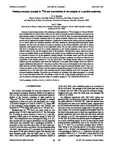
FIG. 1. Five-cell SPL cavity during VEP treatment.
Published by the American Physical Society
F. EOZÉNOU et al.
Phys. Rev. ST Accel. Beams 17, 083501 (2014)
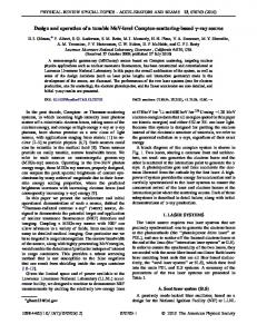
characteristics of this setup are detailed elsewhere [5]. It has been designed for the treatment of elliptical cavities, from 1.3 GHz single-cellto 704 MHz five-cell cavities designed for the Superconductive Proton Linac (SPL) [13]. As a first step, single-cell Tesla-shaped cavities have been used to commission the setup and optimize the parameters. Then, multicell (SPL five-cell and ILC ninecell) cavities have been electropolished. Results will be presented for these 1300 and 704 MHz superconducting niobium resonators. II. PARAMETERS STUDY ON SINGLE-CELL 1300 MHZ TESLA-SHAPED CAVITY Vertical electropolishing at a voltage of 20 V has already been investigated on single-cell cavities [5], and a gradient of 30 MV=m has been achieved. In a second step, single-cell cavities have been electropolished with parameters derived from standard horizontal EP: (i) moderate acid flow (8 L= min); (ii) voltage above 12 V; (iii) temperature around 30° C.The electrolyte is a mixture of HFð40w%Þ − H2 SO4 ð96w%Þ in volume proportions of 1 to 9. The cathode chosen for these experiments consists in a rod shape with a small protuberance (20 mm in length and 50 mm in diameter). This cathode is used in [5]. We applied those parameters to the single-cell Teslashaped cavity “1AC3.” The inner surface inspection was performed and revealed that these parameters are not compatible with proper electropolishing conditions. In fact, the surface is deteriorated after 70 μm removal on average: a ring of pits is observed between the equator and iris of the upper half-cell (see Fig. 2). The local removal rate is above 1 μm=min. It is too high for desirable electropolishing conditions, if considering the appropriate rate is 0.6 μm=min for HEP. The location of pits coincides with a singularity of the fluid distribution modeled at low fluid velocity which will be mentioned later in Fig. 7. Furthermore, the presence of hydrogen bubbles insufficiently evacuated by the acid flow might also amplify this phenomenon. Thickness measurements using an ultrasonic gauge were carried out, at six locations of the cell [Fig. 2(c)]. The gauge was calibrated using a niobium plate. At one location, the spans can be explained by the nonflatness of the cavity and therefore, an uncertainty is introduced while positioning reproducibly the sensor. The removal on the upper or lower half-cell is well illustrated in Table I. As a consequence, we decided to increase the acid flow up to 25 L= min in the following VEP sequences so as to improve the fluid distribution (symmetry in the cell) and the hydrogen evacuation out of the cavity. This would allow both efficient acid renewal and temperature control (electrolyte at 20° C) inside the cavity. Nitrogen is also blown in the acid tank and at the top end group of the cavity in order to prevent any explosion risk and to favor the
FIG. 2. (a) Inspection of the inner surface of “1AC3” cavity after VEP at 12 V − 30° C. A ring of pits observed at the location indicated by a red arrow on (b). For further study of material removal, single-cell cavities were carved at six locations according to (c).
removal of the gas generated during the process. Previous EP investigations showed that a reduced electropolishing voltage (down to 5 V) has no influence on cavity performance (a process called “low-voltage electropolishing”) [14]. We decided to apply low-voltage VEP with the following expectations: (i) a decreased joule heating and decreased temperature gradient in the cavity and (ii) reduced parasitic electrochemical reactions as sulfur forms [14–17]. A higher acid flow rate is thus expected to provide improved electropolishing conditions. The highlighted set of parameters was applied on the single-cell Tesla-shaped cavity “1DE1,” which was previously horizontally electropolished, in order to compare the two techniques. After 70 μm additional VEP, the achieved surface is very shiny. The average removal rate is 0.2 μm= min. No pitting is observed though shallow stripes are observed at the equator area in the upper half-cell. The new set of parameters seems promising and the performance of the cavity at 1.7 K will be evaluated.
TABLE I. Measured material removal at 6 locations in the cavity at 6 V and 8 L= min acid flow rate. Fluid circulates from bottom.
083501-2
Average removal (μm)
100
Removal at location #1 #2 #3 #4 #5 #6
80–90 50 60–70 80–100 160–180 210–240
DEVELOPMENT OF VERTICAL ELECTROPOLISHING …
Phys. Rev. ST Accel. Beams 17, 083501 (2014)
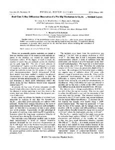
FIG. 4. Radio-frequency results of the “1AC3” cavity at 1.6–1.7 K after VEP sequences at 6 V and baking. FIG. 3. Radio-frequency results of the “1DE1” cavity at 1.6–1.7 K before/after VEP at 6 V. The baking process has been performed at 137° C during 60 h.
III. RESULTS ON 1300 MHZ CAVITY WITH OPTIMIZED PARAMETERS
allows one to reach gradients similar to those obtained with standard horizontal EP treatment. The decrease in Q0 after the last VEP treatment on the 1AC3 cavity is not understood yet. B. Results on a ILC nine-cell cavity
A. Results on single-cell cavities The performance of the 1DE1 as received (after HEP) was very high (Eacc > 42 MV=m, high Q0 ). It was tested at 1.6–1.7 K after the additional 70 μm low-voltage VEP sequence. The cavity was rinsed with diluted hydrofluoric acid before the presented test in order to remove possible contamination resulting from a leak. The rf tests in vertical cryostat were performed before and after baking at 137° C during 60 h. Q0 ¼ fðEaccÞ plots are shown in Fig. 3. The following results can be observed: (i) the baking effect is similar compared to HEP: the Q slope at high field is removed and the performance was limited by quench at Eacc > 40 MV=m; (ii) the Q0 ¼ fðEaccÞ plots after HEP and after VEP agree very well. Low-voltage VEP offers similar performance compared to HEP. In a second step, we intend to achieve similar performance with a cavity that has been exclusively electropolished. Additional tests were carried out on the 1AC3 cavity. The 1AC3 cavity, as described in Fig. 2, was again electropolished according to two VEP sequences with “optimized” parameters and baked under vacuum (110°C × 60 h). After each sequence, it was tested at 1.6 K (see results in Fig. 4). The gradient reached 35 MV=m gradient, in spite of the pitted surface. The performances were limited by a quench located at the pitted area with both thermal sensors and oscillating superleak transducers. Moreover the gradient was improved after additional VEP sequence at low voltage, though the Q0 value was degraded. The presented preliminary results on Tesla-shaped single-cell cavities show that the described VEP treatment offers potentials similar to the standard HEP. A Q slope is observed after VEP, which is removed by baking. VEP
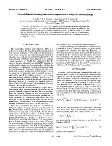
The same set of parameters (6 V − 20 L= min − T < 20° C) was applied on a nine-cell cavity: 50 μm on average were removed from the “TB9R1025” ILC cavity from Fermi Accelerator National Laboratory (FERMILAB), previously horizontally electropolished. A large cathode diameter (50 mm) was used for nine-cell VEP experiments in [5] in order to decrease the anodic current density. The diameter was reduced down to 40 mm for this experiment in order to avoid contact with HOM antennas during insertion. Unfortunately, the performance was limited by field emission, with onset at 15 MV=m. The Q0 value at low and medium fields is satisfactory (see Fig. 5). Additional VEP sequences and cleanroom assembly are planned for improvement.
FIG. 5. Radio-frequency results of the “TB9R1025” ILC cavity at 1.7–1.8 K after HEP þ 50 μm VEP at 6 V.
083501-3
F. EOZÉNOU et al.
Phys. Rev. ST Accel. Beams 17, 083501 (2014)
FIG. 6. (a) Cathode used in previous VEP experiments (shape #1) and (b) optimized shape (shape #2).
IV. CATHODE DESIGN AND ASYMMETRY OF THE PROCESS
FIG. 8. IðVÞ curves plotted on single-cell cavity with cathode shape #1 & #2.
A. Alternative cathode shapes The possible benefits of alternative cathode shapes have been widely investigated [7–9,18–22]. The effectiveness of an optimized electrical field in the case of the buffered electrochemical polishing treatment (electrolyte involving additional acid lactic) [23] has been demonstrated [7]. Alternative shapes have been proposed in order to improve the homogeneity of the process. We have decided to focus on cathode shapes compatible with an easy insertion in the cavity (narrower than the diameter of the beam pipe). The work done in [5] was pursued with a more exhaustive study [22]: a design of experiment method was carried out using COMSOL software in order to obtain both uniform electric field and fluid distribution inside the cell. Dominant parameters that have been put forward are (i) the shape of the cathode (ellipsoid or cylindrical) and (ii) the length and diameter of the protuberance. The optimized cathode is shown in Fig. 6(b) (shape #2). Its shape is a cylinder (70 mm in diameter and 70 mm in length). Figure 7 shows the fluid distribution inside the cell at low flow rate ( 41 MV=m) limited by quench. VEP with
083501-7
F. EOZÉNOU et al.
Phys. Rev. ST Accel. Beams 17, 083501 (2014)
circulating acid is promising at least for final treatment after bulk EP/tumbling, etc. Another cavity reaches 36 MV=m after heavy removal by VEP in spite of a pitted initial surface. The baking effect after VEP is similar to HEP. Nice surface finishing as well as a standard Q0 value are obtained at low/medium fields on a nine-cell 1300 MHz cavity. Unfortunately, the performance of the tested cavity was limited by field emission. An asymmetric removal is observed with faster removal in the upper half-cells. The configuration is more challenging in the case of 704 MHz cavities because of the larger volume of hydrogen to be generated. A deficient evacuation of this hydrogen is responsible for a faster attack in the upper cell, and pitting of the surface. A five-cell SPL cavity with β ¼ 1 has been vertically electropolished with a rod cathode. Thanks to cavity turning between sequences, a symmetric material removal in the cavity is achieved. No significant modification of the field flatness is observed after each VEP sequence, once the hydrogen flow is evacuated properly. The cavity has been tested at 1.5 K and showed heavy Q disease (100 K effect).Heat treatment at 650° C allowed recovery of the expected Q0 value. The gradient is presently limited to 18 MV=m because of the radiation level. The VEP treatment of five-cell 704 MHz cavities for the Europeen Spallation Source with β ¼ 0.86 will also be investigated. These cavities differ from the SPL cavity with straight beam pipes (no taper), which should facilitate the fluid circulation. Besides, improvements of the existing machine are planned in order to improve gaseous evacuation during VEP treatments. They consist in enclosing the cathode with a meshed net in Teflon and in increasing the volume of the upper end group of the setup. ACKNOWLEDGMENTS We acknowledge the support of the European Community-Research Infrastructure Activity under the FP7 program (EuCARD, Contract No. 227579). This work has been carried out with the financial support of the “Conseil General de l’Essonne” in the frame of the ASTRE program. This work was possible thanks to Dr. C. Ginsburg from FERMILAB who provided the ILC cavity and Dr. D. Reschke from DESY for the loan of the 1DE1 Tesla single-cell cavity. We are also grateful to Dr. S. Calatroni and A. Mongelluzzo who made the heat treatment of the SPL cavity possible at CERN. We thank Dr. C. Madec for fruitful comments and proofreading of this work.
[1] K. Saito et al., in Proceedings of the 8th Workshop on RF superconductivity (SRF 1997), AbanoTerme (Padova), Italy, 1997, edited by V. Palmieri (INFN, Padova, Italy,1998), pp. 795–813. [2] A. Burrill et al., in Proceedings of the 2nd International Particle Accelerator Conference, IPAC-2011, San Sebastián, Spain (EPS-AG, Spain, 2011), MOOCA01, pp. 26–28.
[3] D. Reschke, in Proceedings of the 15th International Workshop on RF Superconductivity (SRF 2011), Chicago, 2011, edited by M. Power, (JAcOW, 2012), MOIOA01, pp. 2–6. [4] R. L. Geng et al., in Proceedings of the 12th International Workshop on RF Superconductivity (SRF 2005), Cornell University, Ithaca, NY, 2005, edited by S. Bolomestnykh, M. Liepe, and H. Padamsee (LEPP, Cornell University, Ithaca, NY, 2007), THP04, pp. 459–463. [5] F. Éozénou, S. Chel, Y. Gasser, C. Servouin, B. Visentin, J-P. Charrier, and Z. Wang, Phys. Rev. ST Accel. Beams 15, 083501 (2012). [6] S. Calatroni et al., in Proceedings of the 25th Linear Collider Conference (LINAC 2010), Tsukuba, Japan, 2010, edited by H. Sako (JAcOW, 2011), THP032, pp. 824–826. [7] S. Jin, A. T. Wu, X. Y. Lu, R. A. Rimmer, L. Lin, K. Zhao, J. Mammosser, and J. Gao, Appl. Surf. Sci. 280, 93 (2013). [8] K. Nii et al., in Proceedings of the 16th International Workshop on RF Superconductivity (SRF 2013), Paris, France, 2013, edited by G. Martinet (IN2P3, Paris, 2014), TUP052, pp. 524–530. [9] L. M. A Ferreira et al., in [8], TUP047, pp. 512–514. [10] F. Furuta et al., in [8], TUP049, pp. 518–520. [11] Z. A. Conway et al., in Proceedings of the 14th International Workshop on RF Superconductivity (SRF 2009), Berlin, Germany, 2009, edited by M. Abo-Bakr, B. Kuske, A. Liebezeit, S. Voronenko, and V. Schaa (SRF, Berlin, 2009), TUPPO004, pp. 176–179. [12] F. Furuta et al., in Proceedings of the 3rd International Particle Accelerator Conference, New Orleans, LA, 2012 (IEEE, Piscataway, NJ, 2012), TUPPR045, pp. 1918–1920. [13] J. Plouin et al., in Proceedings of the 15th International Workshop on RF Superconductivity (SRF 2011), Chicago, 2001, edited by M. Power (JAcOW, 2012) MOPO034, pp. 157–161. [14] F. Eozenou et al., Phys. Rev. STAccel. Beams 13, 083501 (2010). [15] K. Saito et al., in Proceedings of the 4th Workshop on RF Superconductivity (SRF 1989), Tsukuba, Japan, 1989, edited by Y. Kojima (National Laboratory for High-Energy Physics (KEK), Tsukuba, Japan, 1990), pp. 635–694. [16] A. Aspart, F. Eozénou, and C. Antoine, Physica (Amsterdam) 441C, 249 (2006). [17] P. V. Tyagi, M. Nishiwaki, T. Saeki, M. Sawabe, H. Hayano, T. Noguchi, and S. Kato, J. Vac. Sci. Technol. A 28, 634 (2010). [18] S. Calatroni et al., in Proceedings of the 11th workshop on RF superconductivity (SRF 2003), edited by D. Proch (DESY, Hamburg, 2004). [19] M. Bruchon et al., in Proceedings of the 13th International Workshop on RF Superconductivity (SRF 2007), Beijing, China, 2007, edited by J. Hao, S. Huang, and K. Zhao (Peking University, Beijing, China, 2009), TUP51, pp. 247–250. [20] N. Steinhau-Kühl et al., in [19], TUP33, pp. 204–206. [21] F. Eozenou et al., in [8], TUP046, pp. 508–511. [22] K. Muller, CEA internal report, 2012. [23] A. T. Wu, J. Mammosser, L. Phillips, J. Delayen, C. Reece, A. Wilkerson, D. Smith, and R. Ike, Appl. Surf. Sci. 253, 3041 (2007).
083501-8
DEVELOPMENT OF VERTICAL ELECTROPOLISHING … [24] H. Tian and C. E. Reece, Phys. Rev. ST Accel. Beams 13, 083502 (2010). [25] H. Tian, S. G. Corcoran, C. E. Reece, and Michael J. Kelley, J. Electrochem. Soc. 155, D563 (2008). [26] F. Eozenou et al., in CARE Report No. 06-10-SRF, 2006, CEA. [27] A. Chandra, M. Sumption, and G. S. Frankel, J. Electrochem. Soc. 159, C485 (2012).
Phys. Rev. ST Accel. Beams 17, 083501 (2014)
[28] L. M. A. Ferreira (private communication). [29] TTC-Report 2008-05, http://flash.desy.de/sites/site_vuvfel/ content/e403/e1644/e2271/e2272/infoboxContent2354/ TTC‑Report2008‑05.pdf. [30] B. Bonin and R. W. Roth in Proceedings of the 5th International Workshop on RF Superconductivity, Hamburg, German, 1991, edited by D. Proch (DESY, Hamburg, 1992), p. 210.
083501-9