Development of Wireless Power Transfer using Inductive Approach to Power Up Multiple Low Power Devices S. Saat, C.S.Hui, F. K. A. Rahman, Y. Yusop, S. H. Husin Advanced Sensors and Embedded System Research Group (ASECs), Faculty of Electronic and Computer Engineering, Universiti Teknikal Malaysia Melaka (UTeM), Malaysia.
[email protected]
Abstract—Wireless power transfer (WPT) is a technology that implements non-contact power transmission within a distance. There are three types of wireless power transfer, which are inductive power transfer (IPT), capacitive power transfer (CPT), and acoustic power transfer (APT). Among these three types of wireless power transfer, the inductive power transfer has advantages in term of the transmission distance and high efficiency. Therefore, we focused on the inductive power transfer to develop a wireless charging to power up multiple low power devices. In this work, we implemented the IPT method to power up multiple devices on the office table. This IPT system enabled the power transmission from the office table to the several loads that has been attached together with the receiver coil. Hence, electronic appliances such as table clock and desk lamp (used in this work) will operate without using a wire to get a power source from power outlet or a battery. To be more specific, in this work, a high efficiency Class-E converter was designed to convert the DC source into AC. Through this, the efficiency of the system can be improved. Finally, the developed prototype was able to power up desk lamp and digital clock wirelessly with 70% efficiency. The performances analysis of the developed prototype is discussed and the future recommendation of this technique is also presented in this paper. Index Terms—Wireless Power Transfer; Class E Inverter; Inductive Approach; Multiple Devices.
I. INTRODUCTION Nowadays, people use electrical appliances and electronic devices to make their daily life easier. To operate these appliances and devices, most of them need to be powered up by batteries. As the technology advances, the usage of wired appliances has been invented into wireless operating devices. However, they still need to be recharged so that they can be operated with sufficient power. In this case, Wireless Power Transfer (WPT) technology has been introduced to solve the problems of wired appliances. Based on its advantages [1], this type of power transmission is an attractive research area to be explored as this advancement will allow users to recharge their electronic devices wirelessly, allowing flexibility of their movements. Wireless power transfer was introduced by Nikola Tesla several decades ago [2]. In his trial, he tried to light up 200 bulbs and run an electric motor over 25 miles wirelessly.
There are various advantages of using wireless power transfer as a power transmission, as discussed in [1]. Some of them are: Avoid electrical shock and sparking fire that is common with the wired appliances as wireless power transfer implements non-physical contact between the power supply and load. Give flexibility of movement for the load that needs to be powered up. The need to place the load at one station while it is being recharged limits the flexible movement of the load. Create messiness due to the arrangement of the multiple device in a multiple socket. Wireless power transfer can overcome this problem by making the multiple devices become neat and tidy. Besides, wireless power transfer technology has been practiced widely in charging application systems. This wireless power transfer can be implemented in two types of charging system, which are low power applications and high power applications. There are some popular electronic devices that implement the concept of wireless power transfer to operate in our daily life. For example, Sonicare electrical toothbrush by Philips, as shown in Figure 1 needs to be recharged after being used for a certain time. This product has its own charging station that is operated as a transmitter while the toothbrush itself will be operated as the receiver. The toothbrush is equipped with a receiving coil on the source cradle to start the charging process [3].
Figure 1: Sonicare Toothbrush
The other machine that uses the wireless power transfer concept is the power mat that can power up our mobile devices when they are placed on it, as shown in Figure 2. It offers wireless charging system that will eliminate the usage of wires in charging processes. The charging system also
ISSN: 2180 – 1843 e-ISSN: 2289-8131 Vol. 8 No. 5 May – August 2016
111
Journal of Telecommunication, Electronic and Computer Engineering
offers charging operation that allows the electronic device to be recharged as long as the source resonator is aligned with the device resonator [4].
Figure 2: Power Mat by WiTricity
In general, wireless power transfer can be divided into several sections. As we focused on near-field technologies, there are three types of the wireless power transfer, which are the capacitive coupling, inductive coupling and the acoustic coupling. As shown in Figure 3, the capacitive coupling uses electric field to transmit energy from the transmitter to the receiver. The channel for the transmission part is a copper plate that is placed in a parallel form. From the transmitter part, an alternating voltage will be generated and then will be induced to the receiver part by the electrostatic induction [5]. The transmission of the power can still be produced as long as the copper plate is in the range of distance provided.
power would be transmitted in the form of wave from the transmitter to the receiver [7]. The power generated at the transmitter side will be converted into the sound energy using the AC/DC converter. The converted power will then be transmitted using the transducer. The receiver will receive the transmitted energy from the transmitter part using the transducer. That energy will be converted back to the electrical energy before it can be supplied to the load. On the other hand, there is another type of power transfer that transmits power using optical power. It uses a laser diode to create an optical power beam and photovoltaic diode to convert that power into electrical signal to be transmitted to the receiver [11].
Figure 5: Acoustic power transfer technology
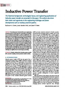
II. METHODOLOGY The block diagram shown in Figure 6 summarizes the methodology used in this work.
Figure 3: Capacitive coupling configuration
The other type of wireless power transfer is the inductive coupling. According to Covic and Boys, the inductive power transfer has been an active research topic for engineering studies for the past 30 years [10]. In contrast to the capacitive coupling, this type of power transmission uses two coils that is placed in an opposite way in order to make the power transmitted. In this type of coupling, the transmitter part will generate an alternating voltage in order to be transmitted by the transmitter coil. The power will be transmitted in the form of a magnetic field. The magnetic field is created based on the coil configuration on the primary and secondary part [6]. Figure 4 illustrates the concept of this inductive power transfer approach.
Figure 4: Inductive coupling configuration
The other Wireless Power Transfer that is popular as a power transmission method is the acoustic power transfer. This type of power transfer is shown in Figure 5. This acoustic power transfer makes a transmission through vibration. The 112
Figure 6: Methodology of the Project
Based on Figure 6, this work is divided into two parts, which are the transmitter and receiver parts. The power is transferred from the transmitter to the receiver through the transmission coils. For the transmitter part, it consists of PIC, MOSFET driver, class E inverter and transmitter coil. A Peripheral Interface Controller (PIC) was used to generate a pulse width modulation (PWM) with the frequency of 1MHz and 50% duty cycle. Since the voltage of the pulse generated by PIC was 5V and it was unable to trigger the MOSFET in class E inverter, a MOSFET driver was used to increase the voltage to a level that can trigger the MOSFET. After that, a class E inverter was used to convert the direct current (DC) source to alternating current (AC) source at high frequency with high efficiency. Besides that, it was also used to improve the efficiency of this project due to low switching losses. The voltage supply of PIC, MOSFET driver and class E inverter were 5VDC, 9VDC and 12VDC respectively. Other than that, the receiver part includes receiver coil, rectifier and load. The function of rectifier circuit is to convert the AC source back to DC source. Since, there were two loads applied in this project, each load required their own dedicated rectifier circuit. As a result, two rectifiers were designed separately based on the specification of the load. The detailed design for every part in this project is described in following
ISSN: 2180 – 1843 e-ISSN: 2289-8131 Vol. 8 No. 5 May – August 2016
Development of Wireless Power Transfer using Inductive Approach to Power Up Multiple Low Power Devices
section. A. Pulse Width Modulation (PWM) The function of pulse width modulation in transmitter part is to supply AC signal to the gate at MOSFET. The PIC18F4550 was used as one of the tools to generate the square waveform at 1 MHz frequency and 50% duty cycle. This frequency is very optimal for Class E since the rate of losses occurred at 1MHz frequency was very low compared to higher frequency. This is because the parasitic capacitance value presence was also low. Besides that, the components used at this frequency were smaller in size. B. MOSFET Driver The amplitude of pulse width modulation that has been generated in PIC18F4550 was not enough to switch ON the MOSFET IRF510. According to the datasheet, this MOSFET needed at the most 10V pulse to trigger the switching at the gate of MOSFET (VGS). Therefore, MOSFET driver was added at the transmitter circuit to amplify its amplitude from 5V to at least 8V in order to ensure the MOSFET can work properly at 1MHz. Figure 7 shows a schematic diagram for the MOSFET driver circuit.
The design of the Class E inverter is based on the formula proposed in [8]. All the parameters in Figure 8 are obtained as follows: 8𝑉𝑖𝑛 2 = 16.61Ω + 4)𝑃𝑅𝑖 𝑄𝐿 𝑅𝑖 𝐿2 = = 26.44𝜇𝐻 2𝜋𝑓 8 𝐶𝑠ℎ𝑢𝑛𝑡 = = 1759𝑝𝐹 𝜋(𝜋 2 + 4)𝜔𝑅𝑖 1 𝐶𝑠𝑒𝑟𝑖𝑒𝑠 = = 1083𝑝𝐹 𝜋(𝜋 2 − 4) 𝜔𝑅𝑖 [𝑄𝐿 − ] 16 𝑅1 =
(𝜋 2
(1) (2) (3) (4)
In order to keep the current ripple in the choke inductor below 10% of the full-load DC input current, Iin, choke inductor must be greater than: 𝐿𝑓 = 2 (
𝜋2 𝑅𝑖 + 1) = 115.2𝜇𝐻 4 𝑓
(5)
D. Transmission Coil The transmission coil consists of two parts which are the transmitter and receiver part. For the transmitter part, the straight rectangular coil was used and for the receiver part the wireless charging coil that has value of 26μH was used. In designing the transmission coil, both transmitter and receiver are very important due power losses highly occur at transmission medium. Therefore, to prevent losses from happening, the transmitter coil was hand tuned to obtain the ideal value for the receiver part. Below is the schematic and formula for the proposed design [9].
Figure 7: MOSFET Driver Circuit using TC4422
C. Class E Inverter The Class E inverter was needed to convert from DC to AC. The function of the inverter in WPT is to transfer power from transmitter coil to receiver coil, where only AC signal can be transfer between this medium. The switching component used for this circuit was MOSFET IRF510. Compared to the other classes, Class E inverter was better in terms of sustainability and efficiency and it can operate at high frequency. The Class E circuit is shown in Figure 8, see [8] for details. L1 is a choke inductor, C1 is a shunt capacitor, L2 and C2 are series inductor and capacitor which act as resonance circuit. R1 is a load.
The schematic shown in Figure 9 is the design for rectangular coil that was implemented at both the transmitter and the receiver coils.
Figure 8: Class E Inverter
E. Rectifier This rectifier was used to convert back AC signal to DC signal and then the DC signal will be used by the load, which are the desk lamp and the clock. Prior to the conversion, a proper selection for diode is very important in designing the rectifier. In order to seek for a suitable diode, the frequency value need to be identified which is 1 MHz’s. This 1 MHz frequency can be classified as fast switching time, where only high speed device can operate at this frequency. Due to that,
Figure 9: Schematic of the transmitter coil
𝐿=
𝜇𝑂 𝑛2 𝑏 𝑎 (𝑎 ln + 𝑏 ln ) = 29𝜇𝐻 𝜋 𝑟 𝑟
ISSN: 2180 – 1843 e-ISSN: 2289-8131 Vol. 8 No. 5 May – August 2016
(6)
113
Journal of Telecommunication, Electronic and Computer Engineering
the schottky diode was used for this rectifier circuit. This rectifier circuit used full wave bridge rectifier since the maximum output voltage can be produced for the receiver part. Figure 10 illustrates the bridge rectifier described in this paper.
Figure 10: Bridge Rectifier
After that, the filter needs to inserted at the receiver to smoothen the waveform generated by the rectifier. As for the load, in this work, two electronic devices were used, which are the desk lamp and the clock. These devices used different output voltage to power up, where the desk lamp needs at least 2.5V output voltage and 1.5V for clock. Due to the inequality of supplying output voltage to the devices, the voltage regulator and voltage divider were used to overcome this problem. This voltage regulator was used to generate a fixed output voltage that remains constant regardless of changes in load and voltage divider was used to narrow down the desired output voltage. III. RESULTS AND DISCUSSION A. Pulse Width Modulation (PWM) The experimental result of the waveform of pulse width modulation (PWM) is shown in Figure 11.
Figure 11: Experimental Result of PWM
The scale of X-axis in Figure 11 is 500ns per division while for Y-axis is 2V per division. According to Figure 11, it is shown that a PWM of 5V was generated with the frequency of 1MHz and 50% duty cycle. B. MOSFET Driver Figure 12 shows the output waveform of MOSFET driver.
114
Figure 12: Output Waveform for MOSFET Driver
Clearly the resulting waveform of MOSFET driver was similar to waveform from PIC. However, the voltage of pulse increased to 8V, as shown in Figure 12 and it was able to trigger the MOSFET of class E inverter. C. Class E Inverter Based on the requirement that was set-up in the scope, a 12V direct current (DC) act as the input voltage of class E inverter and a frequency of 1MHz was required. By applying the design equation of (1) to (6), a class E inverter was designed with the parameter listed in Table 1. Table 1 Parameters of Class E Inverter Parameter Choke Inductor, 𝐿𝑐ℎ𝑜𝑘𝑒 Shunt Capacitor, 𝐶𝑠ℎ𝑢𝑛𝑡 Series Capacitor, 𝐶𝑠𝑒𝑟𝑖𝑒𝑠 Series Inductor, 𝐿𝑠𝑒𝑟𝑖𝑒𝑠 Load Resistor, 𝑅𝐿
Value 350µH 2.2nF 1.0nF 27µH 15Ω
Figure 13: Experimental Result of Zero Voltage Switching
Figure 13 shows the experimental result of zero voltage switching condition. Based on Figure 13, the yellow color and green color represent the waveform of pulse (channel 1) and drain voltage (channel 2). Theoretically, the maximum voltage of drain terminal must be 3 times greater [8] and in this work the output was 3.56 times of input voltage. Thus, the result aligns with the theory. In this case, the maximum voltage of channel 1 was 37.2V, which is approximate to the theoretical result (42.72V). Besides that, when the pulse was OFF, the
ISSN: 2180 – 1843 e-ISSN: 2289-8131 Vol. 8 No. 5 May – August 2016
Development of Wireless Power Transfer using Inductive Approach to Power Up Multiple Low Power Devices
voltage was ON and when the pulse was ON, the voltage was OFF. This situation fulfilled the concept of zero voltage switching condition described in [8]. Figure 14 shows the output voltage from class E inverter. The maximum value was 10.1V with the frequency of 1MHz and 45.97% of duty cycle.
Figure 14: Output Voltage from Class E Inverter
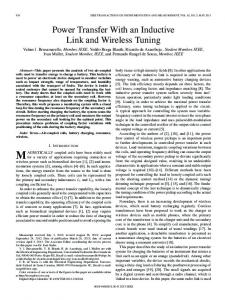
Figure 16: Finalized Prototype of Product
D. Rectifier Circuit The diode that was used in Wheatstone Bridge is UF4004, which is an ultrafast rectifier. This diode was able to convert alternating current (AC) to direct current (DC) at high frequency. Besides, a 33µF capacitor was used for the smoothing purpose. As the result, 10.1V of stable voltage was obtained, as shown in Figure 15.
IV. EXPERIMENTAL ANALYSIS A total of three analysis was carried out, which are the efficiency versus distance, efficiency versus misalignment and efficiency versus position. The efficiency of this project can be computed as: 𝐸𝑓𝑓𝑖𝑐𝑖𝑒𝑛𝑐𝑦, 𝜂 =
𝑂𝑢𝑡𝑝𝑢𝑡 𝑃𝑜𝑤𝑒𝑟 × 100% 𝐼𝑛𝑝𝑢𝑡 𝑃𝑜𝑤𝑒𝑟
(7)
A. Analysis of Efficiency versus Distance Table 2 shows the results for the efficiency of devices with the various lengths of distances. Table 2 Analysis for Multiple Devices at Different Distance
Figure 15: Experimental Result of Rectifier circuit
E. Final Product Implementation for Inductive Power Transfer Figure 16 shows the final product and several analysis carried out to show the effectiveness of the proposed method. The analysis was done based on distance, misalignment and position characteristics. The detailed results are presented in the following part.
Distance (mm)
Voltage (V)
Current (mA)
Condition
Efficiency (%)
0 1 2 3 4 5 6 7 8 9 10
11.27 11.26 11.20 11.16 11.15 11.11 11.10 11.08 11.03 10.97 10.96
64.10 63.16 62.71 60.44 58.78 55.26 53.21 51.31 50.18 46.56 44.51
ON ON ON ON ON ON ON ON ON ON ON
75.25 74.08 73.16 70.26 68.27 63.95 61.52 59.22 57.65 53.20 50.82
ISSN: 2180 – 1843 e-ISSN: 2289-8131 Vol. 8 No. 5 May – August 2016
115
Journal of Telecommunication, Electronic and Computer Engineering Table 4 Analysis for Desk Lamp in Position
Efficiency versus Distance Efficiency (%)
80 60
Position
40
Voltage (V) 11.56 11.62 11.61
1 2 3
20 0 0
1
2
3
4 5 6 7 Distance (mm)
8
9
Efficiency (%) 83.47 84.39 84.08
Table 5 Analysis for Clock in Position
10 11
Figure 17: Graph of Efficiency vs Distance
Desk Lamp Current Condition (mA) 69.32 ON 69.72 ON 69.52 ON
Position
Voltage (V) 11.87 11.78 11.62
1 2 3
This analysis has been conducted by increasing the distance between transmitter and receiver coils. According to this analysis, when the distance is increased, the efficiency of this project is decreased. This is because the strength of magnetic field becomes weaker as the distances farther.
Current (mA) 70.32 70.42 70.39
Clock Condition ON ON ON
Efficiency (%) 86.95 86.41 85.20
Efficiency versus Position 90
Table 3 Analysis for Multiple Devices in Misalignment
88
Efficiency (%)
B. Analysis of Efficiency versus Misalignment Table 3 shows the results of the experiments conducted for misalignment.
86 Desk Lamp Clock
84 82 80
Distance (mm)
Voltage (V)
Current (mA)
Condition
Efficiency (%)
0 1 2 3 4 5 6 7 8 9 10
11.23 11.19 11.13 11.11 11.07 11.05 10.98 10.96 10.91 10.87 10.80
64.12 63.89 62.39 60.63 59.58 57.82 53.20 51.88 48.81 42.46 38.27
ON ON ON ON ON ON ON ON ON ON ON
75.01 74.47 72.33 68.95 68.70 66.55 60.84 59.23 55.50 48.08 43.05
Efficiency Versus Misalignment
Efficiency (%)
80
40 20 0 1
2
3 4 5 6 7 8 Misalignment Distance (mm)
9
10
11
Figure 18: Graph of Efficiency vs Misalignment
The analysis of misalignment was conducted by changing the position of receiver coil vertically. The resulting analysis showed that the efficiency is reduced by misalignment. This is due to the magnetic field at the side transmitter coil is not strong as compared to the center. C. Analysis of Efficiency versus Position Table 4 and 5 show the results of the experiment conducted to prove the efficiency of the multiple devices powered up in different positions. 116
2 Position
3
Figure 19: Graph of Efficiency vs Position
According to Figure 19, the efficiency has a small change when the device was placed in different position. This is because the strength of magnetic field generated by transmitter coil is constant. In this experimental process, position 1 means that the transmitting coil is located at the left of coil shown in Figure 9, meanwhile for position 2, the transmitting coil is at the center. Whereas for position 3, the transmitter is at the right of the coil shown in Figure 9. V. CONCLUSION
60
0
1
In conclusion, the development of Wireless Power Transfer for low-power multiple devices has been successfully done by using Class E inverter as an inverter. The performance of the system has been analyzed in terms of distance, misalignment and position between the transmitter and receiver coil. In terms of distance, the highest achievement of the system was almost 75% with distance in which it was separated by a thin paper and for misalignment part, the best efficiency achieved was 75.01%. Then, for position analysis, there was only a slight difference in the results for any position placed. Finally, wireless power transfer implementation on low-power multiple devices was successful demonstrated using a desk lamp and a digital clock. By doing this work, the number of power outlets and wires usage were reduced which made the workspace neat and tidy. Considering that this research will contribute to wires and risk of accidents reduction, the system can be used for long term since it has very low radiation, which may not affect the surrounding. In the future, the
ISSN: 2180 – 1843 e-ISSN: 2289-8131 Vol. 8 No. 5 May – August 2016
Development of Wireless Power Transfer using Inductive Approach to Power Up Multiple Low Power Devices
project can be improved in term of its efficiency by adding an impedance matching network to ensure higher power multiple devices, such as smartphones and mini fan, which are able to be charged and operated like normal. ACKNOWLEDGMENT We would like to express our gratitude towards Universiti Teknikal Malaysia Melaka (UTeM) for giving us opportunity to accomplish this project under the institution at Faculty of Electronics Engineering and Computer Engineering and Ministry of Higher education Malaysia for funding this work under grant number of RAGS/1/2014/TK03/FKEKK/B00062. REFERENCES [1]
[2]
Su Choon Chung. (2013). New Methods For Capacitive Wireless Power Transfer. Department of Electrical and Electronic Engineering, Faculty of Engineering Science, Universiti Tunku Abdul Rahman. Xiao Lu, Dusit Niyato, Ping wang, Dong In Kim, Zhu Han. (9 Dec 2014). Wireless Charger Networking for Mobile Devices: Fundamentals, Standards, and Applications. arXiv:1410.8635v2 [cs.NI].
[3]
Ajey Kumar. R, Gayathri. H. R, Bette Gowda. R, Yashwanth. B. (May 2014). WiTricity: Wireless Power Transfer By Non-radiative Method. International Journal Engineering Trends and Technology (IJETT) Volume 11 Number 6. [4] Dr. Morries Kesler. (2013). Highly Resonant Power Transfer: Safe, Efficient and Over Distance. WiTricity. [5] Ziff-Davis. (2014, December 15). Encyclopedia of Terms. Retrieved from PC Magazine:http://www.pcmag.com/encyclopedia/term/57396/ wireless-energy-transfer [6] Xia Chen-yang, Li Chao-wei, Zhang Juan. (2011, August 19-22). Analysis of Power transfer Characterisitic of Capacitive Power Transfer System and Inductively Coupled Power Transfer System. Jilin, China. [7] Maurice G.L. Roes, Jorge L. Duarte, Marcel A.M. Hendrix, Elena A. Lomonova. (October 2013). Acoustic Energy Transfer: A Review. IE Tech New [8] M. Kazimierczuk and D. Czarkowski, Resonant power converters. Hoboken, N.J.: Wiley, 2011. [9] T. Kraison, H. Akihiro, N. Yuji and T. Kazuhiro, Design and Evaluation of a Wireless Power Transfer System with Road Embedded Transmitter Coils for Dynamic Charging of Electric Vehicles. Kanagawa, Japan, Nov 2013 [10] Grant A. Covic, Senior IEEE, John T. Boys. (2013). Inductive Power Transfer. Invited Paper, 1. [11] Thoriq Zaid, Shakir Saat, Yusmarnita Yusop, Norezmi Jamal. (2014). Contactless Energy Transfer Using Acoustic Approach - A Review. International Conference on Computer, Communication and Control Technology.
ISSN: 2180 – 1843 e-ISSN: 2289-8131 Vol. 8 No. 5 May – August 2016
117