energies Article
Device Performance Improvement of Double-Pass Wire Mesh Packed Solar Air Heaters under Recycling Operation Conditions Chii-Dong Ho *, Hsuan Chang, Chun-Sheng Lin, Chun-Chieh Chao and Yi-En Tien Energy and Opto-Electronic Materials Research Center, Department of Chemical and Materials Engineering, Tamkang University, Tamsui, New Taipei 251, Taiwan;
[email protected] (H.C.);
[email protected] (C.-S.L.);
[email protected] (C.-C.C.);
[email protected] (Y.-E.T.) * Correspondence:
[email protected]; Tel.: +886-2-2621-5656 (ext. 2724); Fax: +886-2-2620-9887 Academic Editor: Timothy Anderson Received: 18 December 2015; Accepted: 18 January 2016; Published: 22 January 2016
Abstract: The improvement of device performance of a recycling solar air heater featuring a wire mesh packing was investigated experimentally and theoretically. The application of the wire mesh packing and recycle-effect concept to the present study were proposed aiming to strengthen the convective heat-transfer coefficient due to increased turbulence. Comparisons were made among different designs, including the single-pass, flat-plate double-pass and recycling double-pass wire mesh packed operations. The collector efficiency of the recycling double-pass wire mesh packed solar air heater was much higher than that of the other configurations for various recycle ratios and mass flow rates scenarios. The power consumption increment due to implementing wire mesh in solar air heaters was also discussed considering the economic feasibility. A fairly good agreement between theoretical predictions and experimental measurements was achieved with an analyzed error of 1.07%–9.32%. Keywords: wire mesh packing; heat-transfer efficiency; double-pass; recycling; solar air heater
1. Introduction Various solar air heater configurations have been implemented to enhance collector efficiency compared to a simple flat-plate device consisting of glass covers, an absorber plate and air flow channels. Razika et al. [1] and Al-Kayiem and Yassen [2] discussed the effect of the inclination angle on the absorption-convection heat transfer mechanism in a solar air collector. El-Sebaii and Al-Snani [3] investigated the effects of using absorber plates coated with various selective coating materials on the collector performance. Vaziri et al. [4] presented the collector performances of new solar air collector designs having different inner collector colors. Many improved devices were designed taking into account the design parameters for strengthening the convective heat-transfer coefficient [5], enlarging heat-transfer area [6], and increasing flow turbulence [7]. Several investigators have confirmed the technical feasibility of the recycle-effect application to heat transfer devices and reactors. Ho et al. [8,9] derived the theoretical formulations of the recycle-effect concept to heat and mass transfer through a parallel-plate channel with recycle. Fudholi et al. [10] developed the improvement potential of the solar collector based on energy and exergy analyses. Singh and Dhiman [11] proposed an analytical study to predict the thermal and thermohydraulic efficiencies of recycling double-pass packed bed solar air collectors. Garg et al. [12] extended solar air heater operation to multiple-pass operations. Enhancement of convective heat-transfer coefficients was achieved by increasing the intensity of the turbulence in recycling solar air collectors with double-pass [13] and multi-pass [14] operations. In this work a new solar air heater design adopting a wire mesh packed double-pass design under recycling
Energies 2016, 9, 68; doi:10.3390/en9020068
www.mdpi.com/journal/energies
Energies 2016, 9, 68 Energies 2016, 9, 68 Energies 2016, 9, 68
2 of 10 2 of 11 2 of 11
is proposed proposed and studied. studied. There are two purposes in studied. the present present study: first, purposes to obtain obtain in theoretical operation, as shown in Figures 1 and 2 two is proposed and There are two the present is and There are purposes in the study: first, to theoretical predictions and to obtain the experimental results for the recycling double‐pass wire mesh packed predictions and to obtain the experimental results for the recycling double‐pass wire mesh packed study: first, to obtain theoretical predictions and to obtain the experimental results for the recycling solar air heater; and second, to study the effects of the recycle ratio and air mass flow rate on the solar air heater; and second, to study the effects of the recycle ratio and air mass flow rate on the double-pass wire mesh packed solar air heater; and second, to study the effects of the recycle ratio and heat‐transfer efficiency enhancement and to make an economic consideration of both heat‐transfer airheat‐transfer efficiency enhancement and to make an economic consideration of both heat‐transfer mass flow rate on the heat-transfer efficiency enhancement and to make an economic consideration efficiency improvement and power consumption increment. of efficiency improvement and power consumption increment. both heat-transfer efficiency improvement and power consumption increment.
Wire mesh mesh Wire
Glass covers covers Glass
Absorbing Absorbing plate plate
Bottom Insulation Insulation Bottom plate plate
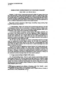
Figure 1. Configuration of a recycling double-pass solar air heater. Figure 1. Configuration of a recycling double‐pass solar air heater. Figure 1. Configuration of a recycling double‐pass solar air heater.
Glass cover cover 22 Glass Glass cover 11 Glass cover b,0 TTb,0
a,i TTa,i
TTPP
H H
Absorbing plate plate Absorbing
a,0 TTa,0
b,L TTb,L
a,L TTa,L
TTRR
= 00 zz =
Bottom plate plate Bottom Insulation zz == LL Insulation
Figure 2. A double-pass solar air heater with internal attached wire mesh. Figure 2. A double‐pass solar air heater with internal attached wire mesh. Figure 2. A double‐pass solar air heater with internal attached wire mesh.
2. Temperature Distributions
.
Before entering the lower subchannel, the inlet air mass flow rate and inlet temperature of m . and Ta,i is premixed with the recycling air flow Rm exits from the lower subchannel with the outlet
Energies 2016, 9, 68
3 of 10
temperature Ta,L . A schematic configuration is depicted in Figure 1 while the air flow arrangement is shown in Figure 2. By following the similar mathematical treatment and experimental studies performed in our previous work [15], except instead for the wire mesh packing, the analytical solutions of the temperature distributions of the flowing air in the lower and upper subchannels can be obtained in dimensionless form as: B3 B4 ´ B1 B6 Ta pξq “ C1 eY1 ξ ` C2 eY2 ξ ` ` Ts (1) B1 B5 ´ B2 B4 Tb pξq “
Y2 ´ B5 B5 pB3 B4 ´ B1 B6 q B6 Y1 ´ B5 C1 eY1 ξ ` C2 eY2 ξ ´ ` Ts ´ B4 B4 B4 pB1 B5 ´ B2 B4 q B4
(2)
For the definitions of Bi , Gi , Mi , Yi , Ci , Fi and Ii readers are referred to the Appendix. The outlet temperature of Tb,0 can be calculated from Equation (2): Tb p0q “ Tb,0 “
Y2 ´ B5 B5 pB3 B4 ´ B1 B6 q B6 Y1 ´ B5 C1 ` C2 ´ ´ ` Ts B4 B4 B4 pB1 B5 ´ B2 B4 q B4
(3)
Estimation of the useful energy gained by the flowing air was obtained from the energy balance on the lower subchannel, upper subchannel and whole solar air heater with the known inlet and outlet temperatures, respectively:
or:
` ˘ . . Qu “ m p1 ` Rq C p pTa,L ´ Ta,0 q ` mC p Tb,0 ´ Tb,L
(4)
` ˘ . ` ˘ ` ˘ . . Qu “ mC p Ta,L ´ Ta,i ` mC p Tb,0 ´ Tb,L “ mC p Tb,0 ´ Ta,i
(5)
For simplicity, the collector efficiency η W of the double-pass wire mesh packed solar air heater with external recycle was obtained from the actual useful energy gained by the airflow and the incident solar radiation as: ηW
“
Qu pUseful gain of energy carried away by airq I0 Ac pTotal solar radiation incidentq ˘ ` . I0 τg2 α p ´ UL pTp,m ´ Ts q mC p Tb,0 ´ Ta,i “ “ I0 Ac I0
(6)
Equating and rearranging the terms of Equation (6), the average absorber temperature was obtained as: .
Tp,m “
Ts ` pI0 τg2 α p {UL q ´
mC p pTb,0 ´ Ta,i q “ Ts ` pI0 {UL qpτg2 α p ´ ηW q Ac UL
(7)
3. Experimental Studies The experimental setup of the recycling double-pass wire mesh packed solar air heater with subchannel width, length and height of 0.3 m, 0.3 m and 0.05 m, respectively, is shown in Figure 3. One set of heat sources with on/off switch consisted of 14 energy supplies (110 V, 125 W) situated 0.15 m above the glass cover, and the insolation was measured and recorded with instantaneous solar radiation meter (Model No. 455, the Epply Laboratory Inc., St. Paul, MN, USA). Temperatures of flowing air in the interior and at the inlet and outlet of the collector and the air mass flow rate were measured while the ambient temperature was regulated using an air conditioner. Before entering . the lower subchannel, the airflow with mass flow rate m and temperature Ta,i will premix the air . flow exiting from the lower subchannel with Rm and Ta,L which is regulated by means of a valve situated at the end of the lower subchannel. Twenty pieces of the wire mesh were welded into the lower subchannel using a mesh interval of 0.015 m and mesh pitch of 0.003 m. The experimental runs
Energies 2016, 9, 68
4 of 11
Energies 2016, 9, 68 4 of 10 R m and Ta,L which is regulated by means of a the air flow exiting from the lower subchannel with
valve situated at the end of the lower subchannel. Twenty pieces of the wire mesh were welded into the lower subchannel using a mesh interval of 0.015 m and mesh pitch of 0.003 m. The experimental were runs were carried out to supply the ambient air by a blower (Teco 3 Phase Induction Motor, Model carried out to supply the ambient air by a blower (Teco 3 Phase Induction Motor, Model BL modelBL model 552, Redmond Co, Owosso, MI, USA) which was measured by an anemometer (Kanmax 552, Redmond Co, Owosso, MI, USA) which was measured by an anemometer (Kanmax Japan Inc., Osaka, Japan). By substituting the specified values into values the appropriate equations, equations, the theoretical Japan Inc., Osaka, Japan). By substituting the specified into the appropriate predictions were obtained and were also presented graphically in Figures 4 and 5in forFigures comparisons the theoretical predictions obtained and also presented graphically 4 and 5 between for comparisons between different devices. different devices. F
B
D
c E
J
A
K
G Air Out
I
H
c D
Air In
(A) Air heater (B) Artificial simulation (C) Blower (D) Transformer (E) Air mixer (F) Air conditioner (G) Temperature indicator (H) Fan (I) Air box (J) Valve (K) Pyranometer
Figure 3. Schematic diagram of a double-pass solar air heater with artificial simulation. Figure 3. Schematic diagram of a double‐pass solar air heater with artificial simulation.
4. Results and Discussion 4. Results and Discussion Moffat [16] determined the precision analysis of each individual measurement directly from the Moffat [16] determined the precision analysis of each individual measurement directly from the experimental run as follows: experimental run as follows: 2 N $ ´ exp,i exp,i ¯ 2 , 1{2 S ’ N / exp &ÿ i 1 ηexp,iN´ 1η exp,i . Sηexp “ ’ / N´1 % i “1 and the mean value of resulting uncertainty of experimental runs was defined by: 12
exp
exp
(8)
(8)
Sexp runs was defined by: and the mean value of resulting uncertainty of experimental Sexp (9) N exp Sηexp Sη exp “ a 0 = 1100 W/m2 with three air mass flow rates (9) Estimations of the precision index for I 0 = 830 and I Nexp were calculated. The mean precision index of the experimental measurements in Figures 4 and 5 ranged between 2.80 10 3 S exp 7 .75 10 3 . Meanwhile, deviations between the experimental 2
Estimations of the precision index for I0 = 830 and I0 = 1100 W/m with three air mass flow rates results the theoretical predictions may be defined as: were calculated. The mean precision index of the experimental measurements in Figures 4 and 5 N ´ 3 . Meanwhile, deviations between the experimental ranged between 2.80 ˆ 10´3 ď Sη exp ď 7.75 1ˆ 10 theo,i exp,i defined 100% (10) as: results the theoretical predictions mayEbe N exp theo,i exp
i 1
ˇ Nexp ˇ where Nexp, ηtheo,i and ηexp,i are the number of experimental measurements, theoretical predicted and 1 ÿ ˇηtheo,i ´ ηexp,i ˇ experimental data of collector respectively. Accuracy deviations were calculated and (10) E efficiencies, “ ˆ 100% Nexp ηtheo,i shown in Table 1 within 1.33 ≤ E ≤ 9.32 under two incident solar radiations I 0 for two configurations i“1 without (flat‐plate type) and with attached wire mesh. It is seen that the experimental results fairly whereconfirm the theoretical predictions, as indicated from Table 1. Comparisons between the theoretical Nexp , η theo,i and η exp,i are the number of experimental measurements, theoretical predicted and experimental data experimental of collector efficiencies, respectively. deviations calculated predications and results were achieved in Accuracy good agreement, as were observed from and shown in Table 1 within 1.33 ď E ď 9.32 under two incident solar radiations I0 for two configurations Figures 4 and 5. without (flat-plate type) and with attached wire mesh. It is seen that the experimental results fairly confirm the theoretical predictions, as indicated from Table 1. Comparisons between the theoretical predications and experimental results were achieved in good agreement, as observed from Figures 4 and 5.
Energies 2016, 9, 68
5 of 10
Energies 2016, 9, 68
5 of 11
Energies 2016, 9, 68
5 of 11
Table 1. Deviations between the experimental results and theoretical predictions. Table 1. Deviations between the experimental results and theoretical predictions. Table 1. Deviations between the experimental results and theoretical predictions. Nˇexp ˇ theo ,i exp, ˇ i exp ˇη 1 1Nř theo,i ´ ηexp,i 100 % E N exp ˆ 100% E“ N1exp theo , i exp, i Nexp η theo,itheo ,i i“1 i 1
E Flat-PlateNType Flat‐Plate Type exp i 1
m (kg/h) m. (kg/h) m 38.52 (kg/h) 38.52 57.96 38.52 57.96 77.04 77.04 57.96
2) 2 I0I (W/m Flat‐Plate Type 0 (W/m ) 2 830 830 1100 I0 (W/m ) 1100 7.17 9.32 830 1100 7.17 9.32 4.70 2.82 7.17 9.32 4.70 2.82 3.25 1.33 3.25 1.33 4.70 2.82
77.04
3.25 0.80 0.80 0.75
100 %
Wire Packed Wire Mesh Packed theo , i Mesh ) I0 Wire Mesh Packed (W/mI20 (W/m ) 2
830 I1100 0 (W/m ) 1100 1.65 1.07 830 1100 1.65 1.07 7.44 6.87 1.07 7.44 1.65 6.87 7.08 5.54 7.08 7.44 5.54 6.87 2
830
1.33
7.08
5.54
I0=830 W/m2 I0=830 W/m2
0.75 0.70 0.70 0.65
D andand D W W
0.65 0.60 0.60 0.55 0.55 0.50 0.50 0.45 0.45 0.40 0.40 0.35 0.35 0.30 0.30 0.25 0.0 0.25 0.0
flat-plate flat-plate flat-plate flat-plate wire mesh flat-plate wire mesh flat-plate wire mesh mesh wire wire mesh wire mesh 0.5
0.5
Theo.
Exp.
Theo.
Exp.
1.0
1.5
m (kg/h) 38.52 m57.96 (kg/h) 77.04 38.52 38.52 57.96 57.96 77.04 77.04 38.52 57.96 77.04 2.0
1.0R
1.5
2.0
R Figure 4. Effects of recycle ratio and air mass flow rate on collector efficiencies (I 0 = 830 W/m2). 2
Figure 4. Effects of recycle ratio and air mass flow rate on collector efficiencies (I0 = 830 W/m ). Figure 4. Effects of recycle ratio and air mass flow rate on collector efficiencies (I 0 = 830 W/m2). 0.80 I0=1100 W/m2 0.80 0.75
I0=1100 W/m2
0.75 0.70 0.70 0.65
D andand D W W
0.65 0.60 0.60 0.55 0.55 0.50 0.50 0.45 0.45 0.40 0.40 0.35 0.35 0.30 0.30 0.25 0.0 0.25 0.0
flat-plate flat-plate flat-plate flat-plate wire mesh flat-plate wire mesh flat-plate wire mesh mesh wire wire mesh 0.5 wire mesh
0.5
Theo.
Exp.
Theo.
Exp.
1.0
1.5
1.0 R
1.5
m (kg/h) 38.52 m57.96 (kg/h) 77.04 38.52 38.52 57.96 57.96 77.04 77.04 38.52 57.96 77.04 2.0
2.0
R Figure 5. Effects of recycle ratio and air mass flow rate on collector efficiencies (I 0 = 1100 W/m2). Figure 5. Effects of recycle ratio and air mass flow rate on collector efficiencies (I ). 2 Figure 5. Effects of recycle ratio and air mass flow rate on collector efficiencies (I0 = 1100 W/m 0 = 1100 W/m ). 2
Energies 2016, 9, 68
6 of 10
Effects of recycle ratio and air mass flow rate on collector efficiencies, η D and η W , for both flat-plate type and wire mesh packed devices, respectively, are presented in Figures 4 and 5. Both collector efficiencies, η D and η W , increase with increasing recycle ratios and air mass flow rates owing to the air velocity enlargement, and thus, a higher convective heat transfer coefficient is achieved. Collector performance improvements of ID and IW , for the flat-plate and wire mesh packed double-pass devices, respectively, under the same operating conditions with various incident solar radiations, air mass flow rates and recycle ratios as parameters are defined by the percentage increase in the collector efficiency compared to that in the downward single-pass device as follows: ID “
η D ´ ηS ˆ 100% ηS
(11)
IW “
ηW ´ ηS ˆ 100% ηS
(12)
Some calculated results are presented in Table 2. Table 2. Theoretical predictions of heat-transfer efficiency improvement of ID and IW . I0 = 830 (W/m2 ) m (kg/h)
R
I0 = 1100 (W/m2 )
Flat-Plate
Wire Mesh
Flat-Plate
Wire Mesh
ID (%)
IW (%)
ID (%)
IW (%)
38.52
0.25 0.5 0.75 1 1.25 1.5 1.75 2
38.19 45.63 51.78 56.96 61.49 65.37 68.93 72.17
62.46 76.38 87.06 95.15 101.94 107.12 111.97 115.86
39.16 46.60 52.75 57.93 62.46 66.34 69.90 72.82
63.11 77.67 89.00 98.06 105.18 110.68 115.53 119.42
57.96
0.25 0.5 0.75 1 1.25 1.5 1.75 2
29.73 35.68 40.81 44.86 48.38 51.35 54.05 56.22
62.43 71.62 78.65 83.78 88.38 90.81 94.05 96.22
31.08 37.03 41.89 45.95 49.46 52.43 55.14 57.30
64.59 74.59 81.89 87.57 91.89 95.41 98.11 100.27
77.04
0.25 0.5 0.75 1 1.25 1.5 1.75 2
23.74 28.78 32.85 36.45 39.09 41.73 43.88 45.56
59.95 66.67 71.46 75.06 77.94 79.86 81.53 82.97
24.94 29.98 34.05 37.41 40.29 42.69 44.60 46.52
61.87 69.31 74.34 78.18 81.29 83.45 85.13 86.57
The collector efficiency improvements increase with increasing recycle ratio but to a more remarkable extent with decreasing air mass flow rate. However, there is no significant influence of the incident solar radiation on the collector efficiency improvement. It is seen from Table 2 that the heat-transfer efficiency improvement of the wire mesh packed solar air heater is higher than that of the flat-plate type without attaching the wire mesh. The present work is actually the extension of the previous work [17] except for the different type of the external recycle. The graphical representation for comparisons with some experimental results and theoretical predictions obtained in [17] under the same design and operating parameters were illustrated to explain how the present device is preferred to be employed, as confirmed by Figure 6. This is the value and originality of the present device.
Energies 2016, 9, 68
7 of 11
Energies 2016, 9, 68 7 of 11 same design and operating parameters were illustrated to explain how the present device is preferred Energies 2016, 9, 68 7 of 10 to be employed, as confirmed by Figure 6. This is the value and originality of the present device. same design and operating parameters were illustrated to explain how the present device is preferred 0.85 to be employed, as confirmed by Figure 6. This is the value and originality of the present device. Theo. Exp. (A) R=0.5 (A) R=1.25 Theo. Exp. (B) R=0.5 (A) R=0.5 (B) R=1.25 (A) R=1.25 (B) R=0.5 (B) R=1.25
0.800.85 0.750.80 0.700.75
0.60
W
W
0.65
0.55 0.50 0.45
0.70 0.65 0.60 0.55 0.50
0.40 0.45 40 45 50 55 60 65 70 75 80 85 35
(kg/h) m 0.40 35 40 45 50 55 60 65 70 75 80 85
2). Figure 6. Comparisons of collector efficiency between the present device and the previous work (I 0 = 830 W/m Figure 6. Comparisons of collector efficiency between the present device and the previous work (kg/h) m (I0 = 830 W/m2 ).
The power consumption increment for the wire mesh packed devices IP (PS and PW single‐pass Figure 6. Comparisons of collector efficiency between the present device and the previous work (I 0 = 830 W/m2). and double‐pass devices, respectively) is defined by the percentage increase in the power The power consumption increment for the wire mesh packed devices IP (PS and PW single-pass consumption compared to that in the downward single‐pass device [18,19]: The power consumption increment for the wire mesh packed devices I (PS and P single‐pass and double-pass devices, respectively) is defined by the percentage increase inPthe powerWconsumption and double‐pass is defined by the percentage increase in the power P respectively) PS single-pass compared to that in devices, the downward device [18,19]: for wire mesh packed solar air heaters IP W (13) consumption compared to that in the downward single‐pass device [18,19]: PS PW ´ PS IP “ P wire mesh packed solar air heaters (13) W PS for for wire mesh packed solar air heaters The ratio IW/IP of both efficiency improvement IW and the power consumption I Pthe collector PS (13) PS account both effect indexes for economic considerations in increment IP is illustrated to take into The ratio I /I of both the collector efficiency improvement IW and the power consumption W P obtaining the suitable selections of the operating parameters. The results indicate the optimal ratio of The ratio IW/IP of both the collector efficiency improvement IW and the power consumption increment illustrated tovarious take into account both effect indexesin for economic considerations in P is IW /I P occurs Iat 0.5~1.0 for mass flow rates, as indicated Figure 7. It is of practical in increment IP R is = illustrated to take into account both effect indexes for economic considerations obtaining the suitable selections of the operating parameters. The results indicate the optimal ratio importance that applications of recycling operation and wire mesh packing for enhancing device obtaining the suitable selections of the operating parameters. The results indicate the optimal ratio of of IW /IP occurs at R = 0.5~1.0 for various mass flow rates, as indicated in Figure 7. It is of practical performance of wire mesh packed solar air heaters is technically and economically feasible. IW/IP occurs at R = 0.5~1.0 for various mass flow rates, as indicated in Figure 7. It is of practical importance that applications of0.80 recycling operation and wire mesh packing for enhancing device 2 importance that applications of recycling I0=830W/moperation and wire mesh packing for enhancing device performance of wire mesh packed solar air heatersm is technically and economically feasible. =38.52(kg/h) performance of wire mesh packed solar air heaters is technically and economically feasible. 0.80 0.75
I0=830W/m
2
=38.52(kg/h) m =57.69(kg/h) m =57.69(kg/h) m
0.70
IW / IP
IW / IP
0.75
0.70
=77.04(kg/h) m
0.65
=77.04(kg/h) m
0.65 0.60 0.0
0.5
1.0
1.5
R
2.0
0.60 Figure 7. Effects of recycle ratio and air mass flow rate on the value of I W/IP. 0.0 0.5 1.0 1.5 2.0 R
Figure 7. Effects of recycle ratio and air mass flow rate on the value of IWW/I /IPP. . Figure 7. Effects of recycle ratio and air mass flow rate on the value of I
Energies 2016, 9, 68
8 of 10
5. Conclusions The collector efficiency improvement in recycling double-pass solar air heaters with wire mesh packing have been developed analytically and experimentally. The comparisons of double-pass configurations with and without attaching a wire mesh were made to investigate the device performance improvement. The new design in the present study provides better collector efficiency due to the convective heat-transfer coefficient enhancement which the turbulent intensity created with the wire mesh attachment. The forgoing results can be summarized as follows: (1) With recycling operations and inserting a wire mesh, the collector efficiency increases with increasing recycle ratio R, incident solar radiation and air mass flow rates; (2) Collector performance improvements increase with increasing recycle ratio but with decreasing air mass flow rate, and no significant influence is found with respect to the incident solar radiation; (3) The optimal operating conditions for economic considerations of collector efficiency improvements with a relative small compensation of hydraulic dissipated energy increment were found at R = 0.5~1.0 for various mass flow rates; (4) the advantages of the present device are evident, and they will be an important contribution to the design of any particular application coupling external recycle and packing materials. Acknowledgments: The authors wish to thank the Ministry of Science and Technology of the Republic of China for the financial support. Author Contributions: This paper is a result of the full collaboration of all the authors. However, the concept for this research was conceived by Chii-Dong Ho, Chun-Sheng Lin contributed to mathematical derivations, Hsuan Chang and Yi-En Tien elaborated the manuscript preparation and Chun-Chieh Chao performed the experiments. Conflicts of Interest: The authors declare no conflict of interest.
Nomenclature Ac = surface area of the collector = LW (m2 ) C p = specific heat of air at constant pressure (J/(kg¨ K)) E = deviation of the experimental measurements from theoretical predictions, defined in Equation (8) h a = convection coefficient between the bottom and lower subchannel (W/m2 ¨ K) hb = convection coefficient between the absorber plate and upper subchannel (W/m2 ¨ K) hr,p´c1 = radiation heat transfer coefficient between cover 1 and absorber plate (W/m2 ¨ K) hr,p´R = radiation heat transfer coefficient between absorber plate and bottom plate (W/m2 ¨ K) H = height of both upper and lower channels (m) I0 = incident solar radiation (W/m2 ) ID = percentage of collector efficiency improvement in flat-plate air heater, defined in Equation (11) IW = collector efficiency improvement index, defined in Equation (12) IP = power consumption increment, defined in Equation (13) L = channel length (m) . m = total air mass flow rate (kg/h) Nexp = number of experimental measurements PD = power consumption of the double-pass air heater (W) PS = power consumption of downward-type single-pass device (W) Qu = useful energy gained by air (W) R = recycle ratio Sηexp = the precision index of an individual measurement Sη exp = the mean value of Sηexp Ta,i = inlet air temperature (K) Ta,0 = the mixing temperature of the subchannel a at x = 0 (K) Ta,L = the temperature of the subchannel a at x = L (K)
Energies 2016, 9, 68
9 of 10
Tb,0 = the temperature of the subchannel b at x = 0 (K) Tb,L = the temperature of the subchannel b at x = L (K) Ta = axial fluid temperature distribution in the lower subchannel (K) Tb = axial fluid temperature distribution in the upper subchannel (K) UB = loss coefficient from the bottom of solar air heater to the ambient environment (W/m2 ¨ K) UB´s = loss coefficient from the surfaces of edges and the bottom of the solar collector to the ambient environment (W/m2 ¨ K) Uc1´s = loss coefficient from the inner cover to the ambient environment (W/m2 ¨ K) UT = loss coefficient from the top of solar air heater to the ambient environment (W/m2 ¨ K) W = width of both upper and lower subchannels (m) z = axial coordinate (m) Greek Letters ηD = collector efficiency of the flat-plate double-pass device ηS = collector efficiency of the downward type single-pass device ηW = collector efficiency of the wire mesh packed solar air heater ηexp,i = experimental data of collector efficiency η exp,i = the mean value of the experimental data ηexp,i ηtheo,i = theoretical prediction of collector efficiency ξ = dimensionless channel length Appendix ` ˘ . B1 “ ´W hb G1 ` hb hr,p´c1 G1 G4 ´ Uc1 ´s hb G4 {RmC p ` ˘ . B2 “ ´W hb G2 ` hb hr,p´c1 G2 G4 {RmC p ` ˘ . B3 “ ´W hb G3 ` hb hr,p´c1 G3 G4 {RmC p ` ˘ . B4 “ W h a G6 ` h a hr,p´R G6 G7 { p1 ` Rq mC p ` ˘ . B5 “ W h a G5 ` h a hr,p´R G5 G7 ´ UB´s h a G7 { p1 ` Rq mC p ` ˘ . B6 “ W h a G3 ` h a hr,p´R G3 G7 { p1 ` Rq mC p
(A1) (A2) (A3) (A4) (A5) (A6)
G1 “ ´ph a ` UT ` UB q{pUT ` UB ` h a ` hb q
(A7)
G2 “ h a {pUT ` UB ` h a ` hb q
(A8)
G3 “ I0 a p τg2 {pUT ` UB ` h a ` hb q
(A9)
G4 “ phr,p´c1 ` hb ` Uc1 ´s q´1
(A10)
G5 “ ´phb ` UT ` UB q{pUT ` UB ` h a ` hb q
(A11)
G6 “ hb {pUT ` UB ` h a ` hb q
(A12)
G7 “ phr,p´R ` h a ` UB´s q´1 b pB1 ` B5 q ` pB1 ´ B5 q2 ` 4B2 B4
(A13)
Y1 “
Y2 “ 1 C1 “ F1
«
(A14)
2 pB1 ` B5 q ´
b pB1 ´ B5 q2 ` 4B2 B4
(A15)
2 F2 I2 eY2 ´ B4 pF2 ´ F3 qp1 ` R ´ ReY2 q
I2 eY2 p1 ` R ´ ReY1 q ´ I1 eY1 p1 ` R ´ ReY2 q
ff (A16)
Energies 2016, 9, 68
10 of 10
1 C2 “ ´ F1
«
F2 I1 eY1 ´ B4 pF2 ´ F3 qp1 ` R ´ ReY1 q I2 eY2 p1 ` R ´ ReY1 q ´ I1 eY1 p1 ` R ´ ReY2 q
ff (A17)
F1 “ B1 B5 ´ B2 B4
(A18)
F2 “ B3 B4 ´ B1 B6
(A19)
F3 “ B2 B6 ´ B3 B5
(A20)
I1 “ Y1 ´ B4 ´ B5
(A21)
I2 “ Y2 ´ B4 ´ B5
(A22)
References 1. 2. 3. 4. 5. 6. 7. 8. 9. 10.
11. 12. 13. 14. 15. 16. 17. 18. 19.
Razika, I.; Nabila, I.; Madani, B.; Zohra, H.F. The effects of volumetric flow rate and inclination angle on the performance of a solar thermal collector. Energy Convers. Manag. 2014, 78, 931–937. [CrossRef] Al-Kayiem, H.H.; Yassen, T.A. On the natural convection heat transfer in a rectangular passage solar air heater. Sol. Energy 2015, 112, 310–318. [CrossRef] El-Sebaii, A.A.; Al-Snani, H. Effect of selective coating on thermal performance of flat plate solar air heaters. Energy 2010, 35, 1820–1828. [CrossRef] Vaziri, R.; Ilkan, M.; Egelioglu, F. Experimental performance of performance of perforated glazed solar air heaters and unglazed transpired solar air heater. Sol. Energy 2015, 119, 251–260. [CrossRef] Kreith, F.; Kreider, J.F. Principles of Solar Engineering; McGraw-Hill: New York, NY, USA, 1978. Duffie, J.A.; Beckman, W.A. Solar Engineering of Thermal Processes, 3rd ed.; Wiley: New York, NY, USA, 1980. Gao, W.; Lin, W.; Liu, T.; Xia, C. Analytical and experimental studies on the thermal performance of cross-corrugated and flat-plate solar air heaters. Appl. Energy 2007, 84, 425–441. [CrossRef] Ho, C.D.; Yeh, H.M.; Sheu, W.S. An analytical study of heat and mass transfer through a parallel-plate channel with recycle. Int. J. Heat Mass Transfer 1998, 41, 2589–2599. [CrossRef] Ho, C.D.; Yang, W.Y. An analytical study of heat-transfer efficiency in laminar counterflow concentric circular tubes with external refluxes. Chem. Eng. Sci. 2003, 58, 1235–1250. [CrossRef] Fudholi, A.; Sopian, K.; Ruslan, M.H.; Othman, M.Y.; Ruslan, M.H.; Bakhtyar, B. Energy analysis and improvement potential of finned double-pass solar collector. Energy Convers. Manag. 2013, 75, 234–240. [CrossRef] Singh, S.; Dhiman, P. Recyclic double pass packed bed solar air heaters. Int. J. Thermal Sci. 2015, 87, 215–227. Garg, H.P.; Sharma, V.K.; Bhargava, A.K. Theory of multiple-pass solar air heaters. Energy 1985, 10, 589–599. [CrossRef] Wijeysundera, N.E.; Ah, L.L.; Tjioe, L.E. Thermal performance study of two-pass solar air heaters. Sol. Energy 1982, 28, 363–370. [CrossRef] Ho, C.D.; Yeh, C.W.; Hsieh, S.M. Improvement in device performance of multi-pass flat-plate solar air heaters with external recycle. Renew. Energy 2005, 30, 1601–1621. [CrossRef] Ho, C.D.; Yeh, H.M.; Wang, R.C. Heat-transfer enhancement in double-pass flat-plate solar air heaters with recycle. Energy 2005, 30, 2796–2817. [CrossRef] Moffat, R.J. Describing the uncertainties in experimental results. Exp. Therm. Fluid Sci. 1988, 1, 3–17. [CrossRef] Ho, C.D.; Lin, C.S.; Chuang, Y.C.; Chao, C.C. Performance improvement of wire mesh packed double-pass solar air heaters with external recycle. Renew. Energy 2013, 57, 479–489. [CrossRef] Prasad, S.B.; Saini, J.S.; Singh, K.M. Investigation of heat transfer and friction characteristics of packed bed solar air heater using wire mesh as packing material. Sol. Energy 2009, 83, 773–783. [CrossRef] Bird, R.B.; Stewart, W.E.; Lightfoot, E.N. Transport Phenomena, 2nd ed.; Wiley: New York, NY, USA, 2007. © 2016 by the authors; licensee MDPI, Basel, Switzerland. This article is an open access article distributed under the terms and conditions of the Creative Commons by Attribution (CC-BY) license (http://creativecommons.org/licenses/by/4.0/).