Feb 27, 2014 - Parpia, Evanston, IL (US); Mark J. Fisher, Highland Park, IL (US). Quidel Corporation, San Diego, CA. (US); Northwestern University,. Evanston ...
US 20140057271A1
(19) United States (12) Patent Application Publication (10) Pub. No.: US 2014/0057271 A1 (43) Pub. Date:
Kelso et al. (54)
DEVICE WITH CONTROLLED FLUID DYNAMICS, FOR ISOLATION OF AN ANALYTE FROMA SAMPLE
Related US. Application Data
(60) Provisional application No. 61/692,657, ?led on Aug. 23, 2012.
(71) Applicants: Quidel Corporation, San Diego, CA (US); Northwestern University, Evanston, IL (US)
Publication Classi?cation
(51)
Int. Cl.
(52)
U.S. Cl.
C12N15/10
(72)
Inventors: David M. Kelso, Wilmette, IL (US);
Kunal Sur, Evanston, IL (US); Tom Westberg, Gurnee, IL (US); Zaheer Parpia, Evanston, IL (US); Mark J.
Fisher, Highland Park, IL (US)
(73) Assignees: Quidel Corporation, San Diego, CA (US); Northwestern University, Evanston, IL (US)
(21) Appl. No.: 13/972,788 (22)
Filed:
Aug. 21, 2013
Feb. 27, 2014
(2006.01)
CPC ................................ .. C12N15/1006 (2013.01)
USPC ......................... .. 435/6.12; 422/502; 436/177
(57)
ABSTRACT
Devices for use in extracting an analyte of interest from a sample are described. In one embodiment, a device is com prised of a ?rst plurality of chambers, Where one or more chambers in the plurality of chambers has a deep end and a
shallow end With a depth d1. A channel disposed between at least tWo adjacent chambers in the plurality of chambers has a depth greater than d1. The dimensions of the chamber and channel provide control of ?uid movement in the device, particularly When introducing ?uid into the device for its use and during use of the device.
Patent Application Publication
Feb. 27, 2014 Sheet 1 0f 10
US 2014/0057271 A1
Patent Application Publication
Feb. 27 2 14
heet 2 0f 1
Patent Application Publication
Feb. 27, 2014 Sheet 4 0f 10
US 2014/0057271 A1
Patent Application Publication
Feb. 27, 2014 Sheet 5 0f 10
US 2014/0057271 A1
Patent Application Publication
Feb. 27, 2014 Sheet 6 0f 10
US 2014/0057271 A1
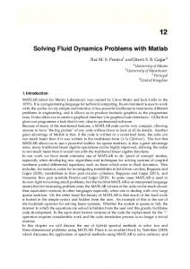
7Fig.
Patent Application Publication
Feb. 27, 2014 Sheet 7 0f 10
US 2014/0057271 A1
180
f
182
192
184
186 190
8Fig.
Patent Application Publication
O O N
Feb. 27, 2014 Sheet 8 0f 10
US 2014/0057271 Al
O
\1
*-
g
N
(\l
= l; 3 . .. D
g
"D
N
d) " D
.21
LL
(0 .. .D
N
11D 00 O (\l
J
Patent Application Publication
Feb. 27, 2014 Sheet 9 0f 10
Fig. 10A 246
248
Fig. 108
US 2014/0057271 A1
Patent Application Publication
Feb. 27, 2014 Sheet 10 0f 10
220
Fig. 10C
US 2014/0057271 A1
Feb. 27, 2014
US 2014/0057271Al
DEVICE WITH CONTROLLED FLUID DYNAMICS, FOR ISOLATION OF AN ANALYTE FROMA SAMPLE CROSS-REFERENCE TO RELATED APPLICATIONS
[0001]
This application claims the bene?t of US. Provi
sional Application No. 61/692,657, ?led Aug. 23, 2012, incorporated herein by reference in its entirety. TECHNICAL FIELD
[0002]
The subject matter described herein relates to a
device for use in sample treatment and analysis applications, Where the device is designed for control of ?uid dynamics Within the chambers and channels of the device. BACKGROUND
[0003] Analysis of biological entities, such as proteins and
nucleic acids, in biological samples generally requires that the target entity in question ?rst be isolated from the biologi cal matrix, Which frequently includes a complex mixture of
end With a depth d1, and Wherein the channel is disposed betWeen tWo chambers having the shalloW end With a depth
d1. [0011] In still another embodiment, each chamber in the plurality of chambers has a volume, Wherein the volume of one chamber in the plurality of chambers differs from the volume of another chamber in the plurality. [0012]
In another embodiment, the one or more chambers
in the plurality of chambers With a deep end and a shalloW end With a depth dl has a ?oor and a side Wall that meet to de?ne four comers, and Wherein at least the comers in the deep end of the chamber are rounded. [0013] In another embodiment, the one or more chambers
in the plurality of chambers With a deep end and a shalloW end With a depth dl has a ?oor and a side Wall that meet to de?ne four comers, and Wherein at least the corners in the shalloW end of the chamber are angled.
[0014]
In yet another embodiment, the device further com
prises a cover having an access port in ?uid communication With a chamber in the plurality of chambers. In one embodi ment, the access port is in ?uid communication With the one
non-target substances. The effective isolation of analytes is a
or more chambers in the plurality of chambers having a deep end and a shalloW end With a depth d1, and Wherein the access
prerequisite for e?icient doWnstream analysis of the analyte, including, for example, ampli?cation of a nucleic acid for
port is positioned for introduction of ?uid directly into the deep end of the chamber.
detection and quanti?cation or identi?cation of a protein or enZyme. It is also important, in many cases, such as in nucleic
[0015] In another embodiment, the device comprises a sec ond plurality of chambers. One or more chambers in the second plurality of chambers has a deep end and a shalloW
acid ampli?cation, that the isolated species not contain resi dues of certain reagents and/ or solvents used during isolation.
[0004] Existing methods of isolation frequently involve multistep processes, often requiring multiple extraction and/ or centrifugation steps, Which require trained personnel and can introduce risks of contamination and/or loss of sample. A need exists for a self-contained device that is effective to isolate an analyte from a biological sample, such as obtained
from a patient, With minimal operator manipulation of sample and reagents. BRIEF SUMMARY
[0005]
end With a depth d1, and a channel disposed betWeen at least tWo adjacent chambers in the second plurality of chambers, the channel having a depth greater than d1. [0016] In one embodiment, the ?rst and second plurality of chambers are linearly parallel. [0017] In another aspect, a method for extracting an analyte of interest from a sample is provided. The method comprises providing a device as described herein, introducing a sample into a ?rst chamber of the device, the ?rst chamber or the sample upon its introduction comprising a solid carrier mem
ber capable interacting With an analyte of interest in the
The folloWing aspects and embodiments thereof
sample, thus forming a carrier-analyte complex; and moving
described and illustrated beloW are meant to be exemplary
the carrier-analyte complex from the ?rst chamber into a second chamber, Wherein said moving transverses the chan
and illustrative, not limiting in scope. [0006] In one aspect, a device as described herein is pro vided. In another aspect, methods of using a device as described herein for isolation or extraction of a target analyte
from a sample is provided. [0007] In another aspect, a device comprising a ?rst plural ity of chambers is provided, Where one or more chambers in the plurality of chambers has a deep end and a shalloW end With a depth d1. A channel is disposed betWeen at least tWo
adjacent chambers in the plurality of chambers, the channel having a depth greater than d1.
nel ?lled With a ?uid.
[0018]
In one embodiment, the channel is ?lled With a gas
or a liquid.
[0019]
In another embodiment, the channel is ?lled With air
or With a Water-immiscible liquid.
[0020]
In still another embodiment, the method further
comprises dispensing a liquid into one or more chambers in
the plurality of chambers. [0021] In yet another embodiment, dispensing a liquid
[0008] In one embodiment, the chambers in the plurality of chambers are serially positioned and each chamber is the
comprises dispensing a lysis solution, a Wash solution, or an elution solution.
plurality is separated by a channel. [0009] In another embodiment, the ?rst plurality of cham
[0022] In one embodiment, the method comprises dispens ing a liquid into the ?rst chamber of the device prior to
introducing a sample. [0023] In another embodiment, the method comprises dis
bers is comprised of at least three chambers, Wherein tWo chambers in the plurality have a deep end and a shalloW end With a depth d1, and Wherein the channel is disposed betWeen the tWo chambers having the shalloW end With a depth d1.
pensing a Water-immiscible substance into the channel.
[0010]
In yet another embodiment, the ?rst plurality of
carrier-analyte complex from a ?rst chamber to a second
chambers is comprised of at least ?ve chambers, Wherein three chambers in the plurality have a deep end and a shalloW
chamber, the Water immiscible liquid in the channel remains
[0024]
In still another embodiment, during moving of the
stationary.
Feb. 27, 2014
US 2014/0057271Al
[0025] In addition to the exemplary aspects and embodi ments described above, further aspects and embodiments will
become apparent by reference to the drawings and by study of
clearly dictates otherwise. Thus, for example, reference to an “excipient” includes a single excipient as well as two or more of the same or different excipients, and the like.
the following descriptions.
[0040]
[0026] Additional embodiments of the present devices and methods will be apparent from the following description, drawings, examples, and claims. As can be appreciated from the foregoing and following description, each and every fea
sample” can include a tissue sample or a body ?uid sample,
ture described herein, and each and every combination of two or more of such features, is included within the scope of the
As pertains to the present disclosure, a “biological
which includes liquid, solid, and semisolid samples, e.g. blood, blood components such as plasma or serum, urine, saliva, sputum, mucous, amniotic ?uid, semen, vaginal secre
tions, tears, spinal ?uid, washings, feces, biopsy specimens, skin, nails, and hair.
present disclosure provided that the features included in such
[0041]
a combination are not mutually inconsistent. In addition, any feature or combination of features may be speci?cally
from other constituents with which it is associated in a sample, such that it can be detected with a desired degree of
excluded from any embodiment of the present invention.
accuracy and precision. The isolated analyte is typically dis
Additional aspects and advantages of the present invention are set forth in the following description and claims, particu larly when considered in conjunction with the accompanying
examples and drawings. BRIEF DESCRIPTION OF THE DRAWINGS [0027]
FIG. 1 is a device or cartridge in accord with one
embodiment; [0028] FIG. 2 shows a perspective view of a cross-section taken through one of the chambers in a device; [0029]
FIG. 3 is a cross-sectional view of a chamber in a
device; [0030] FIG. 4 is a cross-sectional view taken along the longer axis of a device through the gap between adjacent
chambers; [0031]
FIG. 7 shows a device in accord with another
FIG. 8 shows a device in accord with another
embodiment; FIG. 9 shows yet another device in accord with other
embodiments; and [0036] FIGS. 10A-10C illustrate another device according to still other embodiments. DETAILED DESCRIPTION
I. De?nitions
[0037] Various aspects now will be described more fully hereinafter. Such aspects may, however, be embodied in many different forms and should not be construed as limited to the
embodiments set forth herein; rather, these embodiments are provided so that this disclosure will be thorough and com plete, and will fully convey its scope to those skilled in the art. [0038] Where a range of values is provided, it is intended that each intervening value between the upper and lower limit of that range and any other stated or intervening value in that stated range is encompassed within the disclosure. For example, if a range of l [rm to 8 um is stated, it is intended that 2 pm, 3 pm, 4 pm, 5 pm, 6 pm, and 7 pm are also explicitly disclosed, as well as the range of values greater than or equal to l um and the range of values less than or equal to 8 pm.
[0039]
and water-immiscible liquids. [0043] A “reagent solution” typically refers to an aqueous solution. The “reagent” may be a chemical or biological sub stance that causes a chemical change to a sample component, or it may be simply a buffering agent, a salt, or a solvent. II. Device
suspected of containing the analyte. In one embodiment, the sample is a biological sample. In other embodiments, the
embodiment, for use in high throughput and multiplexing
[0035]
to any liquid contained within any of the chambers of the device as described herein, including aqueous, nonaqueous,
FIG. 6 shows a device in accord with another
applications; [0034]
be present in the sample. [0042] A “liquid reagent”, as the term is used herein, refers
[0044] Disclosed herein, in one aspect, is a device for extraction of an analyte of interest from a sample or matrix
embodiment, where dispensing pipettes are shown interact ing with some chambers in the device; [0033]
solved in a solvent medium that may also contain non-inter
fering substances. In the case of a biological sample, the analyte is isolated from cellular constituents with which it is normally associated, and from other types of cells which may
FIG. 5 is a device in accord with another embodi
ment; [0032]
An “isolated” analyte is one that has been separated
As used in this speci?cation, the singular forms “a,”
“an,” and “the” include plural referents unless the context
sample can be an environmental sample. The analyte can be for example, as described further below, a protein, a nucleic acid, a cell or cell component, or a toxin.
[0045]
Isolation of an analyte using the device described
herein can be done manually or in an automated or semi automated manner. For automated or semi-automated use, the device can be used in conjunction with an instrument such as
described further below.
[0046]
One embodiment of the device, also sometimes
referred to as a cartridge, is shown in FIG. 1. A planar device 10 is comprised of at least one chamber, and preferably at
least two chambers, and preferably a plurality of chambers, such as chambers 12,14,16,18,20 and 22 in device 10. In one embodiment, the term “plurality” intends three or more. Pla nar device 10 also includes a bottom wall or ?oor 24, side walls 26, 28, 30, and 32 and a cover 34. Device 10 has a
certain length, 1, width, w, and thickness, t, giving it a three dimensional functionality. The device length de?nes a longi tudinal axis, denoted in FIG. 1 by a dashed line 36. The device width de?nes a horiZontal axis, denoted in FIG. 1 by a dashed line 38. [0047] Device 10 also comprises one or more channels
positioned between adjacent chambers, preferably positioned between a pair of adjacent chambers. In the embodiment shown in FIG. 1, channels 40, 42, 44, 46 and 48 are exemplary of an embodiment where a channel is disposed between each
chamber in the device. That is, channel 40 is positioned between chamber 12 and chamber 14; channel 42 is posi tioned between chamber 14 and chamber 16; channel 44 is positioned between chamber 16 and chamber 18; channel 46 is positioned between chamber 18 and chamber 20; and chan
Feb. 27, 2014
US 2014/0057271A1
nel 48 is positioned between chamber 20 and chamber 24. It Will be appreciated that the embodiment of FIG. 1 is merely
?oor has a change in elevation With horiZontally axial dis tance. Thus, one end of the chamber is deeper, With respect to
exemplary, as there need not be a channel positioned betWeen
the top surface of the device, than the opposing end of the
eachpair of adjacent chambers. It Will also be appreciated that
chamber; just as a sWimming pool has a shalloW end and a deep end, chamber 18 in device 10 has a deep end and a shalloW end. Each chamber has an opening to its adjacent
the terminology “channel” is not intended to be limiting to the dimensions or shape of the structure, as the structure can be of
nearly any shape or dimension.
channel or chamber, as the case may be, and as seen in FIG. 2,
[0048]
chamber 18 has an opening 84 into adjacent channel 46. A skilled artisan can select the slope or percent (%) grade of the ?oor in each chamber, Which can vary from Zero (0), i.e., no
The one or more channels in the device may have an
opening or vent to the surrounding atmosphere, and during preparation of the device for use in an extraction procedure and during the extraction procedure, the channels are ?lled With a gas, preferably air. In this respect, the channel serves
during use of the device, Which encompasses preparation of the device for use to isolate an analyte and the actual isolation
of the analyte (Which may encompass detection), as an air gap betWeen ?uid ?lled chambers, as Will be further described beloW. In the embodiment shoWn in FIG. 1, device 10 com
prises openings access ports 50, 52, 54, 56 and 58, associated With each of the respective channels. [0049]
In one embodiment, one or more of the channels
may have an input region and an output region, the input region receiving ?uid from a ?rst, adjacent chamber, and the output region communicating With a second chamber doWn stream of the ?rst chamber, for conveying the ?uid thereto. The input region of the channel may be larger than the output region. That is, the channel as it extends from its input region to its output region is tapered, With the input region having a
slope, to 99% Where % grade is determined by dividing the elevation difference by the distance betWeen the beginning and end point and multiplying by 100. More preferably, the percent grade is betWeen 1% and 50%, more preferably 1% and 35%. It Will be appreciated that one, a portion, or all of the chambers in the device can have a slope. In one embodiment, each chamber in the device expect for the ?nal doWnstream chamber has a sloped ?oor. [0053] In one embodiment, Wall 82 in chamber 18 is dimen sioned to have rounded comers at the deep end of the cham
ber. That is, the intersection of the Walls in the chamber, and in particular the Walls at the deeper end of the chamber, have a radius of curvature. Rounded corners assist in control of
?uid in the device, particularly as the chamber is ?lled With a ?uid prior to use, to reduce air bubble formation and optimiZe ?lling of the chamber from the bottom to the top. [0054] With continued reference to FIG. 2, it is seen in that
larger Width than the output region.
in the absence of a top cover, channels 46 and 48 are open
[0050]
The cover 34 in device 10 can be ?xed onto the
junctions With a de?ned depth (1, measured from the top
device or can be removable from the device. In a preferred embodiment, the cover is transparent, to permit a user to vieW
embodiment, the depth of the channel is greater than the depth
surface of the device to the ?oor of the channel. In one
cover also includes one or more openings positioned for access to at least one chamber in the device, and preferably
of the shalloW end of its adjacent chamber. Stated in another Way, the depth of the channel is greater than the depth of the chamber at the opening betWeen the chamber and the channel.
positioned for access to each chamber individually. In the embodiment shoWn in FIG. 1, device 10 comprises access
Accordingly, and in one embodiment, at least one chamber in the plurality of chambers in the device has a ?oor and a side
ports 60, 62, 64, 66, 68 and 70, associated With chambers 12,
Wall, the ?oor having a slope and the height of the side Wall
14, 16, 18, 20 and 22, respectively. The access ports are dimensioned to permit insertion of, for example, a pipette, syringe, tube, sWab, or other instrument through the cover to
varying With the slope of the ?oor, to de?ne a chamber With a
the contents in the chambers and channels of the device. The
introduce or remove ?uid from a chamber. The top cover
deep end and a shalloW end. Stated alternatively, one or more
chambers in the plurality of chambers has a deep end With a depth d2 and a shalloW end With a depth d1. A channel dis
chambers Wherein a ?uid is intended to be introduced,
posed betWeen at least tWo adjacent chambers in the plurality of chambers has a depth greater than d1. This design feature is
replaced, replenished or manipulated prior to or during use of
another means by Which movement of ?uid in the device is
the device, as Will be further described. In the embodiment
controlled, as during ?lling of the chamber With a ?uid, ?uid Will ?oW into the chamber until it encounters the channel (or the opening betWeen the chamber and the channel) and Will stop ?oW in the longitudinal direction in favor of ?oW out the
additionally and optionally comprises a vent associated With
shoWn in FIG. 1, device 10 comprises vents 72, 74, and 76, associated With chambers 12, 14, and 18, respectively. [0051] It Will be appreciated that provision of access ports in the ‘top’ of the device permits the device to be used in
access port or air vent in the cover (see FIG. 1).
conjunction With a robotic ?uid handling system, Where a
[0055]
robotic arm(s) With one or more pipettes interacts With the access ports to dispense liquid into or out of a chamber. [0052] FIG. 2 shoWs a perspective vieW of a cross-section taken through one of the chambers in a device like that shoWn
(e.g., access ports 60, 62, 64, 66, 68 and 70) associated With each chamber in the plurality of chambers 12, 14, 16, 18, 20
in FIG. 1. With regard to device 10, the cross-sectional vieW is taken along the horiZontal axis across chamber 18. Adja cent chamber 18 is a channel, and using similar number as in
device 10, channel 46. Chamber 20 is positioned betWeen channel 46 and channel 48. Chamber 22 is also visible. The top cover from the device is not included in the vieW shoWn in FIG. 2. Each chamber in the device, such as chamber 18, has a ?oor, such as ?oor 80 and Walls, such as Wall 82. In one or
all of the chambers the ?oor has a slope or grade; that is, relative to a ?xed horizontal plane through the device, the
With reference again to FIG. 1, the access ports
and 22, are positioned so ?uid is dispensed directly into the deeper end of a chamber. In one embodiment, one or more of
the access ports associated With a chamber is positioned for
direct introduction of ?uid into the deeper portion of the chamber, as opposed to the shalloWer portion of the chamber adjacent the opening to an adjacent channel. The optional vent associated With each chamber can be positioned at the deeper end of the chamber, in a mid-section of a chamber, or at the shalloWer end of a chamber. [0056] FIG. 3 shoWs a cross-sectional vieW taken along the horiZontal direction through a chamber With a sloped ?oor in a device. Chamber 90 extends in the horizontal direction
Feb. 27, 2014
US 2014/0057271A1
along the Width of the device from a shallow region 92 to a
preferably, the Water-immiscible ?uid is substantially fully
deeper region 94. An opening 96 provides ?uid communica
immiscible With Water; it is preferably immiscible With loWer alcohols as Well. Examples of suitable Water-immiscible ?u
tion from the chamber to an adjacent structure, typically a chamber or a channel. The deeper region of the chamber has rounded comers, and the shalloW region ends in an angled corner 98. The angled corner, Which is typically at a 5-30
degree angle, more preferably 7-20 degree angle, is another feature in the device that assists in control of ?uid movement during ?lling of the chamber prior to use and during use. A sharp angle in a comer provides a force the pulls ?uid into the
corner, achieving a complete or essentially complete ?uid ?ll With minimal air bubble formation. [0057] FIG. 4 is a cross-sectional vieW ofa device, Where the cross-section is taken along the longitudinal axis of a portion of a device, through a channel or “gap” betWeen adjacent chambers. A device 100 comprises a ?rst chamber 102 and a second chamber 104. The ?rst and second chambers are separated by a channel 106. In this vieW, a top cover 108 is af?xed to the device. The top cover When placed on the
ids include lipophilic ?uids such as Waxes, preferably liquid Waxes such as Chill-OutTM 14 Wax (MJ Research), and oils, such as mineral oil, para?in oil, or silicone, ?uorosilicone, or ?uorocarbon oils. Semisolid Waxes may also be used, as long as the external force applied is su?icient to move the solid
phase carrier through the medium; heat may be applied to reduce viscosity. In general, hoWever, Waxes and oils that are liquid at room temperature are preferred. Also suitable are,
for example, hydrocarbon solvents such as toluene, hexane, or octane, and polar hydrophobic solvents such as 1,4-diox ane, acetonitrile, tert-butanol or higher (up to about C12) alcohols or acetates, cyclohexanone, or t-butyl methyl ether.
(If a polar hydrophilic solvent is employed, the Water-mis cible liquid reagents employed in the device preferably do not include substantial amounts of loWer alcohols.) Preferably, the Water-immiscible ?uid has a loW vapor pressure and a
device de?nes channel 106, dimensionally changing it from
speci?c gravity less than that of Water. In selected embodi
an open trench to a closed channel. The top cover When in
ments, the Water-immiscible ?uid is an oil, such as mineral oil. [0060] FIG. 5 illustrates a device 120 in accord With
place on the device, also de?nes a capillary opening or con duit 110 for ?uid communication betWeen chamber 102 and channel 106. As seen in FIG. 4, chamber 102 and conduit 110 are ?lled With a ?uid. When the ?uid reaches channel 106,
Which is ?lled With a gas (e.g., air, nitrogen, other inert gas), ?uid ?oW halts. Similarly, chamber 104 and conduit 112 are ?lled With a ?uid (liquid), and typically a different ?uid than the ?uid in chamber 102 and conduit 110. When the ?uid in chamber 104 ?lls conduit 112 and reaches channel 106 Which
is ?lled With a gas (e.g., air), ?uid (liquid) ?oW halts. The air in channel 106 prevents mixing of the tWo different liquid ?uids in chambers 102 and 104, and their respective conduits 110, 112. This is another design feature of the device that
provides liquid ?uid control, in this case by preventing undes ired mixing of ?uids in adjacent chambers. [0058] During placement of liquid into a chamber, liquid ?oWs from the chambers into the conduits (110 or 112, depending on the chamber being ?lled). FloW of ?uid is stopped by the sharp edges on the sides and bottom of the chamber (as discussed above) as it travels toWard the air-?lled channel 106. As can be seen in FIG. 4, the cover extends across the conduits 110, 112, and a slit 114 is de?ned at the intersection of channel 106 and the cover. Surface tension causes ?uid in a chamber to extend beyond the conduits 110,
another embodiment, the device ?nding use in manual, semi automatic or automated extraction/isolation of a target ana
lyte from a sample. Device 120 comprises a plurality of chamber in series. In this embodiment, the device is fabri cated to de?ne chambers 122, 124, and 126, each chamber dimensioned to contain a selected volume of a ?uid. The
chambers need not be of the same dimensions geometrically or volumetrically, but can be tailored to suit a particular
extraction procedure. In an exemplary embodiment, for iso lation of a protein or a nucleic acid from a biological sample, chamber 122 contains a reagent for lysis of cells in the sample, chamber 124 contains a Wash solution (a buffer or salt solution), and chamber 126 contains a second Wash solution (a buffer or salt solution). Disposed betWeen chamber 122 and chamber 124 is an air-?lled conduit 128. Positioned after chamber 124 and before chamber 126 is a ?rst air-?lled conduit 130, a reservoir containing a Water-immiscible sub
stance 132, and a second air-?lled conduit 134. Serially posi tioned doWnstream (to the right in FIG. 5) of chamber 126 is an (third) air-?lled conduit 136, a (second) reservoir contain ing a Water-immiscible substance 138, and an (fourth) air ?lled conduit 140. An elution chamber 142 is doWnstream of air-?lled conduit 140, the elution chamber also containing a
112 and travel along the underside of the cover, and poten tially into slit 114. The distance the ?uid extends into the slit is a function of the surface energy properties of the liquid and
liquid reagent.
of the material from Which the cover is made. If the slit is too
serially along a longitudinal axis of the device are in ?uid communication via openings betWeen each adjacent structure
narroW, the ?uids in adjacent chambers may undesirably con
[0061]
The chambers, conduits and reservoirs positioned
tact one another and mix if the ?uids are not immiscible.
(chamber, conduit or reservoir). The communication permits
During use of the device (described beloW), ?uid from one
travel of a solid carrier from one chamber to the next, as Will
chamber can be displaced across the slit resulting in cross
further be described beloW. The air-?lled conduits, or air
talking of ?uid betWeen chambers. [0059] In a preferred embodiment, channel 106 and slit 114 de?ned by the cover and the channel is ?lled With air. In other embodiments, channel and slit are ?lled With a Water-immis cible substance, such as a lipophilic material, like an oil. Exemplary Water-immiscible materials are set forth in US.
gaps, betWeen chambers and reservoirs are positioned to con
trol ?uid ?oW, to inhibit undesirable mixing of the different ?uids in the chambers and reservoirs, so that each chamber serves its function With high accuracy and precision in isola
tion of the target analyte from the sample.
diluted With an equal part of Water; preferably, the ?uid phase
[0062] The device in FIG. 5 also comprises a cover 146, With a plurality of openings in the cover, to permit introduc tion of ?uids into the chambers and reservoirs, as discussed above. [0063] FIG. 6 shoWs a device like that described in FIG. 5,
separates When diluted 2: 1, 4: 1, or 10:1 With Water. More
during use in a manual operation. Device 120 is shoWn With a
Pat. Nos. 8,187,808 and 8,206,918, Which are incorporated by reference herein in their entireties. The “Water-immiscible ?uid” is a liquid or semisolid ?uid that phase separates When
US 2014/0057271Al
pipette tip 150 inserted into an opening in the cover, the opening providing access to chamber 122. A pipette tip 152 is
Feb. 27, 2014
ing members include antigens or antigen fragments and anti bodies or functional antibody fragments. Other speci?c bind
inserted into an opening in the cover that provides access to
ing pairs include biotin and avidin, carbohydrates and lectins,
chamber 124, and a pipette tip 154 is inserted in an opening in the cover to provide access to chamber 142. The pipette tips When operably connected to a pipette permit introduction of a liquid reagent into a respective chamber. A similar approach of insertion of an implement, like a pipette tip or a syringe, into an opening associated With each chamber and reservoir permits placement of reagent ?uid in the device. The ?uids can be introduced into the device in any order, and in pre ferred embodiments, Wash ?uids are introduced before a lysis ?uid, and the ?uid in the ?nal doWnstream chamber, typically
complementary nucleotide sequences, effector and receptor molecules, cofactors and enZymes, enZyme inhibitors and
an elution or detection chamber, is introduced before the Water-immiscible substance is introduced into their respec
tive reservoirs. [0064] Contained Within a ?rst chamber of the device, or introduced by a user, is a plurality of solid carriers. The solid
carrier is capable of association With the target analyte, by
enZymes, and the like. In one embodiment, the solid carrier is a plurality of paramagnetic particles, in order to extract the
analyte from a sample containing non-target components. Following isolation of the particle-analyte complex from the non-target components, the complex is treated to effect removal of the analyte from the particles. Removal may be
effected by, for example, heating the solution containing the complex and/ or changing the chemical environment (eg salt concentration, pH, etc.). In other embodiments, a chemical or enZymatic reagent is used to disrupt the particle-analyte com plex and thus effect removal of the analyte from the particles.
[0066] Particular examples of systems designed for forma tion of speci?c particle-analyte complexes and their subse quent release of analyte include, for example, the Magne
embodiment, the solid carrier is a magnetic bead; in other
HisTM protein puri?cation system (Promega Corp., Madison, Wis.), in Which paramagnetic precharged nickel particles
embodiments, the solid carrier is a polymeric bead With a surface coating of a binding member or a substance that
or HQ-tagged proteins from a sample matrix such as a cell
virtue of an ionic interaction or a binding interaction. In one
interacts With the target analyte. A sample introduced into the chamber of the device containing the particles initiates an interaction betWeen the solid carrier and the analyte of inter est in the sample. By Way of example, solid carriers in a chamber of the device comprising a lysis reagent initiates release of nucleic acid or protein from a cell, both being capable of interaction With the solid carriers. Using an applied external force, such as a magnet externally positioned from
the device, exempli?ed by magnet 156 in FIG. 6, the solid carrier (in this embodiment, magnetic beads) are transferred from one chamber to the next, e.g., from a ?rst to a second
chamber, such as from chamber 122 to chamber 124. Move ment of the external magnet effects movement of the mag netic particles in a chamber, and transfer from one chamber to an adjacent chamber transverses any intervening air-?lled conduits and/or Water-immiscible ?lled reservoirs. As the solid carriers transverse these structures, ?uid trapped on the external surfaces of the solid carrier is deposited in the air ?lled conduits and/or Water-immiscible ?lled reservoirs, pre
venting cross-talk or cross-contamination of ?uids in adja cent reservoirs. This permits the chambers to be designed to hold microliter amounts of ?uid, reducing the overall siZe of the device and, importantly, the siZe of sample needed for processing. In one embodiment, the chambers are dimen
(MagneHisTM Ni-Particles) are used to isolate polyhistidine lysate. Also preferred are functionaliZed solid supports as
described in Us. Pat. No. 7,354,750 (D. J. Simpson et al.,
Promega Corp.). Alternatively, the MagneGSTTM protein puri?cation system (Promega Corp.) employs immobiliZed
glutathione paramagnetic particles (MagneGSTTM Particles) to isolate glutathione-S-transferase (GST) fusion proteins. In
the HaloTag® protein puri?cation system (Promega Corp.), useful for puri?cation of recombinant proteins, the protein of interest is expressed as a fusion protein, fused to a HaloTag®
protein tag, Which covalently binds to a HaloLinkTM solid support via an immobiliZed chloroalkane ligand. FolloWing
separation of the fusion protein-resin complex from other matrix components, a speci?c protease then cleaves the target protein from the fused tag and the resin. The protease is also tagged such that it Will remain bound to the resin. [0067] In one embodiment, the device herein comprises a
plurality of magnetic particles (not shoWn in the Figures). The device may be supplied With the particles, or they may be added to the ?rst chamber prior to or during use. The solid carrier particles are able to pass through the chambers and ?oW paths upon application of an external force. In one embodiment, the particles are magnetic or paramagnetic par ticles, and the external force is a magnetic force.
[0068] At least a plurality and preferably all of the particles comprise a surface af?nity reagent, as de?ned above, Which is
sioned to contain betWeen 200-1000 microliters, preferably betWeen 300-800 microliters, more preferably betWeen 500
effective to speci?cally and reversibly bind the target analyte;
750 microliters. The elution/detection chamber is dimen sioned to contain betWeen 15-75 microliters, more preferably betWeen 20-40 microliters. Also, as the solid carriers trans verse these structures, the ?uids in the chambers preferably
by ionic or hydrogen bonding, or by other chemical interac tion. The binding moiety may be, for example, a nucleic acid probe sequence, effective to hybridiZe to a target nucleic acid
eg by speci?c antibody-antigen binding, by hybridiZation,
remains stationary.
sequence, or an antibody or functional fragment thereof,
[0065]
effective to bind a target protein or other analyte. Any binding moiety of any desired speci?city may be used. [0069] With continuing reference to FIG. 6, the externally applied force is moved manually (although it can be auto matic, if desired) from one chamber to the next, transferring
As mentioned above, in the extraction/ isolation pro
cedures described herein, a solid carrier member is used to associate With the analyte of interest. In some embodiments, a speci?c binding member is attached to a solid phase support to accomplish the interaction. In other embodiments, the solid carrier is manufactured from a material that has an ionic
the solid carriers from one chamber to the next, for treatment
interaction With the analyte of interest. A “speci?c binding
by the ?uid reagent in each chamber. During the transferring,
member” or “a?inity reagent”, as used herein, is a molecule
?uid in the chambers remains stationary. In the elution/detec tion chamber, the analyte of interest is isolated from the sample, and the carrier and analyte of interest are the pre
or moiety that speci?cally binds to a target analyte through chemical or physical means. Immunoreactive speci?c bind
Feb. 27, 2014
US 2014/0057271Al
dominate species present. In one embodiment, the analyte of interest can be detected in situ in the detection chamber. In
embodiments Where the analyte is a nucleic acid, the elution chamber can contain necessary reagents for polymerase chain reaction of the isolated nucleic acid, to amplify the nucleic acid for detection in situ. In another embodiment, the analyte of interest is removed from the elution/ detection chamber for
the device or the sample upon its introduction into the device comprises a solid carrier member, or a plurality of solid
carriers, capable interacting With an analyte of interest in the sample, thus forming a carrier-analyte complex in the ?rst chamber. The carrier-analyte complex(es) is/are moved from the ?rst chamber into a second, doWnstream chamber by an
externally applied force that interacts With the solid carrier.
subsequent processingifor example, ampli?cation by poly
Movement from the ?rst chamber to doWnstream chambers
merase chain reaction.
causes the carrier-analyte complexes to transverse one or more channels in the device. In some embodiments, the chan nel betWeen tWo chambers is ?lled With a gas, such as air, and
[0070] In one embodiment, the analyte of interest is eluted off of the solid carrier member(s), Which is/are regenerated for reuse, and moved by pipette or magnetic force into the ?rst chamber for a subsequent extraction/ isolation process. Other variations of using the device are set forth in Us. Publication
Nos. 2011/0213133, 2013/0158240 and 2011/0212509, Which each are incorporated by reference herein.
in other embodiments, the channel betWeen tWo chambers is ?lled With a Water-immiscible liquid. In some embodiments, a chamber in the device comprises a Water-immiscible liquid. Movement of the carrier-analyte complexes across a gas ?lled chamber and/ or into and through the Water-immiscible
FIG. 7 shoWs an embodiment of a device intended
liquid separates the complexes from the sample, isolating the
for high throughput and multiplexing applications. Here,
respect to any one of FIGS. 1, 5 and 6 herein. Device 160
undesired fraction of the sample from the fraction bound to the solid carrier members. [0075] FIG. 8 shoWs a device in accord With another embodiment, Where a cartridge 180 is comprised of a ?rst chamber 182, a second chamber 184, and a third chamber
permits processing of a plurality of samples, and in the embodiment the plurality is four samples, in parallel. It Will
cies, and optional detection in situ. The chambers in the
[0071]
device 160 is comprised of four processing units 162, 164, 166, and 168. Each of the processing units comprises a series of chambers, conduits and reservoirs, like that described With
be appreciated that any number of processing units can be combined into the device to process in parallel a plurality of
186. A fourth chamber 190 is for elution of an isolated spe
samples, Where the plurality is any desired number (e.g., 4, 6,
device are in ?uid communication by a channel 192. A sub channel 194 ?uidly connects chambers 182 and 184. In use, and as shoWn in FIG. 8, each chamber is ?lled With a ?uid and
8, 10, 12, 16, 24, etc).
the channel and sub-channels are also ?lled With a ?uid. The
[0072]
channel 192 is ?lled With a Water-immsicible substance, and the subchannel 194 is ?lled With a Wash reagent that ?lls
The chambers in the devices described herein con
tain reagents for processing the sample to isolate the species of interest. The reagents can be placed in the chambers in dried form or in lyophiliZed form, and a liquid medium added via the access ports in the cover to hydrate and solubiliZe the reagents. The reagents can be introduced into the chambers as a ?uid prepared off-line and external from the device. Reagents can also be introduced into the chambers and res
ervoirs by external packaging units, such as those described in Us. Patent Application Publication No. 2012-0107811, Which is incorporated by reference herein in its entirety. The external packaging units are preferably burstable packaging
chamber 184 and that overlays a lysis reagent in chamber 182. The Water-immiscible substance overlays the Wash reagent in chamber 186, and an elution medium in chamber 190. Solid carrier particles in the lysis chamber are moved into the Wash chamber either by Way of the subchannel or the Water immis cible substance-?lled channel. From the Wash chamber 184,
the solid carrier particles With associated analyte of interest
units attachable to the device for introduction of a reagent stored in the packaging unit into a chamber via an opening in
are transferred through the stationary Water immiscible sub stance into the Wash chamber 186. Next, the solid carrier particles With associated analyte of interest are moved through the stationary Water immiscible substance into the elution chamber. The ?uids in the chamber and the channels
the cover or bottom of the device.
remain essentially stationary during the extraction process.
[0073] In one embodiment, a high-throughput device, like that shoWn in FIG. 7, is for use in high-throughput DNA (or
[0076] FIG. 9 shoWs yet another device in accord With other embodiments. Device 200 comprises a plurality of chambers,
RNA) sequencing (also termed next-generation sequencing),
identi?ed as chambers 202, 204, 206 and 208. The chambers are ?uid communication via a ?uid ?oW path 210 that travels
Where DNA is isolated from the sample, ampli?ed, and detected. In one embodiment, reversible dye-terminators are used, extending the DNA one nucleotide at a time. A camera
positioned for vieWing the detection chamber takes images of ?uorescently-labeled nucleotides, then the dye along With a terminal 3' blocker is chemically removed from the DNA, alloWing the next cycle. In one embodiment, the device described herein is a part of a system comprised of the device and a liquid handling apparatus, Where the device is con?g ured to be inserted on a platform of the liquid handling appa
from a ?rst chamber 202 into a second chamber 204. The ?uid
?oW path betWeen these chambers, in one embodiment, con tains a Wash buffer that is also present in the second chamber. The ?uid ?oW path continues betWeen the second chamber to the third chamber 206 and then into the fourth chamber 208. The ?uid ?oW path betWeen the second, third and fourth chambers contains a stationary Water-immiscible substance.
During movement of solid carrier particles along the ?oW
ratus and the openings in the cover of the device are posi
path, the ?uids in the chambers and/ or ?oW path are station ary.
tioned for interaction With the liquid dispensing implements on the liquid handling apparatus.
ments of the devices described herein above are linear, the
[0074] Accordingly, the devices described herein are con templated for use in a method for extracting (or isolating) an analyte of interest from a sample. The method comprises
ment of such a device is illustrated in FIGS. 10A-10C. Device 220 comprises a housing member 222 With a bottom 224, a
providing a device as described herein and introducing a sample into a ?rst chamber of the device. The ?rst chamber of
side Wall 226 and a top 228. Formed Within the housing member is at least tWo chambers, shoWn in this embodiment
[0077]
It Will be appreciated that although the embodi
planar device in other embodiments is circular. An embodi
Feb. 27, 2014
US 2014/0057271Al
are a ?rst chamber 230, a second chamber 232, a third cham ber 234 and a fourth chamber 236. The chambers are in ?uid
folloWing appended claims and claims hereafter introduced
communication, so that a sample and solid carrier dispensed into one of the chambers, for example, the ?rst chamber, can be moved serially from one chamber to the next. The cham bers are separated by air-?lled gaps or by reservoirs ?lled With
tions, additions and sub-combinations as are Within their true
a Water-immiscible substance. In the embodiment shoWn in
FIG. 10A, chamber 230 and chamber 232 are separated by a slot or gap 238 that is ?lled With a gas, preferably air. It Will be appreciated that the slot or gap may also be ?lled With a ?uid. Slot 240 is positioned betWeen chambers 232 and 234, so that transfer of a plurality of solid carriers associated With
are interpreted to include all such modi?cations, permuta
spirit and scope. It is claimed:
1. A device, comprising: a ?rst plurality of chambers, one or more chambers in the
plurality of chambers having a deep end and a shalloW end With a depth d1, a channel disposed betWeen at least tWo adjacent chambers
in the plurality of chambers, the channel having a depth
greater than d1.
an analyte of interest (a carrier-analyte complex) passes
2. The device of claim 1, Wherein the chambers in the
through slot 240 as it moves from chamber 232 to chamber 234. Positioned betWeen chamber 234 and chamber 236 is a reservoir 242 that is preferably ?lled With or containing a
plurality of chambers are serially positioned and separated by
Water-immiscible substance. [0078] Movement of a carrier-analyte complex from a ?rst
3. The device of claim 2, Wherein the ?rst plurality of chambers is comprised of at least three chambers, Wherein
chamber to subsequent chambers, passing through the air
tWo chambers in the plurality have a deep end and a shalloW
?lled gaps and/ or Water-immiscible substance, is achieved by application of an externally applied force and relative move
betWeen the tWo chambers having the shalloW end With a
ment of the device With respect to the force, or vice versa. That is, the force can be moved While the device remains stationary, or the device can be rotated or moved While the
force remains stationary. The same is applicable, of course, for any of the linear con?gurations of the device described above. [0079] FIG. 10B shoWs device 220 With a rotatable and movable top plate 244 positioned on the top of the device. The top plate 224 comprises one or more ports, such as ports 246, 248. The top plate can be rotated so that one or both of ports
246, 248 provide access to a particular chamber. Through the ports, ?uids for processing a sample and for extracting the analyte of interest can be introduced. [0080] FIG. 100 shoWs a bottom vieW ofdevice 220, Where in this embodiment the device includes a plurality of reagent packaging units af?xed to the bottom of the device, such as unit 250. The packaging units are ?lled With a liquid reagent and are aligned over an access port in the bottom of the device, so that ?uid in the packaging unit can be transferred via the access port into a chamber or reservoir of the device.
[0081]
It Will be appreciated that the circular device of
FIGS. 10A-10C can include any or all of the features
described above With respect to the linear embodiment of the device for ?uid control. For example, one or more of the
chambers can have a slope in the ?oor of the chamber, giving the device a three-dimensional ?uid movement. After ?lling the chambers and reservoirs in the device of FIGS. 10A-10C With a desired reagent, the reagent remains essentially sta
tionary as the carrier-analyte complex is transported from one chamber to the next.
[0082] During use of any of the devices described herein, a protocol for movement of the plurality of solid carriers from one chamber to the next is contemplated. The movement
protocol is achieved by de?ned movement of the externally applied force or forces that effects movement of the solid carriers. Certain movements loosen the pellet of solid carriers
that forms in the presence of the applied force, maximiZing
a channel.
end With a depth d1, and Wherein the channel is disposed
depth d1. 4. The device of claim 2, Wherein the ?rst plurality of chambers is comprised of at least ?ve chambers, Wherein three chambers in the plurality have a deep end and a shalloW end With a depth d1, and Wherein the channel is disposed betWeen tWo chambers having the shalloW end With a depth
d1. 5. The device of claim 1, Wherein each chamber in the plurality of chambers has a volume, and Wherein the volume of one chamber in the plurality of chambers differs from the volume of another chamber in the plurality. 6. The device of claim 1, Wherein the one or more chambers
in the plurality of chambers having a deep end and a shalloW end With a depth dl has a ?oor and a side Wall that meet to de?ne four comers, Wherein at least the comers in the deep end of the chamber are rounded. 7. The device of claim 1, Wherein the one or more chambers in the plurality of chambers having a deep end and a shalloW end With a depth dl has a ?oor and a side Wall that meet to de?ne four comers, Wherein at least the corners in the shalloW end of the chamber are angled. 8. The device of claim 1, further comprising a cover, the cover having an access port in ?uid communication With a
chamber in the plurality of chambers. 9. The device of claim 8, Wherein the access port is in ?uid communication With the one or more chambers in the plural
ity of chambers having a deep end and a shalloW end With a
depth d1, and Wherein the access port is positioned for intro duction of ?uid directly into the deep end of the chamber. 10. The device of claim 1, further comprising a second plurality of chambers, one or more chambers in the second
plurality of chambers having a deep end and a shalloW end With a depth d1, and a channel disposed betWeen at least tWo
adjacent chambers in the second plurality of chambers, the channel having a depth greater than d1. 11. The device of claim 10, Wherein the ?rst and second
exchange of ?uid surrounding and encapsulated by the pellet
plurality of chambers are linearly parallel.
of solid carriers. [0083] While a number of exemplary aspects and embodi ments have been discussed above, those of skill in the art Will
sample, comprising:
12. A method for extracting an analyte of interest from a
providing a device comprised of a ?rst plurality of cham
recogniZe certain modi?cations, permutations, additions and
bers, one or more chambers in the plurality of chambers
sub-combinations thereof. It is therefore intended that the
having a deep end and a shalloW end With a depth d1, and
US 2014/00572711611
a channel disposed between at least tWo adjacent cham
bers in the plurality of chambers, the channel having a
depth greater than d1; introducing a sample into a ?rst chamber of the device, the ?rst chamber comprising a solid carrier member capable interacting With a analyte of interest in the sample, thus
forming a carrier-analyte complex; and moving the carrier-analyte complex from the ?rst chamber into a second chamber, Wherein said moving transverses the channel ?lled With a ?uid.
13. The method of claim 12, Wherein the channel is ?lled With a gas or a liquid.
14. The method of claim 13, Wherein the channel is ?lled With air or With a Water-immiscible liquid.
15. The method of claim 12, further comprising dispensing a liquid into one or more chambers in the plurality of cham
bers. 16. The method of claim 15, Wherein dispensing a liquid comprises dispensing a lysis solution, a Wash solution, or an elution solution.
17. The method of claim 12, further comprising dispensing a liquid into the ?rst chamber of the device prior to said
introducing a sample. 18. The method of claim 17, further comprising dispensing a Water-immiscible substance into the channel.
19. The method of claim 18, Wherein during moving of the carrier-analyte complex from a ?rst chamber to a second
chamber, the Water immiscible liquid in the channel remains
stationary. 20. The method of claim 12, Wherein the analyte is a nucleic acid.
Feb. 27, 2014