to use. Problems such as retainer hang-up, ball or race surface problems and contamination, can be determined on a bearing ... agreement with experiments [2].
Proceedings of the 5th WSEAS Int. Conf. on Instrumentation, Measurement, Circuits and Systems, Hangzhou, China, April 16-18, 2006 (pp117-122)
Condition Monitoring Tool for Angular Contact Ball Bearing AHMAD GHANBARI, SOHRAB KHANMOHAMADI Elec. and Comp. Engineering Dept. University of Tabriz Center of excellence for Mechatronics, TABRIZ – IRAN
Abstract: - This paper deals with condition monitoring of an angular contact ball bearing in high speed at applicable axial loading in rotating systems such as motors or space actuators that nowadays can be found in a variety of consumer products. Some measuring methods of torque in instrument ball bearing in small motors or similar applications have been summarized. All these methods are not suitable for the extremely low torques and depend on dimensions of the systems. Therefore a completely new diagnosis tool for angular contact ball bearing with applied applicable axial loading at high speed, in applicable range is designed and developed. This tool allows us to gauge ball bearing quality and integrity, ensuring that precision specifications are under control, and the maximum efficiency can be gained. Through this tool the user ensures maximum performance of ball bearing by physically diagnosing of irregularities in bearing prior to use. Problems such as retainer hang-up, ball or race surface problems and contamination, can be determined on a bearing through different samplings. Key-Words: Angular contact, Ball Bearing, Frictional Torque, Condition Monitoring, Race, Ring, Measurement
1 Introduction In recent years the behaviors of rolling element of ball bearings has become the subject of many researches, specially in high technologies. The bearing faults are the most series is causes of motor failures. Therefore bearing fault detection is the focus of this study. H. P. Poritsky et al (1947) has analyzed pivot type bearings. These researches were the same as angular contact bearings through the ratio of transverse race radius to ball radius is usually considerably higher in the pivot bearings [1]. K. L. Johnson (1958) studied the spinning of a rolling ball on a plane and demonstrated that partial slip occurs in the contact. He included hysteresis losses due to surface deformation and showed how both spin moments and hysteresis loss change with spin per roll ratio. Corrected spin moments were in good agreement with experiments [2]. G. S. Reichenbach (1960) introduced the angular contact ball bearings spinning action of the ball is the major component of rolling resistance and therefore of torque. To bring the calculated torques into line with experiment, Reichenbach had to suppose that the
effective sliding friction coefficient in the spinning per rolling ball contact varies with the spin to ball ratio [3]. J. Halling (1966) developed an analytical model for elemental strip theory to present solutions for the micro slip with spin patterns in ball thrust bearings [4]. Subsequently, J. Halling (1967) analyzed the spin and roll conditions in angular contact ball bearings and showed that the partial slip, taking place in spinning and rolling contacts, reduces the energy dissipation or torque compared with that or full slip. Halling neglected transverse slip in his treatment and suggested that thereby the true spin torque would be underestimated [5]. J. J. Kalker (1968) analyzed the ball motion in angular contact ball bearings and presented an iterative solution to the problem of non identical contacts. In this analysis transverse slips were included, but there was no comparison with experimental work [6]. B. Snare (1968) developed an analytical method for calculating rolling resistance in ball bearings with both axial and radial loads [7].
Proceedings of the 5th WSEAS Int. Conf. on Instrumentation, Measurement, Circuits and Systems, Hangzhou, China, April 16-18, 2006 (pp117-122)
From comparison with measured torques he deduced effective friction coefficients, which were then used to calculate torque in a wide range of ball bearings. Unfortunately Snare measured torque at several hundred rpm and assumed, questionably, that hydrodynamic effects were independent of applied load. There appears to be little published since 1971 when Harris (1971)[8] considered ball motion in angular contact ball bearings with coulomb friction, and in particular, observed experimentally regimes of outer and inner raceway control. M. J. Todd and K. L. Johnson (1986) developed a model for coulomb torque hysteresis in ball bearings. The frictional torque resisting rotation of an angular contact ball bearing builds up from rest to its steady value through a small but finite angle of rotation. A similar transient torque is observed when the direction of rotation is reversed so that, in a bearing which undergoes oscillating rotations of small amplitude, the resistance torque traces out a hysteresis loop with angle of rotation. The shape of the loop is expressed in terms of two parameters : (i) the initial and reversal gradient s and (ii) the steady-state torque Ts .They
approached analytical calculation of the stiffness matrix of angular contact ball bearing. M. O. T. Cole, P. S. Keogh, C. R. Burrowes (2002) developed the dynamic behavior of a rolling element auxiliary bearing following rotor impact [12].
derived theoretical expressions for both s and Ts . s depends upon the elastisticity of the bearing materials but not upon the frictional conditions at the contact interface whereas the opposite applies to Ts . Both depend upon the geometry of the bearing, particularly the conformity between the ball and race [9]. S. F. Masri, R. K. Miller, M. I. Traina and T. K. Caughey (1991)10] developed some bearing friction models from experimental measurements for a better understanding of the underlying physics involved in friction phenomena. A carefully controlled experimental study was presented in which the frictional forces and dynamic response of a shaft oscillating within a pair of sleeve bearings were monitored and analyzed in order to gain further insight into the basic phenomenological features of bearing friction forces. Through a qualitative review of the data, it was shown that the trajectory of the bearing force versus slip velocity exhibits an hysteretic-type loop superimposed on Coulomb and viscous actions. Parametric identification techniques are used to develop a simplified mathematical model incorporating an idealized Coulomb friction more quantitative and less obvious characteristics of the measured frictional behavior, has been presented by X. Hernot, M. Sartor and J. Guillot (2000), [11]. They
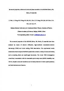
Figure 1.Type of preload
2
Formulation of Static Model
2.1 PRELOAD AND AXIAL PLAY In an application where accurate rotation is needed, the radial play must be removed from the bearing. The radial play is normally removed by using a pair of bearings which are preloaded to remove the play by pressing the races together axially until the balls are in firm contact with the raceways, shown in figure 1.
Once the preload has been applied, the balls wills sit at the ball contact angle. This angle will increase as more preload is applied, and the starting value of this angle (the initial contact angle) will be larger for larger radial play values, shown in figure 2 [8].
Figure 2. Initial contact angles vs. radial play A typical ball bearing geometry and contact angle after applying load is shown in figure 3.
Proceedings of the 5th WSEAS Int. Conf. on Instrumentation, Measurement, Circuits and Systems, Hangzhou, China, April 16-18, 2006 (pp117-122)
(a)
Figure 4. Stiffness of assembly is given by inverse slope of this curve.
2.3 Mathematical formulation The bearings are identical and have a back-to-back configuration. The cage of ball bearings assumed to be constant. Figure 5 shows the geometry of the i th ball of an angular contact ball bearing which is in contact with the inner and outer races. The local Hertzian contact force Fi and deflection δ i relationship between ball i and inner and outer races of angular contact ball bearing may be written as follows [8]:
(b) Figure 3.(a) Geometry of a typical ball bearing, (b) Contact angle after applying load.
Fi = Kδ i
2.2 DISPLACEMENT DUE TO AXIAL PRELOAD
Where K is the total stiffness coefficient per ball. The total deflection δ i of the i th ball-race contact is shown in figure 3b. In this figure the center of curvature of the outer race Oo is assumed to be the
A calculation can be made to determine the displacement vs. preload curve for a given bearing, shown in figure 4 [14].
stiffness = ΔFa Δδ
(1)
32
(2)
fixed origin. It is assumed that the initial preload Fr will cause an axial displacement from Oi to (Oi )1 for the free center of curvature of the inner race. Furthermore, the external radial loading due to the radial process ( Fx and F y ) will move (Oi )1 to a final position (Oi ) 2 . The preload contact angle α p and initial contact deformation δ o due to the elasticity of the bearings for a given preload Fr can be determined by solving the following equations simultaneously using the Newton-Raphson defined as [8]
Proceedings of the 5th WSEAS Int. Conf. on Instrumentation, Measurement, Circuits and Systems, Hangzhou, China, April 16-18, 2006 (pp117-122)
n( Kδ o3 2 ) sin α p = Fr ⎛ cos α 0 ⎞ − 1⎟ δ o = A⎜⎜ ⎟ ⎝ cos α p ⎠
(3)
3
(4)
3.1 Mathematical Formulation 3.1.1 Micro slip Torque
Where A is the initial distance between the centers of curvature of the inner and outer races, α 0 the unloaded contact angle due to interference fitting of bearings ΔC d calculated from the following equation:
⎛
α 0 = cos −1 ⎜1 − ⎝
C d − ΔC d ⎞ ⎟ 2A ⎠
(5)
Formulation of Dynamic Model
The micro slip torque at the outer race in ball bearing given by
Fm ⋅ Ri (9) 2 Where Tm is micro slip torque at the outer race and Fm is the force acting at the ball center which is Tm =
required to cause rolling [4],[5]. For micro slip torque at the inner race is
Tm =
Where
Cd = d − d i − 2D
(6)
The applied axial preload will cause initial displacement Z 0 in the axial direction, as shown in fig. 5.
3.1.2
Fm ⋅ ( Ri + d ) 2
(10)
Hysteresis Torque
The associated bearing torque from the hysteresis per loaded ball along is:
(7)
k Fo α [bi ( Ri + d ) + bo Ri ] (11) 2 d Where i and o refer to inner and outer race respectively, and Ri is the distance of the inner race
The initial contact load per ball F0 due to initial axial
contact from the bearing axis. The related bearing dimension as:
Z0 =
δ 0 sin(α p − α 0 cos α p
preloading Fr can be obtained from
F0 = Kδ
32 0
Th =
Ri = (8)
1 ( PD + D cos α ) 2
(12)
Where PD is the pitch circle diameter, D is the ball diameter and α is the contact angle.
3.1.3
Spin Torque
The torque caused by spin per loaded ball is [5]:
Ts =
3 μFo aE 2 sin α 8
(13)
E2 is the complete elliptic integral of the second kind and may be found from tables or by numerical integration.
4 Fig. 5. deflection of the i th ball-race contact
TEST RIG
A general view of the test rig containing a test bed and a motion control servo amplifiers to drive electro
Proceedings of the 5th WSEAS Int. Conf. on Instrumentation, Measurement, Circuits and Systems, Hangzhou, China, April 16-18, 2006 (pp117-122)
craft dc motor at different switching frequencies is shown in figure 6. The electronic devices are fully protected against over-voltage, over-current, overheating and short - circuits. The set will interface with digital controllers or can be used as stan - alone drives. It requires only a single unregulated DC power supply. Housing assembly shaft is feted on test bed plate. A belt connects motor to the housing assembly shaft. The Velocity Encoder monitors the speed of the shaft at any time. LVDT is installed in mounting blocks, and connects rod between the LVDT core and housing assembly whose motion is being measured.
In the experiments presented in this paper, only axial loading was used. The inner ring was rotated at applicable speed and the frictional torque transmitted across the bearing to the outer ring was sensed by an LVDT. The schematic diagram of the set is shown in figure 8.The transducer output was amplified and fed to a host computer.
comp
DC Drive
system
LVDT
Torque Read out Fig. 8. Schematic diagram of measurement system configuration for ball bearing damage detection All experiments were conducted in control laboratory. The test sampling bearings were degreased and lubricated with applicable amount, and were applied equally and gently in specific area. Some work was done on full ball –complement, caged bearings. Most measurements were made with 6202 series, with the following specifications: Figure 6. Test rig set up
4.1 Test Rig Assembly Before to assemble housing unit to the test bed, with applicable torque watch range, shown in figure 7, we cheeked starting torque to make sure that the set up are with over specifications.
Outer ring diameter Inner ring diameter Ball diameter Contact angle
15 °
Several tests were carried out with different loads with fixed speed or with fixed load with different speeds. Contact angle were determined by the usual method of counting the number of ring revolutions compared with the cage revolutions. The measured frictional torque at speed of 2500 rpm is plotted is figure 9.
5
Fig. 7. Torque watch.
35 mm 12 mm 6 mm
Condition Monitoring
Condition monitoring is an important issue in many fields, including commercial or space applications. Condition monitoring can be defined as a technique or process of monitoring the operating characteristics of a machine so that changes and trends of the monitored signal can be used to predict the need for maintenance before a breakdown or serious deterioration occurs, or to estimate the current condition of the machine.
Proceedings of the 5th WSEAS Int. Conf. on Instrumentation, Measurement, Circuits and Systems, Hangzhou, China, April 16-18, 2006 (pp117-122)
Condition monitoring has become increasingly important. For example, any static overload or severe 4065
TORQUE, gmm
4060
4055
4050
4045
4040
0
50
100
150
200 TIME, ms
250
300
350
400
Figure 9. Frictional sampling torque at 2500 rpm. impact can cause brinelling on the inner ring, outer ring, or balls of the operating machine. An unexpected fault or shutdown can result in a serious accident and financial loss for the company. Companies must find ways to avoid failures, minimize downtime, reduce maintenance costs, and lengthen the lifetime of their equipment. Machines can be utilized in more optimal fashion by using reliable condition monitoring [13].
6 Conclusion Ball bearing is a widely studied subject in condition monitoring [13], [14]. There are several different methods for recognizing failures. The most widely studied methods in ball bearing condition monitoring are based on measurements of vibration, acoustic noise, or temperature, where vibration and stator current based methods seems to be the most popular methods. During the monitoring ball bearing damage in induction motor, the characteristic frequencies of ball bearing damage are often used to monitor certain frequency components in either vibration or stator current signals. In this paper, a tool for condition diagnosis was proposed. The tool aims to be generic and not tied to a specific application; it can automatically find frictional measured torque that discriminate between any signal sets. The most advantage of this tool is the verifying behavior and physical causes of mechanical failures. References: [1] H. Portisky, “Sliding friction of ball bearings of the pivot type.” Journal of applied mechanics, A, pp261-268.
[2] K. L. Johnson “The Effect of Spin upon the Rolling Motion of an Elastic Sphere on a Plane” .Journal of Applied Mechanichs. ASME. 80, 332, 1958. [3] G. S. Reichenbach “The Importance of Spinning Friction in Thrust Carring Ball Bearing” Journal of Basic Engineering, PP295-301,1960. [4] J. Halling “The Micro slip Between a Ball and its Track in Ball Thrust Bearings” Journal of Basic Engineering, PP213-220,1966. [5] J. Halling “Analysis of Spin/Roll Conditions and the Frictional Energy Dissipation in Angular-Contact Thrust Ball Bearings” Proc. I mech. E. 181,PT 1, NO 16,1967. [6] J. Kalker, “The analysis of the motion of the balls in an unlubricated angular contact thrust bearing.” Wear, Vol., 12, No.1. [7] B. Snare “Rolling Resistance in Loaded Ball Bearing” The Ball Bearing Journal, NOS 154 AND 155, 1968. [8] T. Harris “Ball Motion in Thrust- Loaded Angular Contact Bearings With Coulomb Friction” Trans. ASME.JAN.1971. [9] K. L. Johnson “The Effect of Spin upon the Rolling Motion of an Elastic Sphere on a Plane” .Journal of Applied Mechanichs. ASME. 80, 332,1958. [10] S. F. Masri, R. K. Miller,M. I. Traina and T. K. Caughey, “Development of bearing friction models from experimental measurements.” Journal of sound and vibration, Vol. 148, issu 3, 8, 1991, pp. 455-475 [11] X. Hernot, M. Sartor and J. Guillot, “Calculation of the Stiffness Matrix of Angular Contact Ball Bearings by using the analytical approach.” Journal of Mechanical Design, Vol. 122, march 2000. [12] M. O. T. Cole, P. S. Keogh and C.R. Burrows, “The dynamic behavior of a rolling element auxiliary bearing following rotor impact.” Journal of Tribology, Vol., 124, 2002. [13] Y. Hand and Y. H. Song, “condition monitoring techniques for electrical equipment-A literature survey,”IEEE Trans. Power Del., vol. 18, no.1,pp. 413, jan. 2003. [14] B. Yazici and G. Kliman, “An adaptive statistical time-frequency method for detection of broken bars and bearing faults in motors usingstator current,” IEEE Trans. Ind. Appl., vol. 35, no. 2, pp. 442-452, Mar./Apr. 1999.