This environment consists of a set of test images and presentation states for .... and supports both Windows and Unix (Solaris and Linux) systems. ..... performance of these tests is not a prerequisite for standard conformance of the printer ..... cations is available as Open Source Freeware at http://www.offis.de/projekte/dicom/.
DICOM image display consistency: a test environment Jörg Riesmeiera, Marco Eichelberga, Klaus Kleberb, Dietrich H. W. Grönemeyerb, Herman Oosterwijkc, Peter Jenschd a
b
OFFIS e.V., D-26121 Oldenburg, Germany Institute for MicroTherapy, Department of Radiology and MicroTherapy, University Witten/Herdecke, D-44799 Bochum, Germany c OTech Inc., Crossroads, TX 76227, USA d Carl von Ossietzky Universität, D-26111 Oldenburg, Germany ABSTRACT
The DICOM standard has been used successfully to exchange medical images for some time. However, the important aspect of image display consistency has mostly been disregarded in the past, which led to inconsistent implementations. This situation is changing now since DICOM has defined a set of services which guarantee the consistency of grayscale images for both hardcopy and softcopy. We have developed a test environment that helps to evaluate the conformance of an implementation of these new services. This environment consists of a set of test images and presentation states for softcopy displays as well as a number of test cases for hardcopy devices. The purpose of each test as well as the expected output are documented. Images and presentation states can also be visualized by means of a reference implementation, a DICOM presentation state and an image viewer that also allows to visualize print jobs. In our experience the services for image display consistency are implementable and work very well, however, there are some small details that can be subject to different interpretations. The test environment does not cover all possible cases but definitely helps making an implementation more conformant with the DICOM standard. The test suite is made available on the Internet as Open Source. Keywords: DICOM, Display Consistency, Softcopy, Hardcopy, Calibration
1. INTRODUCTION Among the numerous extensions that have been added to the DICOM standard [1] since it’s inception in 1993, the extensions for softcopy and hardcopy image display consistency have received significant attention recently. For example, public demonstrations have been performed at the European Congress of Radiology and the Radiological Society of North America’s annual meeting in 1999 (RSNA), and year 2000 has seen the adoption and implementation of these new DICOM services in the framework of the “Integrating the Healthcare Enterprise” (IHE) initiative. Since the DICOM display consistency extensions have been discussed at length, e. g. in [2], the following paragraphs only provide a short summary. The DICOM Grayscale Standard Display Function (GSDF) [3] describes the non-linear human perceptual response to different levels of luminance in mathematical terms, based on Barten’s model of the human visual system. The GSDF defines a standard curve against which different types of display devices can be calibrated, such that the calibrated image display uses the available contrast of the display device in a perceptually linear way (i. e. the difference between black and 5% gray is perceived equal to the difference between white and 95% gray). A calibration of different types of display devices (e. g. screen/film and grayscale monitor) according to the GSDF cannot yield an identical image display if the physical properties of the display devices in terms of spatial and contrast resolution differ. However, instead of identical, the calibration can yield a consistent image display which means that the appearance of the image to the human observer is as similar as possible given the differing properties of the display devices. The DICOM GSDF model can be applied to a wide range of display devices, including CRT (cathode ray tube) and flat-panel monitors (which are considered as a display system together with the graphics adapter to which they are attached), reflective hardcopy printers (paper) and transmissive hardcopy printers (film).
Grayscale Softcopy Presentation State Storage [4] defines a DICOM Information Object called “Presentation State” that contains an extensive set of parameters defining how a particular image or set of images is to be presented (displayed) to the user: • Grayscale Transformations: The grayscale space of a DICOM image can be modified by a number of linear or nonlinear transformations. The Modality transformation maps the raw image data into a vendor-independent space meaningful for the image modality (e. g. Hounsfield units for CT). The VOI (Value of Interest) transformation selects a window center and width. The Presentation transformation allows to specify a gamma curve or another non-linear correction curve to be applied to the image. • Spatial Transformations: Images can be rotated and flipped (often required for Computed Radiography images or digitized films). In addition, images can be zoomed to a defined “displayed area” (rectangle) or to a specified zoom factor. It is also possible to request the display of an image at its true physical size if this size is known. • Annotations: Images can be annotated with graphical and textual comments displayed as overlays on the image, e. g. in order to highlight regions of interest (ROI) or document measurements on the image. Unlike overlays that are “burned” into the image, annotations encoded in a Presentation State could be displayed and switched off at the user’s discretion. Display shutters allow to mask unwanted parts of the image, e. g. underexposed parts of an X-ray which are displayed very brightly because of collimation and affect the visibility of relevant parts of the image. A Presentation State only contains references to the images it applies to and, therefore, does not duplicate the image data. Presentation State objects are relatively small compared with the actual image itself (typically only few Kbytes) and can be stored and transmitted with a minimal resource increase. Presentation State objects fit well into the established DICOM information model and can be transmitted, stored and retrieved with the existing DICOM storage and query/retrieve services, requiring few changes in existing systems. It is possible to have a single Presentation State for a complete series of images or to have different Presentation States (“views”) for the same image. DICOM Presentation LUT [5] makes the concept of the GSDF available for printing as an extension of DICOM “Basic Grayscale Print Management”. DICOM never defined the precise relationship between image pixel values and luminance or optical density which turned out to be a major problem since different vendors interpreted pixel values differently (e. g. linear to optical density or linear to human perceptual response). Most print vendors addressed this problem by implementing a number of correction curves and configuration options that allow to adapt a printer to the characteristics of the modality from which images are printed. The obvious disadvantage of this approach is that it requires an adaptation of the printer settings for each modality which is to be connected to the printer. While this may be acceptable for installations that use point to point connections with a limited number of modalities and printers, it becomes a significant problem in complex, heterogeneous PACS where printers need to be able to serve requests from a large number of modalities and workstations. The DICOM Presentation LUT supplement provides a solution to this problem by making the parameters which are required to control hardcopy image appearance an explicit part of the communication protocol. The public demonstrations in 1999 have shown that these three new DICOM services are feasible but complex. They are built “on top” of the existing DICOM image display and print services, which are already complex in themselves [6], and add further complexity to them. In addition, an assessment of whether a device correctly implements softcopy or hardcopy display consistency requires appropriate measuring instruments, test patterns, and a good understanding of the DICOM Grayscale Standard Display Function. For the purpose of the implementation of DICOM display consistency in the second year of the IHE initiative [7], RSNA and the Healthcare Information and Management Systems Society (HIMSS) as IHE’s sponsoring bodies have supported the development of a test environment for DICOM display consistency. This test environment consists of a set of test patterns, applications and documents describing how to apply and evaluate the tests. The complete test environment is made available to the public as part of the IHE “Medical Enterprise Simulators and Analyzers” (MESA) test software [8]. The test environment makes use of a reference implementation of a DICOM viewer that is used to visually validate images, softcopy presentation states and print jobs. This reference implementation is based on the “DICOMscope” application [2] which has been initially developed for the public display consistency demonstrations in 1999. The software is platform independent and supports both Windows and Unix (Solaris and Linux) systems.
2. SOFTCOPY TEST ENVIRONMENT The purpose of the softcopy test environment is to assess whether DICOM viewing software correctly implements the DICOM grayscale transformation chain and, if supported by the viewer, the grayscale softcopy presentation state as described above. The test environment consists of a set of monochrome DICOM secondary capture images partly accompanied by appropriate grayscale softcopy presentation states. The parameters of all test files are precisely described in a test
plan document. In addition, for more complex test cases the resulting image is also provided in DICOM secondary capture format. This allows the observer to immediately assess whether an image is displayed correctly. Alternatively the images and presentation states can be displayed using a reference implementation of a DICOM viewer which is also available as part of the test environment. Finally, a spreadsheet is provided that is used to evaluate whether the display system (viewing hardware and software) is correctly calibrated to the GSDF. The test environment altogether contains 134 test cases – 104 of them with presentation states. A set of sample DICOM images and presentation states developed by Dr. David Clunie on behalf of Working Group 11 of the DICOM Committee for the acceptance testing of the “DICOMscope” presentation state reference implementation served as a starting point on which many of the test patterns were modeled.
Figure 1: Softcopy Test Patterns (SMPTE, Gray Ramp, Scrambled Gray Ramp, Complex Presentation State)
Figure 1 shows some of the patterns used for the softcopy test. Most grayscale transformation tests (modality, VOI and presentation) display the well-known test pattern from the Society of Motion Picture and Television Engineers (SMPTE) which contains inter alia 16 boxes with equidistant shades of gray from black to white with a smaller 5% contrast box in the black and white boxes. If the pattern is displayed correctly and the display system is calibrated, the difference between 5% gray and black should be visually equivalent to the difference between 95% gray and white. Another test pattern consists of a gray ramp with 256 shades of gray in the upper half and 16 gray boxes in the lower half. There is also a variant of this pattern where the gray values are scrambled randomly. Most tests for graphic and text annotations use a black image as a background, others also use the SMPTE pattern. Before one starts to use these test patterns it has to be checked whether the display system is calibrated correctly according to the GSDF. This requires a photometer for measuring the luminance of the softcopy display device and the luminance contribution from reflected ambient light.
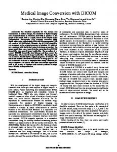
Figure 2: Softcopy GSDF Test Images (4 of 17 different gray values)
A set of 17 DICOM secondary capture images (Figure 2) is provided for this purpose, each of them showing a gray measurement field in the center, surrounded by 50% gray as required by the DICOM standard [3]. For each image the luminance of the gray field is measured and entered into the spreadsheet together with the luminance of the reflected ambient light (if measured separately). In order to get a undistorted result it is very important that the full range of 256 shades of gray is used to display the image. Therefore, an appropriate VOI window is stored in the file and additionally all 256 shades of gray are used in the gray ramp at the lower end of the image to support viewers which are ignoring the stored settings and initially using an automatically computed window. The spreadsheet then calculates the GSDF in the measured range and displays it together with the luminance curve based on the measured values. In addition tabular output is provided that shows the numerical deviation of the measured curve from the GSDF (Figure 3). However, the spreadsheet does not provide an automatic assessment of whether the measured deviation from the GSDF is acceptable or not. This depends on the curve shape
(which should be smooth) and the – application dependent – acceptable percentage of deviation and has to be assessed by a human observer. Softcopy Calibration Form
# DDL Measured* 1 0 0,17 2 16 0,41 3 32 0,84 4 48 1,46 5 64 2,36 6 80 3,48 7 96 4,96 8 112 6,85 9 128 9,39 10 144 12,18 11 160 15,70 12 176 20,02 13 192 25,15 14 208 31,44 15 224 38,72 16 240 47,40 17 255 57,19
100
OFFIS, DICOMscope 3.0 pre 2000-07-05, 17:30 Jörg Riesmeier 0 GSDF 0,17 0,45 0,91 1,57 2,48 3,67 5,20 7,13 9,51 12,44 15,99 20,28 25,43 31,58 38,90 47,59 57,18 Mean: Std. Dev.:
Difference 0,0 0% 0,0 10% 0,1 8% 0,1 7% 0,1 5% 0,2 5% 0,2 5% 0,3 4% 0,1 1% 0,3 2% 0,3 2% 0,3 1% 0,3 1% 0,1 0% 0,2 0% 0,2 0% 0,0 0% 0,2 3% 0,1 3%
Luminance [cd/m²]
Vendor / Device: Date / Time: Performed by: Ambient Light:
10
1 0
64
128
192
256
Measured* GSDF 0 DDL (Device Driving Level)
* including Ambient Light
Figure 3: Softcopy Calibration Form (Output)
The softcopy test environment contains 20 images intended for DICOM viewers that do not support presentation states at all. Most of these images show the SMPTE pattern which is only displayed correctly (i. e. with correct gray values) if the stored modality and VOI transformation parameters are applied exactly as defined in the DICOM standard [4]. One test uses the gray ramp with 9 different VOI settings stored in the image, allowing to assess whether the VOI transformation is implemented correctly by counting the number of visible gray boxes in the lower half. A similar set of test cases is provided for testing the presentation state implementation. In addition, there are tests checking whether the presentation transformation is implemented correctly and whether the grayscale transformation settings in the image are really ignored (as required by the standard) when a presentation state is applied to it. Finally, a combination of all three grayscale transformations is tested. One test case even uses a scrambled image and scrambled LUTs in such a way that the resulting image is “de-scrambled” if and only if all LUTs are applied correctly in accordance with the standard. Besides the multitude of grayscale transformation tests many other aspects of a presentation state are also tested: spatial transformations, displayed areas, display shutters, graphic and textual annotations and overlays. All these test cases are accompanied by a result image showing how the combination of image and presentation state should look like. The final set of test cases combines different aspects to a complex presentation state applying even to individual frames of a multi-frame image or multiple images. It should be noted that DICOM does not standardize all aspects of the visualization of a presentation state. For example, the font type, character size, or line thickness of graphical annotations are implementation dependent. Therefore, the graphical annotations on the result images can slightly deviate from the output created by the image display application under test, however, the information displayed should always be equivalent. All test pattern described above allow to assess whether a DICOM implementation correctly displays images and softcopy presentation states. They do not allow to assess, however, whether an implementation supporting presentation states also correctly creates and stores these DICOM objects. The reference viewer described above allows to display third-party images and presentation states retrieved via DICOM network transmission or loaded from file, enabling a quick visual validation of the image appearance (Figure 4), which should be similar to that of the implementation under test. In addition, the test environment also contains a presentation state validator – an application that reads and checks presentation states for standard conformance. The validator resembles the generic DICOM checker developed by our group some time ago [9] but is dedicated to the testing of grayscale softcopy presentation states only.
Figure 4: Visual Validation of DICOM Image and Presentation State Display
3. HARDCOPY TEST ENVIRONMENT FOR PRINTERS The main purpose of the hardcopy test environment for printers is to assess whether a DICOM printer (Print Management Service Class Provider) correctly implements the optional Presentation LUT that makes display consistency available in the DICOM print protocol and whether the printer is correctly calibrated. In addition, the most usual of the many optional features of the DICOM print service, such as different film layouts, are tested. The test environment consists of a test plan document which describes how to prepare, perform and evaluate the individual tests, a reference implementation of a DICOM print client (Print Management Service Class User) that supports Presentation LUT, and a collection of print jobs (test cases) that can be transmitted to the printer under test with the reference print client. Finally, a spreadsheet is provided that is used to evaluate whether the printer is correctly calibrated to the GSDF. The test environment altogether contains 74 test cases – 37 tests for transmissive media (e. g. film) printers and the same amount for reflective media (e. g. paper) printers. The test cases depend on the type of media because the luminance values for the expected illumination and reflected ambient light on the hardcopy differ significantly for these media types. These parameters, however are required for a correct GSDF calibrated conversion of image data to optical densities, and are transmitted to the printer as part of the Presentation LUT print protocol.
Figure 5: Hardcopy Test Patterns (DSI, 8-Bit Wedge, 12-Bit Wedge, Pixel Aspect Ratio)
Each test case creates a single hardcopy consisting of one or more of the four test patterns shown in Figure 5, printed with different settings for each test case. The DSI test pattern (courtesy of Philips Medical Systems) contains 16 boxes with equidistant shades of gray from black to white. In addition it shows a set of 2% contrast boxes. The 8-Bit Wedge pattern contains a transition from black to white in 45 degree angled lines. This pattern only contains 256 different shades of gray. The 12-Bit Wedge pattern contains four stripes with a transition from black to white in 45 degree angled lines. This pattern contains 4096 shades of gray. The Pixel Aspect Ratio pattern shows a transition from black to white. The source image contains a pixel aspect ratio of 4:1 (512 by 128 pixels). Correctly printed, the image has a square shape. The first set of tests examines whether the printer correctly creates GSDF calibrated hardcopies. This requires a densitometer for measuring the optical density of the printed film (transmissive media) or paper (reflective media). Each of the test cases sends a single image (the DSI pattern shown in Figure 5), a Presentation LUT and well-defined lighting conditions to the printer. Different types of Presentation LUT (shape, look-up table with 256 or 4096 entries) and lighting conditions (usual vs. rather unusual) are used. For each hardcopy, the optical densities of the 16 equidistant gray boxes in the pattern are measured and entered into the spreadsheet together with the luminance values that were used to create the hardcopy. The spreadsheet then calculates the density curve mandated by the DICOM GSDF and displays it together with the measured curve from the hardcopy (Figure 6). For the assessment of the hardcopy calibration the same applies as mentioned before for the softcopy test environment.
Optical Density [OD]
3
2
1
Measured GSDF 0 1
2
3
4
5
6
7
8
9
10
11
12
13
14
15
16
Measured Gray Box
Figure 6: Hardcopy Calibration Spreadsheet Output
The DICOM print protocol contains a multitude of optional parameters and values that may or may not be supported by a particular printer or print client. Since only a small number of these options is negotiated dynamically during connection setup between a DICOM print client and a printer, the print client requires a-priori knowledge about the printer in order to be able to use all available features. Such information is typically available in the DICOM conformance statement of a printer. The so-called Printer Configuration Retrieval SOP Class has been added to the DICOM standard as another optional extension of the print protocol in order to allow a print client to request more detailed information from the printer than available through the negotiation mechanism. Unfortunately, this option is not yet widely supported. The third set of test cases examines how the printer under test reacts on different optional elements of the DICOM print protocol. Successful performance of these tests is not a prerequisite for standard conformance of the printer, but significantly increases the probability that the printer will interoperate with different kinds of print clients. The test cases examine whether the Referenced Presentation LUT Sequence is accepted by the printer on session or film box level (this changed between the 1999 and the 2000 edition of the DICOM standard), whether the printer supports landscape orientation, images with non-square pixels (pixel aspect ratio), explicit transmission of the minimum and maximum density for the hardcopy, inverse polarity, collation (printing of multiple sheets of hardcopy with a single print job) and explicit transmission of the requested image size on the hardcopy. Image transmission with 8 vs. 12 bits/pixel as well as the two different DICOM color models for monochrome images (zero is white vs. zero is black) are exercised.
The fourth set of tests checks the completeness of the Presentation LUT implementation in the printer by using some of the more unusual possibilities of this DICOM service. Look-up tables with unusual bit-depths (11 or 13 bits/entry), data type (“OW” instead of “US”) or content (non-monotonous mapping) are sent to the printer as well as look-up tables with a number of entries that does not match with the image pixel data (e. g. a look-up table with 4096 entries but image pixel data with only 8 bits/pixel). Finally, the optional “LIN OD” Presentation LUT shape, in which pixel data is transmitted in optical densities instead of the conventional P-value space (grayscale space proportional to human visual perception) as defined by the DICOM Grayscale Standard Display Function, is tried out. The final set of tests examines whether the printer supports the most common page layouts (image display formats). Again the layouts supported by one particular DICOM printer are completely application defined (there is no required “least common denominator”), but one would expect that at least the layouts 2×2, 3×5, 4×5 and 4×6 would be supported by most printers. As with the second set of tests, successful performance of these tests increases the probability that the printer will interoperate with different kinds of print clients.
4. HARDCOPY TEST ENVIRONMENT FOR PRINT CLIENTS With DICOM print, the activity that finally leads to the creation of one or more hardcopies is always initiated by the print client as the result of some “real world activity”, for example by the user selecting the “print” function on some device’s user interface. In addition, a print client has many “degrees of freedom” in terms of support for optional attributes of the DICOM print protocol. This support might be configurable by some implementation specific means, but it cannot be influenced over the DICOM interface. For this reason, a test environment for print clients cannot consist of a static collection of test cases that force the print client to react on some input. Instead, we have implemented a highly configurable reference DICOM print server that allows to analyze the DICOM communication between print client and printer as well as the visual appearance of the hardcopies requested by the print client. The configurable options for the reference print server include • • • •
•
the implementation of Presentation LUT: supported or unsupported, match between pixel data and number of look-up table entries required or not, compliance with 1999 or 2000 edition of the DICOM standard, the supported layout formats, whether or not image transmission with 12 bits/pixel is possible, the supported optional attributes and attribute values of the print protocol, including border density, empty image density, film destination, film size ID, magnification type, smoothing type, medium type, requested resolution ID, maximum and minimum density, trim, requested image size and requested decimate/crop behavior, network protocol options such as the negotiated encoding schemes (transfer syntaxes) and whether or not the SOP Class UID is included in N-CREATE response messages.
These options, which are read from a configuration file during application startup, allow the reference print server to mimic the behavior of a multitude of DICOM printers and to test how well a print client co-operates with a printer that exhibits a specific behavior on the DICOM protocol level. The test environment comes with two proposed printer configurations: The first one implements most of the optional features of the DICOM print protocol and should easily communicate with most print clients. The second configuration restricts the print server to the bare minimum of services required by the IHE Technical Framework [7], i. e. implements some kind of smallest common denominator one can expect from most real-world printers. This configuration makes it of course much more difficult for a print client to successfully create a hardcopy – if the print client incorrectly assumes that any of the optional elements of the DICOM print protocol are available, the reference print server is likely to refuse this setting, i. e. send back an error code to the print client. The print server creates detailed logs of all DICOM communication with the print client that can be used for a syntactical validation of the DICOM print communication. Figure 7 shows an example for the DICOM message log. It contains an N-SET request for a Basic Grayscale Image Box (i. e. image transmission from the print client to the printer). Evaluation of the log requires a basic understanding of the DICOM Message Service Element (DIMSE) and the definition of the DICOM Print Management Service Class. This knowledge provided, the log allows to check for example whether a Presentation LUT has been created and correctly referenced (activated) by the print client, i. e. whether the print client has correctly set up the parameters for hardcopy display consistency. For most protocol errors detected by the print server, additional diagnostic information is stored in the log file.
===================== INCOMING DIMSE MESSAGE ==================== Message Type : N-SET RQ Message ID : 5 Requested SOP Class UID : BasicGrayscaleImageBoxSOPClass Requested SOP Instance UID : 1.2.276.0.7230010.3.4.2139363186.2206.960455839.7 Data Set : present # Dicom-Data-Set # Used TransferSyntax: BigEndianExplicit (2020,0010) US 1 # 2, 1 ImageBoxPosition (2020,0110) SQ (Sequence with explicit Length #=1) #2097262, 1 BasicGrayscaleImageSequence (fffe,e000) na (Item with explicit Length #=9) #2097254, 1 Item (0028,0002) US 1 # 2, 1 SamplesPerPixel (0028,0004) CS [MONOCHROME2] # 12, 1 PhotometricInterpretation (0028,0010) US 1024 # 2, 1 Rows (0028,0011) US 1024 # 2, 1 Columns (0028,0100) US 16 # 2, 1 BitsAllocated (0028,0101) US 12 # 2, 1 BitsStored (0028,0102) US 11 # 2, 1 HighBit (0028,0103) US 0 # 2, 1 PixelRepresentation (7fe0,0010) OW 0160\0160\0160\0160\0177\0177\0177\0177\017d\017d... #2097152, 1 PixelData (fffe,e00d) na (ItemDelimitationItem for re-encoding) # 0, 1 ItemDelimitationItem (fffe,e0dd) na (SequenceDelimitationItem for re-enc.) # 0, 1 SequenceDelimitationItem ======================= END DIMSE MESSAGE =======================
Figure 7: Log of DICOM Print Communication
The reference print server is not connected to any real printer hardware, instead it saves the received print jobs in a DICOM database. Each Film Box (the DICOM term for a single sheet of hardcopy) is stored as a DICOM Stored Print object and each image is stored as a DICOM Hardcopy Grayscale Image object. A Print Preview application based on the DICOMscope software presented in [2] allows to load such a “virtual hardcopy” and displays it on-screen as a softcopy rendering (Figure 8).
Figure 8: Visual Validation of DICOM Print Communication
If the application is correctly calibrated, the print preview is even displayed with GSDF calibration. Certain optional attributes such as the magnification and smoothing algorithm are ignored in the print preview. However, the most important parameters for a visual validation of the appearance of the print job, e. g. image data, polarity, layout, orientation and all Presentation LUTs (including the optional “LIN OD” Presentation LUT shape described above) are correctly displayed. This allows to quickly check whether the hardcopy looks like what the user would expect from the print settings selected in the print client under test.
5. DISCUSSION The test environment introduced in this paper is intended to facilitate the conformance testing of implementations of the DICOM image display consistency services. Hence the general remarks in ISO 9646-1 [10] about the purpose and limitations of conformance testing also apply for our approach: The purpose of conformance testing is to increase the probability that different […] implementations are able to interwork. However it should be borne in mind that the complexity of most protocols makes exhaustive testing impractical on both technical and economic grounds. Also, testing cannot guarantee conformance to a specification since it detects errors rather than their absence. Thus conformance to a test suite alone cannot guarantee interworking. What it does do is give confidence that an implementation has the required capabilities and that its behaviour conforms consistently in representative instances of communication. In addition to the testing procedures itself, the test environment also comprises a reference implementation of the DICOM image display consistency services. The idea of providing publicly available reference implementations against which other implementations of the standard can be tested as a means of improving interoperability has been promoted in the DICOM area since the inception of the standard. “Central Test Nodes” such as the DICOM implementation from the Mallinckrodt Institute of Radiology or the “European CTN” [11] have been available as long as the DICOM standard itself and have arguably contributed to the quick adoption of the standard both by industry and the healthcare professionals. It is the authors’ hope that the display consistency reference implementation will contribute to the success of the DICOM image display consistency services in a similar manner. It is important to understand, though, that a reference implementation can never be a replacement for the standard. If an implementation under test exhibits a behavior that is inconsistent with the reference implementation, the reason can either be an ambiguity in the standard allowing for differing interpretations, an error in the implementation under test, or an error in the reference implementation. However, a comparison with the reference implementation points out potential problems requiring further analysis, and this has shown to be useful in the past. When designing a set of tests, one of the most important issues is test coverage. Since the problem of “combinatorial explosion” makes it impossible to cover all valid combinations of data elements and data element values, our test cases are restricted to two different sets: •
Typical test cases cover the cases that can be expected in “real life”, i. e. the most conventional DICOM image models and the most usual print options (layout formats etc.) Any application should be able to correctly handle at least these typical cases.
•
Atypical test cases attempt to provoke application failure by using options that are legal but unusual and unlikely to occur in “real life”. A good example is the “scrambled look-up table” test case used in the softcopy test environment: It contains a set of non-monotonous look-up tables that “de-scramble” the image data if applied in the correct order. While being perfectly legal DICOM, it’s properties are unusual and cause incorrect display if an application assumes properties that are usual but not guaranteed by the standard (such as monotony of the look-up tables). In this particular case, the image display will be incorrect if an image viewer displays the image using magnification and interpolation, but performs magnification before applying the look-up tables.
Obviously, the choice of “typical” and “atypical” test cases is a reflection of the authors’ opinion on which cases are to be expected in “real life” and which ones are likely to be unsupported or implemented incorrectly. During the development and use of the test environment it turned out that the appropriate choice is not always obvious – for example, the authors had not expected to encounter a “real life” DICOM printer that does not support printing in landscape orientation. The gaps that became obvious during the development period were filled, but a wider use of the test environment in the future will most probably create the need for additional test cases not present yet. Finally it should be noted that the test environment only contains correct (standard compliant) test cases. It can be used to test an application for standard conformance, but not for robustness, i. e. the ability to gracefully handle incorrect data. The great complexity of the DICOM standard would allow for a number of “erroneous” test cases by far exceeding the number of correct cases. Such errors could include semantic errors (invalid or inconsistent attribute values, missing attributes) and syntactic errors (incorrect encoding) in the DICOM objects and messages as well as protocol errors in the DICOM network protocol. We have considered this field as “outside the scope of” the current test set, yet it would be a very useful undertaking since DICOM software has to be prepared to encounter incorrect data in “real life”.
6. CONCLUSION Based on the reactions from the “user community” we can conclude that the test environment introduced in this paper is indeed a useful tool for testing the standard conformance of devices implementing the DICOM image display consistency services for softcopy or hardcopy. Of course the test environment cannot overcome limitations of the standard itself: The number of optional data elements and attribute values in complex DICOM objects (e. g. grayscale softcopy presentation state) and network services (e. g. print management) is very large, and the SOP class based granularity with which options are negotiated between applications is extremely low. This makes it unlikely that an application can ever be tested even for all combinations of values it should be able to handle. Some of the DICOM objects and services developed more recently, such as Printer Configuration Retrieval or the revised secondary capture object [12] try to relieve this problem by making more features negotiable or defining DICOM SOP classes on a finer level of granularity. The “definite solution” for this problem, however, still remains to be invented. The test environment consisting of test plan documents, test cases and applications is available as Open Source Freeware at http://www.offis.de/projekte/dicom/.
REFERENCES 1.
NEMA Standards Publication PS 3.x, Digital Imaging and Communications in Medicine (DICOM), National Electrical Manufacturers Association, 2101 L Street, N. W., Washington, D. C. 20037, 1992-2000.
2.
Eichelberg M, Riesmeier R, Kleber K, Holstein J, Oosterwijk H, Jensch P: Consistency of Softcopy and Hardcopy: Preliminary Experiences with the new DICOM Extensions for Image Display, in: PACS Design and Evaluation: Enineering and Clinical Issues, Blaine GJ, Siegel EL, Editors, Proceedings of SPIE Vol. 3980, pp. 57-67 (2000)
3.
NEMA Standards Publication PS 3.14, Digital Imaging and Communications in Medicine (DICOM), Part 14: Grayscale Standard Display Function, National Electrical Manufacturers Association, 2101 L Street, N. W., Washington, D. C. 20037, 1998-99.
4.
DICOM Standards Committee, Working Group 11 Display: Digital Imaging and Communications in Medicine (DICOM), Supplement 33: Grayscale Softcopy Presentation State Storage, Final Text, September 1999.
5.
DICOM Standards Committee, Working Group 6 Printer Ad Hoc: Digital Imaging and Communications in Medicine (DICOM), Supplement 22: Presentation Look Up Table (LUT), Final Text, January 1998.
6.
Riesmeier J, Eichelberg M, Jensch P: An approach to DICOM image display handling the full flexibility of the standard's specification, in: Proceedings SPIE '99 Vol. 3658, pp. 363-369 (1999)
7.
HIMSS and RSNA – Integrating the Healthcare Enterprise: IHE Technical Framework Year 2, Revision 4.0, March 2000
8.
Integrating the Healthcare Enterprise, http://www.rsna.org/IHE/
9.
Hewett AJ, Grevermeyer H, Barth A, Eichelberg M, Jensch P: Conformance Testing of DICOM Image Objects, in: Steven C. Horii, G. James Blaine: Medical Imaging 1997: PACS Design and Evaluation: Engineering and Clinical Issues, Proceedings SPIE Vol. 3035, pp.480-487 (1997)
10. International Organization for Standardization: Information technology -- Open Systems Interconnection -- Conformance testing methodology and framework -- Part 1: General concepts, ISO 9646-1 (1994) 11. Jensch P, Hewett AJ, Cordonnier E, Mattheus R: DICOM 3.0 - The CEN Trial Implementation, in: SPIE Medical Imaging, PACS Design and Evaluation, Newport Beach, Calif., Vol. 2165, Feb., pp.368-377 (1994) 12. DICOM Standards Committee: Digital Imaging and Communications in Medicine (DICOM), Supplement 57: Revised Secondary Capture Objects, Public Comment, September 2000.