for the Efficient Simulation of 2D EC. Structures. Davy Pissoort'", Dries Vande Ginste', Frank Olyslager' and Eric Michielssen'. ' Ucpanmcnl uf lnfnmrlton ...
Different Preconditioning Techniques for the Efficient Simulation of 2D EC Structures Davy Pissoort'", Dries Vande Ginste', Frank Olyslager' and Eric Michielssen'.
' Ucpanmcnl uf lnfnmrltonTechnolug) (INTtC). Chcnt Univcrsily. St..Rcrcrsnicuwstraar 41, 8-9000Cent. Bclgrvm
' Center for CompurrlronalElccuomagnclics. Unircrrily of lllinoir at Urbana-Champaign,Urbana, IL 61801. USA E.mul davy prrsoort@in~ecUgcn8.bc
Abslroct-When analyzing wave propagation in electromagnetic crystals using multilevel fast multipole accelerated Integral equation methods. the total number of iterations required for the solver to converge often is large. This paper discusses the effectiveness of various techniques for preconditioning the linear systems of equations arising in the analysis of ECs. In addition, it introduces a new physics-based preconditioner that effectively deflates the original system by accounting for all quasi-resonant mode.; dircctly (as opporcd lo iteratively).
I. INTRODUCTION Recently, electromagnetic crystals (ECs) have been studied widely as their careful design enables the manipulation of electromagnetic waves at spatial scales smaller than achievable by classical fiber structures [I]. The ECs studied in this paper consist of Ncvl parallel homogeneous dielectric or perfectly conducting (PEC) cylinders that snap to a periodic lattice and that reside in a homogeneous background medium. Because of the lattice periodicity, such structures exhibit electromagnetic bandgaps, viz frequency bands in which no electromagnetic fields are allowed to propagate in given directions. By removing or adding cylinders to an otherwise perfectly periodic constellation, the resulting structure may be able to support localized electromagnetic modes. This phenomenon can be exploited to create low loss waveguides, multiplexers, splitters, etc. As these sttuctures are often electromagnetically large, usage of computationally efficient methods is imperative to their simulation. In [2], we presented a rigorous semi-analytical technique for the simulation of 2D ECs. However, this method requires the solution of a dense linear system of equations whose dimension scales linearly with the number of cylinders. Carrying out this operation using an iterative solver reduces the computational complexity to O ( P N Z )or even O ( P N l o g ( N ) )if one combines the method described in [21 with the multilevel fast multipole algorithm (MLFMA) [3]. Here, P is the number of iterations required for the iterative solver to reduce residual errors below a desired threshold. Numerical experiments have shown that, due to the existence of near-resonant modes in many realistic ECs, their analysis often requires an exorbitant number of iterations. As a consequence, preconditioning is a must. In this paper, various preconditioners are compared on their relative merits and performance, and a new physics-based preconditioner that deflates the original system and directly as opposed to iteratively accounts for all quasi-resonant modes is introduced. 11. BASK CONFIGURATIONS AND FORMULATION
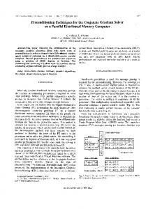
The effectiveness of the different preconditioning techniques will be tested on two basic configurations, namely a block of cylinders (Fig. 1) and a straight EC waveguide (Fig. 2). The radius r and the relative dielectric constant er of the dielectric cylinders are 0.18a and 11.56, respectively. Here, a is the lattice constant. The background medium is air and the frequency equals f = 0.36;. In 121, local cylindrical coordinate systems ( p j , $ j ) centered at every cylinder j = 1 , . . . , N,, were defined. Furthermore, the unknown surface currents were expanded in terms of a truncated Fourier series
0-7803-8302-8/04/$20.00 02004 IEEE 2131
Current modelled by a term in the above expansion generates a cylindrical wave. The boundary conditions at the surface of every cylinder were enforced by using a Fourier decomposition in combination with an appropriate boundary impedance to obtain a dense linear system of equations Ne..! K
Z 2 i I i =e:, j=1
i = 1,.. . ,N,,I andp = - K , .
. . ,K ,
(2)
m=-K
with
Three unknowns per cylinder ( K = 1)are usually sufficient for the solution to converge. 111. PRECONDITIONING TECHNIQUES
The following four preconditioning techniques will be compared on their performance and overall merits: Diagonal preconditioner: only the diagonal elements of the interaction matrix are retained and used to construct an approximate inverse of the system matrix. Block-diagonal preconditioner: the EC-structure is divided into groups and the inverse of the small interaction matrix of every group is calculated by a direct method. Moving-block-diagonal preconditioner: similarly to the block-diagonal preconditioner, the EC structure is divided into groups. However, now.for each block, the submatrix describing its interactions with itself and with its neighbors is inverted, and an approximate inverse is constructed by retaining only those rows of this inverse that correspond with the unknowns in the center block. System deflation: first the smallest singular values and the corresponding eigenvectors are determined with e.g. an inverse power method [4]. These singular values are then artificially cranked up, so that they are on the order of "1". This creates a new interaction matrix, for which the iterative solver converges much faster. This technique will be described in more detail in the next section. The groups that are used to form the block-diagonal and the moving-block-diagonal preconditioners are shown in Fig 1 and Fig. 2 and consist of Nb rows. Remark that the computational effort to calculate the moving-block-preconditioner with Nb = M is almost the same as that for the blockpreconditioner with Na = 3 M . As an iterative solver, the QMR-routine of Matlab was used.
. .
.
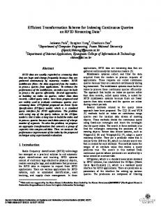
IV. DISCUSSION Figures 3 and 4 show the residual error versus the iteration count for a block of cylinders and an EC waveguide (with both 2160 unknowns) for the first three types of preconditioners described above and for different values of Nb. When using only a diagonal preconditioner for the EC waveguide, the residual error quasi-stagnates for many iterations. The block-diagonal and the movingblock-diagonal preconditioner alleviate this phenomenon drastically. For both configurations, the moving-block-diagonal preconditioner seems to be the best choice. For this preconditioner there is no difference between unknowns sitting at the edge of the blocks and those in the center. In order to try to find an explanation why the required number of iterations is much higher for an EC waveguide than for a simple block of cylinders without a waveguide channel, a singular value decomposition (SVD) of the interaction matrix was performed and this for increasing lengths L of the structures. Fig 5 and Fig. 6 show the 50 smallest singular values for respectively the block of cylinders and the EC waveguide. There is clearly a crack in the singular values for the EC waveguide. The behavior before this crack is the same as for the block of cylinders, while the singular values after the crack decrease rapidly. Also the number of these small 'special' singular values increases as L increases. As a consequence, the system deflation technique that was briefly introduced in the previous section seems an interesting alternative way to reduce the required number of iterations for realistic EC structures. Suppose that the original system of linear equations is given by
zT = u w H =i E ,
2132
(4)
with U and V unitary matrices containing the right and left eigenvectors and S a diagonal matrix containing the singular values. By crankinaup the k smallest singular values, the interaction matrix 2 is replaced by a new interaction matrix 2 = 2 U A S V H with , A S a (n x k)-matxix. Hence, the calculation of this new interaction matrix can be done efficiently as we only need to calculate the k smallest singular values and their corresponding eigenvectors. Of course, the solution achieved by solving this new system is incorrect. We can however easily obtain the correct solution by adjusting the excitation vector E. The solution of (4) is given by = VS-'U"E. so
+
i f= zi+ U A S V " ~= E + U A S S - ~ U ~ E
(5)
In Fig. 7 the residual error is plotted as a function of the number of iterations for the deflation technique and compared with that when no preconditioner is used for an EC waveguide with 1152 unknowns. The plateau in the residual error - iteration count graph is now eliminated. As a more complex example, we consider the EC coupler structure shown in Fig. 8. The total number of unknowns for this structure is 1485. The 50 smallest singular values are shown in Fig. 9 and again there is an obvious crack. Fig. 10 shows the residual error in function of the number of iterations for increasing number of cranked up singular values. Cranking up more than 20 singular values doesn't improve the behavior of the residual error any longer. Of course, this deflation technique can be combined with the other preconditioning techniques. V. ACKNOWLEDGEMENT
D.Pissooft is a Research Assistant of the Fund for Scientific Research - Flanders (Belgium)(F.W.O. - Vlaanderen). REFERENCES [ I ] J. D.Jomopoulos, R. D.Meade. and I. N.Winn, Pholonic CryslaLr. Molding the Flow of Light. N.J.: Princeton Univ. Press, 1995. [2] D.Pissmn, D.De ZuIter, and E Olyslager, "'Efficientsemi-analyticalanalysis of two-dimensional phatonic crystals:' in IEEEAP-Slnl. Sy"., vol. 3, Columbus, USA, June 2003. pp. 994-997. [31 W.C. Chew. 1. M.Iin, E. Michielssen, and 1. Song. Fast and Eficirnl Algorifhms in Computnfionnl Eledmmgnetics. Boston: Artech House, 2001. 141 . . G. H. Golub and C. F.Van Loan. Mal* Comoiuutions. Baltimore, Maryland The Johns Hopkins Univcnity Press, 1983.
Id,
.
4
4a
L
.I
Fig. 1. Blackof cylinders
Rg. 2. EC waveguide
.
,
na do
.
i i
.
mo
CA
Fig. 3. Residual emor for P block of cylinders
Fig. 4. Residual error for an EC waveguide
2133
-
1 0,s
-
0.3-
0.3.
0.2
020.1 -
0.1.
0'
L-30101.
Ib
2b
30
;O
io
Fig. 5. Smallest singulru values for a block of cylinders
Fig. 6. Smallest singular values for an EC waveguide
Fig. 1. Deflation technique for an EC waveguide
Fig. 8. EC couplcr
i 0.7
T
]
Fig. 9. Smallest singular values of an EC coupler
2134